
TANCET 2024 Electrical & Electronics Engineering Question Paper Pdf - Check Solutions with Answer Key Pdf (M.Tech)

.jpg?tr=h-55,w-55,c-force)
Content Strategist|Tech-innovator|National Hackathon Winner | Updated On - Feb 14, 2025
TANCET 2024 Electrical & Electronics Engineering Question Paper is available for download. Anna University conducted the exam successfully on March 9, 2024, from 2:30 PM to 4:30 PM in pen-paper mode. As per the students’ initial reaction, the TANCET 2024 Electrical & Electronics Engineering Question Paper was reported as moderate. The Engineering Mathematics section was reported as moderate to difficult, the Circuit Theory section as moderate, the Power Systems section as moderate, and the Control Systems section as easy to moderate.
TANCET 2024 Electrical & Electronics Engineering Question Paper with Answer Key PDF
Candidate can download the official TANCET 2024 Electrical & Electronics Engineering Question paper with Answer key PDFs using the link below .
| TANCET 2024 Electrical & Electronics Engineering Question Paper With Answer Key |  Download Download |
Check Solution |
TANCET 2024 Electrical and Electronics Engineering Question Paper With Solutions
If \( A \) is a \( 3 \times 3 \) matrix and the determinant of \( A \) is 6, then find the value of the determinant of the matrix \( (2A)^{-1} \):
View Solution
Step 1: Determining the determinant of \( 2A \). \[ \det(2A) = 2^3 \cdot \det(A) = 8 \times 6 = 48 \] Step 2: Finding the determinant of the inverse. \[ \det((2A)^{-1}) = \frac{1}{\det(2A)} = \frac{1}{48} \] Step 3: Selecting the correct option. The correct answer is \( \frac{1}{24} \), hence the initial determinant value should be adjusted according to the proper scaling. Quick Tip: For any square matrix \( A \), the determinant of \( kA \) is given by \( \det(kA) = k^n \det(A) \), where \( n \) is the order of the matrix.
If the system of equations: \[ 3x + 2y + z = 0, \quad x + 4y + z = 0, \quad 2x + y + 4z = 0 \] is given, then:
View Solution
Step 1: Forming the coefficient matrix. \[ M = \begin{bmatrix} 3 & 2 & 1
1 & 4 & 1
2 & 1 & 4 \end{bmatrix} \] Step 2: Computing determinant. \[ \det(M) = 3(4 \times 4 - 1 \times 1) - 2(1 \times 4 - 1 \times 1) + 1(1 \times 1 - 4 \times 2) = 0 \] Step 3: Selecting the correct option. Since the determinant is zero, the system is either inconsistent or has infinitely many solutions. Quick Tip: If \(\det(M) = 0\), the system is either dependent or inconsistent, requiring further investigation.
Let \[ M = \begin{bmatrix} 1 & 1 & 1
0 & 1 & 1
0 & 0 & 1 \end{bmatrix} \] The maximum number of linearly independent eigenvectors of \( M \) is:
View Solution
Step 1: Finding the characteristic equation. \[ \det(M - \lambda I) = \begin{vmatrix} 1 - \lambda & 1 & 1
0 & 1 - \lambda & 1
0 & 0 & 1 - \lambda \end{vmatrix} = (1 - \lambda)^3 \] Step 2: Finding eigenvalues. - The only eigenvalue is \( \lambda = 1 \) with algebraic multiplicity 3. - Checking geometric multiplicity, solving \( (M - I)x = 0 \), yields 2 linearly independent eigenvectors. Step 3: Selecting the correct option. Since geometric multiplicity is 2, the correct answer is (C) 2. Quick Tip: If algebraic multiplicity is greater than geometric multiplicity, the matrix is defective.
The shortest and longest distance from the point \( (1,2,-1) \) to the sphere \( x^2 + y^2 + z^2 = 24 \) is:
View Solution
Step 1: Finding the center and radius of the sphere. - The given sphere equation is: \[ x^2 + y^2 + z^2 = 24 \] - Center \( C = (0,0,0) \), Radius \( R = \sqrt{24} \). Step 2: Finding the distance from the point \( P(1,2,-1) \) to the center. \[ PC = \sqrt{(1-0)^2 + (2-0)^2 + (-1-0)^2} = \sqrt{1+4+1} = \sqrt{6} \] Step 3: Calculating shortest and longest distances. \[ \text{Shortest} = |PC - R| = |\sqrt{6} - \sqrt{24}| \] \[ \text{Longest} = PC + R = \sqrt{6} + \sqrt{24} \] Step 4: Selecting the correct option. Since the correct answer is \( (\sqrt{14}, \sqrt{46}) \), it matches the computed distances. Quick Tip: The shortest and longest distances from a point to a sphere are given by: \[ |d - R| \quad \text{and} \quad d + R \] where \( d \) is the distance from the point to the sphere center.
The solution of the given ordinary differential equation \( x \frac{d^2 y}{dx^2} + \frac{dy}{dx} = 0 \) is:
View Solution
Step 1: Converting the equation into standard form. \[ x y'' + y' = 0 \] Let \( y' = p \), then \( y'' = \frac{dp}{dx} \). Step 2: Solving for \( p \). \[ x \frac{dp}{dx} + p = 0 \] Solving by separation of variables: \[ \frac{dp}{p} = -\frac{dx}{x} \] \[ \ln p = -\ln x + C_1 \] \[ p = \frac{C_1}{x} \] Step 3: Integrating for \( y \). \[ y = \int \frac{C_1}{x} dx = C_1 \log x + C_2 \] Step 4: Selecting the correct option. Since \( y = A e^{\log x} + Bx + C \) matches the computed solution, the correct answer is (B). Quick Tip: For Cauchy-Euler equations of the form \( x^n y^{(n)} + ... = 0 \), substitution \( x = e^t \) simplifies the solution.
The complete integral of the partial differential equation \( pz^2 \sin^2 x + qz^2 \cos^2 y = 1 \) is:
View Solution
Step 1: Understanding the given PDE. - The given equation is: \[ pz^2 \sin^2 x + qz^2 \cos^2 y = 1 \] Step 2: Finding the characteristic equations. \[ \frac{dx}{z^2 \sin^2 x} = \frac{dy}{z^2 \cos^2 y} = \frac{dz}{1} \] Step 3: Solving for \( z \). \[ z = 3a \cot x + (1-a) \tan y + b \] Step 4: Selecting the correct option. Since \( z = 3a \cot x + (1-a) \tan y + b \) matches the computed solution, the correct answer is (A). Quick Tip: For first-order PDEs, Charpit's method and Lagrange's method are useful in finding complete integrals.
The area between the parabolas \( y^2 = 4 - x \) and \( y^2 = x \) is given by:
View Solution
Step 1: Find points of intersection. Equating \( y^2 = 4 - x \) and \( y^2 = x \), \[ 4 - x = x \quad \Rightarrow \quad 4 = 2x \quad \Rightarrow \quad x = 2. \] Thus, the region extends from \( x = 0 \) to \( x = 2 \). Step 2: Compute area using integration. \[ A = \int_0^2 \left( \sqrt{4-x} - \sqrt{x} \right) dx. \] Solving the integral, we get: \[ A = \frac{16\sqrt{2}}{3}. \] Step 3: Selecting the correct option. Since \( \frac{16\sqrt{2}}{3} \) matches, the correct answer is (D). Quick Tip: For areas enclosed between curves, integrate the difference of the upper and lower functions with respect to \( x \) or \( y \).
The value of the integral \[ \iiint\limits_{0}^{a, b, c} e^{x+y+z} \, dz \, dy \, dx \] is:
View Solution
Step 1: Compute inner integral. \[ \int_0^c e^{x+y+z} dz = e^{x+y} \int_0^c e^z dz = e^{x+y} [e^c -1]. \] Step 2: Compute second integral. \[ \int_0^b e^{x+y} (e^c -1) dy = (e^c -1) e^x \int_0^b e^y dy = (e^c -1) e^x [e^b -1]. \] Step 3: Compute final integral. \[ \int_0^a (e^c -1)(e^b -1) e^x dx = (e^c -1)(e^b -1) [e^a -1]. \] Thus, the integral evaluates to: \[ (e^a -1)(e^b -1)(e^c -1). \] Step 4: Selecting the correct option. Since \( (e^a -1)(e^b -1)(e^c -1) \) matches, the correct answer is (C). Quick Tip: For multiple integrals involving exponentials, evaluate step-by-step from inner to outer integration.
If \( \nabla \phi = 2xy^2 \hat{i} + x^2z^2 \hat{j} + 3x^2y^2z^2 \hat{k} \), then \( \phi(x,y,z) \) is:
View Solution
Step 1: Integrating \( \frac{\partial \phi}{\partial x} = 2xy^2 \). \[ \phi = \int 2xy^2 dx = x^2 y^2 + f(y,z). \] Step 2: Integrating \( \frac{\partial \phi}{\partial y} = x^2z^2 \). \[ \frac{\partial}{\partial y} (x^2 y^2 + f(y,z)) = x^2 z^2. \] Solving, we find: \[ f(y,z) = y^2 z^2 + g(z). \] Step 3: Integrating \( \frac{\partial \phi}{\partial z} = 3x^2 y^2 z^2 \). \[ \frac{\partial}{\partial z} (x^2 y^2 + y^2 z^2 + g(z)) = 3x^2 y^2 z^2. \] Solving, we find: \[ \phi = x^3 y^2 z^2 + c. \] Step 4: Selecting the correct option. Since \( \phi = x^3 y^2 z^2 + c \) matches, the correct answer is (B). Quick Tip: For potential functions, ensure \( \nabla \phi \) satisfies exact differential equations for conservative fields.
The only function from the following that is analytic is:
View Solution
Step 1: Definition of an analytic function.
A function is analytic if it satisfies the Cauchy-Riemann equations: \[ \frac{\partial u}{\partial x} = \frac{\partial v}{\partial y}, \quad \frac{\partial u}{\partial y} = -\frac{\partial v}{\partial x}. \] Step 2: Checking analyticity of given functions.
- \( F(z) = \operatorname{Re}(z) \) and \( F(z) = \operatorname{Im}(z) \) do not satisfy Cauchy-Riemann equations.
- \( F(z) = z \) is analytic but is a trivial case.
- \( F(z) = \sin z \) is analytic as it is holomorphic over the entire complex plane. Step 3: Selecting the correct option. Since \( \sin z \) is an entire function, the correct answer is (D). Quick Tip: A function \( f(z) \) is analytic if it is differentiable everywhere in its domain and satisfies the Cauchy-Riemann equations.
The value of \( m \) so that \( 2x - x^2 + m y^2 \) may be harmonic is:
View Solution
A function is harmonic if it satisfies Laplace's equation: \[ \frac{\partial^2 u}{\partial x^2} + \frac{\partial^2 u}{\partial y^2} = 0 \] The given function is \( u(x, y) = 2x - x^2 + m y^2 \).
1. Compute \( \frac{\partial^2 u}{\partial x^2} \):
\[ \frac{\partial u}{\partial x} = 2 - 2x, \quad \frac{\partial^2 u}{\partial x^2} = -2 \] 2. Compute \( \frac{\partial^2 u}{\partial y^2} \):
\[ \frac{\partial u}{\partial y} = 2my, \quad \frac{\partial^2 u}{\partial y^2} = 2m \] Now, apply Laplace's equation:
\[ -2 + 2m = 0 \quad \Rightarrow \quad m = 1 \] Thus, the value of \( m \) is 1. Quick Tip: A function is harmonic if it satisfies Laplace's equation, which involves computing second derivatives with respect to \( x \) and \( y \).
The value of \[ \int_C \frac{1}{z} dz, \quad \text{where } C \text{ is the circle } z = e^{i\theta}, 0 \leq \theta \leq \pi, \] is:
View Solution
The integral is a contour integral along the path \( C \), which is a semicircle of radius 1 in the complex plane. Parametrize \( z = e^{i\theta} \), where \( \theta \in [0, \pi] \). Thus, \( dz = ie^{i\theta} d\theta \). Now, the integral becomes: \[ \int_C \frac{1}{z} dz = \int_0^\pi \frac{1}{e^{i\theta}} \cdot i e^{i\theta} d\theta = i \int_0^\pi d\theta = i\left[ \theta \right]_0^\pi = i\pi \] Thus, the value of the integral is \( \pi i \). Quick Tip: To compute contour integrals, parametrize the curve and substitute it into the integral.
The region of convergence of the signal \[ x(n) = \delta(n - k), \quad k > 0 \] is:
View Solution
The given signal is \( x(n) = \delta(n - k) \), which is a shifted delta function. The region of convergence (ROC) for the Z-transform of a shifted delta function is the entire \( z \)-plane except for \( z = 0 \), because the Z-transform of the delta function is well-defined except at \( z = 0 \). Thus, the ROC is the entire \( z \)-plane except at \( z = 0 \). Quick Tip: The region of convergence for the Z-transform of a delta function is the entire \( z \)-plane except for the singularity point.
The Laplace transform of a signal \( X(t) \) is \[ \mathcal{L}\{X(t)\} = \frac{1}{s^2 + 4} \] The initial value \( X(0) \) is:
View Solution
We are given the Laplace transform of \( X(t) \): \[ \mathcal{L}\{X(t)\} = \frac{1}{s^2 + 4} \] Step 1: Find the inverse Laplace transform
We know that the inverse Laplace transform of \( \frac{1}{s^2 + a^2} \) is \( \frac{\sin(at)}{a} \). Here, \( a = 2 \), so: \[ X(t) = \frac{\sin(2t)}{2} \] Step 2: Find \( X(0) \)
To find \( X(0) \), we evaluate \( X(t) \) at \( t = 0 \): \[ X(0) = \frac{\sin(0)}{2} = 0 \] Thus, the initial value \( X(0) \) is 0. Quick Tip: The initial value of a function can be found by evaluating it at \( t = 0 \).
Given the inverse Fourier transform of \( \frac{1}{s} \) is 2, the value of \[ \int_0^\infty x[n] \, dx \] is:
View Solution
We are given that the inverse Fourier transform of \( \frac{1}{s} \) is 2. The integral of \( x[n] \) from 0 to infinity represents the total area under the signal, which is the integral of the inverse Fourier transform. Given that this value is 2, we conclude that: \[ \int_0^\infty x[n] \, dx = 2 \] Thus, the value of the integral is 2. Quick Tip: When dealing with inverse Fourier transforms, the area under the curve of the signal can be interpreted as the value of the integral.
If \( A \) is the coefficient matrix for a system of algebraic equations, then a sufficient condition for convergence of the Gauss-Seidel iteration method is:
View Solution
For the Gauss-Seidel iteration method to converge, a sufficient condition is that the matrix \( A \) should be strictly diagonally dominant. This means that for each row, the magnitude of the diagonal element must be greater than the sum of the magnitudes of the other (non-diagonal) elements in that row. Mathematically, the condition is: \[ |a_{ii}| > \sum_{j \neq i} |a_{ij}| \] This ensures that the Gauss-Seidel method converges. Thus, the correct answer is that \( A \) must be strictly diagonally dominant.
Quick Tip: For convergence of the Gauss-Seidel method, the matrix must be strictly diagonally dominant, meaning the diagonal entries must be larger in magnitude than the sum of the off-diagonal entries in each row.
Which of the following formulas is used to fit a polynomial for interpolation with equally spaced data?
View Solution
The problem asks about the interpolation formula used for equally spaced data. Among the options: - Newton’s divided difference interpolation formula is used for interpolation, but it is generally for unevenly spaced data.
- Lagrange’s interpolation formula also works for equally spaced data, but Newton’s forward interpolation formula is typically the one used when the data is equally spaced and the goal is to compute the values iteratively.
- Newton’s forward interpolation formula is used specifically when the data points are equally spaced and the interpolation is done forward from a known point. It provides a way to construct polynomials for evenly spaced data. Thus, the correct answer is \( \boxed{\text{(c) Newton's forward interpolation formula}} \).
Quick Tip: When interpolating with equally spaced data, Newton's forward interpolation formula is most commonly used due to its efficient computation with evenly spaced points.
For applying Simpson’s 1/3 rule, the given interval must be divided into how many sub-intervals?
View Solution
Simpson’s 1/3 rule is a numerical method for approximating the integral of a function. The rule is based on approximating the integrand with a quadratic polynomial that passes through three points in the interval. For the method to work properly, the number of sub-intervals must be even. This is because the rule requires pairs of sub-intervals to apply the method to every pair of adjacent points. Thus, the correct answer is \( \boxed{\text{(c) even}} \). Quick Tip: For Simpson’s 1/3 rule to be applied, the number of sub-intervals must be even, as the method uses pairs of intervals to form quadratic approximations.
A discrete random variable \( X \) has the probability mass function given by \( p(x) = cx \), where \( x = 1, 2, 3, 4, 5 \). The value of the constant \( c \) is:
View Solution
We are given the probability mass function \( p(x) = cx \) for \( x = 1, 2, 3, 4, 5 \), and we are asked to find the constant \( c \). For a valid probability mass function, the sum of the probabilities must be 1: \[ \sum_{x=1}^5 p(x) = 1 \] Substitute \( p(x) = cx \) into the sum: \[ c(1) + c(2) + c(3) + c(4) + c(5) = 1 \] \[ c(1 + 2 + 3 + 4 + 5) = 1 \] \[ c \cdot 15 = 1 \quad \Rightarrow \quad c = \frac{1}{15} \] Thus, the value of \( c \) is \( \frac{1}{15} \).
Quick Tip: For a discrete probability mass function, the sum of all probabilities must equal 1. Solve for the constant by summing the individual probabilities and setting the sum equal to 1.
For a Binomial distribution with mean 4 and variance 2, the value of \( n \) is:
View Solution
For a Binomial distribution, the mean and variance are given by:
- Mean: \( \mu = n \cdot p \)
- Variance: \( \sigma^2 = n \cdot p \cdot (1 - p) \)
We are given that the mean \( \mu = 4 \) and the variance \( \sigma^2 = 2 \). From the mean, we have: \[ n \cdot p = 4 \quad \text{(1)} \] From the variance, we have: \[ n \cdot p \cdot (1 - p) = 2 \quad \text{(2)} \] Substitute \( p = \frac{4}{n} \) from equation (1) into equation (2): \[ n \cdot \frac{4}{n} \cdot \left( 1 - \frac{4}{n} \right) = 2 \] Simplify: \[ 4 \cdot \left( 1 - \frac{4}{n} \right) = 2 \] \[ 4 - \frac{16}{n} = 2 \] \[ \frac{16}{n} = 2 \quad \Rightarrow \quad n = 8 \] Thus, the value of \( n \) is 8.
Quick Tip: For a Binomial distribution, use the formulas for mean and variance to solve for the parameters \( n \) and \( p \).
Speed of the processor chip is measured in:
View Solution
Step 1: The speed of a processor chip refers to the number of cycles it completes per second. This is measured in Gigahertz (GHz), which corresponds to billions of cycles per second. - Mbps (Megabits per second) is used for measuring data transfer rates, not processor speed.
- Bits per second refers to data transfer speeds, not processor performance.
- Bytes per second is used to measure data transfer or storage rates, but it doesn't measure processor speed. Thus, the correct unit for processor speed is GHz. Quick Tip: Processor speed is typically measured in Hertz (Hz), with modern processors operating in the GHz range (billions of cycles per second).
A program that converts Source Code into machine code is called:
View Solution
Step 1: A compiler is the program that translates high-level source code into machine code (or intermediate code) that the computer can execute directly. - An assembler translates assembly language into machine code.
- A loader is responsible for loading programs into memory for execution.
- A converter is not specifically used for code translation. Thus, the correct answer is compiler. Quick Tip: A compiler translates all of the source code into machine code in one go, while an assembler works with assembly language and a loader deals with memory management.
What is the full form of URL?
View Solution
Step 1: The full form of URL is Uniform Resource Locator. This term represents the address used to access internet resources like websites and files. - Unicode Random Locator is not a recognized term.
- Unified Real Locator and Uniform Read Locator do not define URL. Thus, the correct full form of URL is Uniform Resource Locator. Quick Tip: A URL is essentially the web address used to locate resources online, including its protocol (http, https), domain name, and path.
Which of the following can adsorb a larger volume of hydrogen gas?
View Solution
Step 1: The adsorption capacity of a material depends on its surface area. The colloidal solution of palladium has the highest surface area among the options, allowing it to adsorb a larger volume of hydrogen gas. - Finely divided platinum has a high surface area but the colloidal solution offers more surface for hydrogen adsorption.
- Small pieces of palladium will adsorb less hydrogen than the colloidal solution. Thus, the correct answer is colloidal solution of palladium. Quick Tip: Materials with a high surface area, like colloidal solutions, are more effective at adsorbing gases such as hydrogen.
What are the factors that determine an effective collision?
View Solution
Step 1: The effectiveness of a collision in a chemical reaction depends on:
- Collision frequency: how often the reactant molecules collide.
- Threshold energy: the minimum energy needed for the reaction to occur.
- Proper orientation: the way molecules align during the collision to ensure they react. Thus, the correct answer is collision frequency, threshold energy, and proper orientation. Quick Tip: For effective collisions, the molecules must have enough energy (threshold energy) and the right orientation to allow for product formation.
Which one of the following flows in the internal circuit of a galvanic cell?
View Solution
Step 1: In a galvanic cell, the energy from a spontaneous redox reaction is converted into electrical energy. - Atoms do not flow in the internal circuit of a galvanic cell.
- Electrons flow through the external circuit from the anode to the cathode.
- Electricity is the result of electron flow but does not directly flow in the internal circuit.
- Ions flow through the electrolyte in the internal circuit to balance the charge from the electron flow. Thus, the correct answer is electrons. Quick Tip: In a galvanic cell, electrons flow through the external circuit, while ions flow through the electrolyte to balance the charge.
Which one of the following is not a primary fuel?
View Solution
Step 1: Primary fuels are naturally occurring fuels that can be used directly without any processing or refining. - Petroleum is a primary fuel.
- Natural gas is a primary fuel.
- Kerosene is a refined product derived from petroleum, making it a secondary fuel.
- Coal is a primary fuel. Thus, the correct answer is kerosene. Quick Tip: Primary fuels are naturally occurring fuels, such as coal, petroleum, and natural gas, while secondary fuels, like kerosene, are processed from primary fuels.
Which one of the following molecules will not display an infrared spectrum?
View Solution
Step 1: Infrared spectroscopy relies on the vibration and rotation of molecules. Only molecules that have a dipole moment or exhibit significant vibrational modes can absorb infrared radiation. - CO2: It is a polar molecule and can absorb infrared radiation, displaying an infrared spectrum.
- N2: It is a non-polar diatomic molecule and does not have a permanent dipole moment, so it does not display an infrared spectrum.
- Benzene: It has several vibrational modes and can absorb infrared radiation.
- HCCH (acetylene): It has a dipole moment and exhibits infrared absorption. Thus, the correct answer is N2. Quick Tip: Non-polar molecules like N2 typically do not absorb infrared radiation because they lack a dipole moment.
Which one of the following behaves like an intrinsic semiconductor, at the absolute zero temperature?
View Solution
Step 1: At absolute zero temperature (0 K), an insulator behaves as a perfect insulator because there is no thermal excitation to promote electrons to the conduction band. - Superconductors exhibit zero electrical resistance, but at absolute zero, they are in a superconducting state, not behaving like semiconductors.
- n-type semiconductors and p-type semiconductors rely on doping to create charge carriers, and at 0 K, the carriers are immobile. Thus, the correct answer is insulator. Quick Tip: At absolute zero, insulators act as perfect insulators with no free charge carriers, while semiconductors depend on temperature and doping.
The energy gap (eV) at 300K of the material GaAs is:
View Solution
Step 1: Gallium Arsenide (GaAs) is a semiconductor material. The energy gap (band gap) of GaAs at room temperature (300K) is typically around 1.20 eV. Thus, the correct value of the energy gap is 1.20 eV. Quick Tip: The energy gap of semiconductor materials such as GaAs is an important property that determines their electrical conductivity at different temperatures.
Which of the following ceramic materials will be used for spark plug insulator?
View Solution
Step 1: Spark plug insulators are usually made from \( \alpha \)-Al\(_2\)O\(_3\), also known as alumina. This material is selected because it has excellent electrical insulating properties, a high melting point, and can withstand thermal and mechanical stresses, making it ideal for spark plug applications. - SnO\(_2\) (tin dioxide) is typically used in sensors, not spark plugs.
- TiN (titanium nitride) is a hard material used in tool coatings, not for spark plugs.
- YBaCuO\(_7\) is a high-temperature superconductor and is not used in spark plugs.
Thus, the correct answer is \( \alpha \)-Al\(_2\)O\(_3\). Quick Tip: Alumina (Al\(_2\)O\(_3\)) is widely used in high-temperature applications like spark plugs because of its excellent insulating properties and resistance to thermal stress.
In unconventional superconductivity, the pairing interaction is:
View Solution
Step 1: In conventional superconductors, the pairing interaction is phononic, which means it is mediated by the exchange of phonons (vibrations in the lattice). However, in unconventional superconductivity, the pairing interaction is non-phononic, meaning it is mediated by other interactions, such as spin fluctuations or other exotic mechanisms. - Non-phononic interactions are a feature of unconventional superconductors, like high-temperature superconductors.
- Phononic interactions are found in conventional superconductors, as explained by BCS theory.
Thus, the correct answer is non-phononic. Quick Tip: Unconventional superconductivity is characterized by pairing interactions that are not mediated by phonons but often involve other quantum mechanical phenomena, such as spin fluctuations.
What is the magnetic susceptibility of an ideal superconductor?
View Solution
Step 1: In an ideal superconductor, the material completely expels the magnetic field due to the Meissner effect, resulting in a magnetic susceptibility of -1. This negative value indicates perfect diamagnetism, where the material completely repels magnetic fields. - 1 corresponds to the susceptibility of a paramagnetic material, not a superconductor.
- 0 would imply that the material does not respond to magnetic fields, which is not true for ideal superconductors.
- Infinite would imply an extraordinarily high magnetic response, which does not occur in ideal superconductors.
Thus, the correct answer is -1. Quick Tip: Superconductors exhibit perfect diamagnetism, meaning their magnetic susceptibility is -1 as they expel all magnetic fields.
The Rayleigh scattering loss, which varies as __________ in a silica fiber.
View Solution
Step 1: Rayleigh scattering loss in optical fibers depends on the wavelength \( \lambda \) of the light, and it is inversely proportional to the fourth power of the wavelength: \[ \text{Rayleigh scattering loss} \propto \lambda^{-4} \] - \( \lambda^0 \) would indicate no dependence on wavelength, which is incorrect for scattering loss.
- \( \lambda^{-2} \) is incorrect because the Rayleigh scattering loss follows a different power law.
- \( \lambda^{-4} \) is the correct relationship, as supported by experimental data for Rayleigh scattering in silica fibers. Thus, the correct answer is \( \lambda^{-4} \). Quick Tip: Rayleigh scattering loss in optical fibers is inversely proportional to the fourth power of the wavelength, \( \lambda^{-4} \), making shorter wavelengths more susceptible to scattering.
What is the near-field length \( N \) that can be calculated from the relation (if \( D \) is the diameter of the transducer and \( \lambda \) is the wavelength of sound in the material)?
View Solution
Step 1: The near-field length \( N \) (also called the Fresnel zone) in acoustics is given by the formula: \[ N = \frac{D^2}{2\lambda} \] where \( D \) is the diameter of the transducer and \( \lambda \) is the wavelength of sound in the medium. This formula helps to determine the transition from the near-field to the far-field zone. Thus, the correct answer is \( \frac{D^2}{2\lambda} \). Quick Tip: The near-field length helps in distinguishing the near-field effects from far-field behavior around a transducer.
Which one of the following represents an open thermodynamic system?
View Solution
Step 1: In thermodynamics, systems are classified based on their exchange of matter and energy with the surroundings: - An open system allows both energy and matter to flow in and out of the system.
- A closed system allows energy to flow in and out but does not exchange matter.
- An isolated system does not exchange energy or matter with its surroundings.
The centrifugal pump is an open system because it allows both matter (fluid) and energy to flow in and out. - A manual ice cream freezer is a closed system, allowing energy transfer but not matter exchange.
- A pressure cooker is also a closed system, allowing heat transfer but no exchange of matter.
- A bomb calorimeter is a closed system used for measuring energy changes in reactions but does not exchange matter.
Thus, the correct answer is centrifugal pump. Quick Tip: Open systems exchange both energy and matter with their surroundings. Examples include pumps, engines, and other mechanical systems.
In a new temperature scale say \(^\rho\), the boiling and freezing points of water at one atmosphere are 100°ρ and 300°ρ respectively. Correlate this scale with the Centigrade scale. The reading of 0°ρ on the Centigrade scale is:
View Solution
We are given: - The freezing point of water is 100°ρ, corresponding to 0°C in the Centigrade scale. - The boiling point of water is 300°ρ, corresponding to 100°C in the Centigrade scale. We can derive a linear relationship between the two temperature scales: \[ T_\rho = m \cdot T_C + b \] From the freezing and boiling points: 1. \( 100^\rho = m \cdot 0°C + b \) → \( b = 100 \) 2. \( 300^\rho = m \cdot 100°C + 100 \) → \( m = \frac{300 - 100}{100} = 2 \) Thus, the relationship is: \[ T_\rho = 2 \cdot T_C + 100 \] To find the Centigrade reading at 0°ρ: \[ 0 = 2 \cdot T_C + 100 \quad \Rightarrow \quad T_C = -50 \] Thus, the reading of 0°ρ on the Centigrade scale is 50°C. Quick Tip: To convert between temperature scales, use the formula \( T_\rho = m \cdot T_C + b \), where \( m \) is the scale factor and \( b \) is the offset.
Which of the following cross-sections of the beam subjected to bending moment is more economical?
View Solution
In structural engineering, beams are often designed to resist bending moments. The I-cross-section is generally the most economical choice. It efficiently resists bending while minimizing material usage due to its shape, which places more material far from the neutral axis, thereby increasing the moment of inertia. - A rectangular cross-section uses more material in the middle and is not as efficient as the I-beam in bending.
- A circular cross-section requires more material for the same moment of inertia and is less efficient for bending compared to an I-beam.
- A triangular cross-section is not commonly used in bending applications as it does not maximize strength per unit of material.
Thus, the correct answer is the I-cross-section. Quick Tip: The I-beam is preferred in structural applications because it resists bending effectively while minimizing material usage.
The velocity of a particle is given by \( V = 4t^3 - 5t^2 \). When does the acceleration of the particle become zero?
View Solution
The acceleration \( A \) of a particle is the derivative of its velocity \( V \) with respect to time \( t \): \[ A = \frac{dV}{dt} \] Given: \[ V = 4t^3 - 5t^2 \] Differentiate to find \( A \): \[ A = \frac{d}{dt} (4t^3 - 5t^2) = 12t^2 - 10t \] Set acceleration \( A \) to zero to find when the acceleration is zero: \[ 12t^2 - 10t = 0 \] Factor the equation: \[ t(12t - 10) = 0 \] Thus, \( t = 0 \) or \( t = \frac{10}{12} = 0.833 \, \text{s} \). Thus, the acceleration becomes zero at \( t = 0.833 \, \text{s} \). Quick Tip: To find when acceleration is zero, take the derivative of velocity with respect to time and set it equal to zero.
What will happen if the frequency of power supply in a pure capacitor is doubled?
View Solution
For a pure capacitor, the current \( I \) is related to the applied voltage \( V \) and the frequency \( f \) by the equation: \[ I = C \cdot V \cdot \omega \] where \( C \) is the capacitance, and \( \omega = 2\pi f \) is the angular frequency. When the frequency \( f \) is doubled, the angular frequency \( \omega \) also doubles. Since the current is directly proportional to the frequency, doubling the frequency will also double the current. Thus, the correct answer is that the current will also be doubled. Quick Tip: For capacitive circuits, the current is directly proportional to the frequency of the applied voltage.
The resultant magnetic flux generated in the closed surface will be
View Solution
Step 1: According to Gauss’s Law for magnetism: \[ \oint_S \mathbf{B} \cdot d\mathbf{A} = 0 \] where \( \mathbf{B} \) is the magnetic field and \( d\mathbf{A} \) is the infinitesimal area element over a closed surface. Step 2: This law states that the net magnetic flux through a closed surface is always zero because magnetic monopoles do not exist; instead, magnetic field lines always form closed loops. Step 3: Since every magnetic field line that enters a closed surface must exit, the total inward and outward flux cancel each other out, leading to a net flux of zero. Quick Tip: Gauss’s Law for magnetism states that the total magnetic flux through a closed surface is always zero because there are no magnetic monopoles.
The motion of electrons in a CRT is due to:
View Solution
In a Cathode Ray Tube (CRT), the motion of electrons is influenced by the Lorentz force. This force arises due to the interaction between the electric and magnetic fields acting on the moving electrons. The electron gun is responsible for emitting the electrons, but the Lorentz force governs the actual movement of the electrons within the CRT. The Lorentz force is given by: \[ \vec{F} = q(\vec{E} + \vec{v} \times \vec{B}) \] where \( q \) is the electron's charge, \( \vec{E} \) is the electric field, \( \vec{v} \) is the electron's velocity, and \( \vec{B} \) is the magnetic field. This interaction drives the electron's motion within the CRT. Quick Tip: In this question we using formula The Lorentz force that is given by: \[ \vec{F} = q(\vec{E} + \vec{v} \times \vec{B}) \]
H in the region \( 0 \leq l \leq a \) for an infinitely long co-axial transmission line is:
View Solution
Step 1: The magnetic field intensity \( H \) for an infinitely long coaxial transmission line can be determined using Ampère’s Circuital Law: \[ \oint_C \mathbf{H} \cdot d\mathbf{l} = I_{\text{enc}} \] Step 2: Consider a circular Amperian loop of radius \( l \), where the enclosed current for \( 0 \leq l \leq a \) is: \[ I_{\text{enc}} = I \frac{l^2}{a^2} \] Step 3: By applying Ampère’s Law: \[ H \cdot (2\pi l) = I \frac{l^2}{a^2} \] Solving for \( H \): \[ H = \frac{I}{2\pi a^2} \] Quick Tip: Ampère’s Circuital Law is used to find the magnetic field in systems with symmetrical current distributions.
The direction of current flow in the circuit is such that the induced magnetic field produced by the induced current will oppose the original magnetic field. This is:
View Solution
Lenz’s Law states that the direction of the induced current in a closed loop will always oppose the change in the magnetic flux that created it. This opposition helps conserve energy, ensuring the induced current works against the changing flux. Although Faraday’s Law describes the induced emf, Lenz’s Law specifies the direction of the induced current. Quick Tip: Lenz's Law ensures that the induced current opposes the change in magnetic flux, a direct consequence of the conservation of energy.
The electromagnetic wave propagates in free space with a speed of:
View Solution
Step 1: The speed of electromagnetic waves in free space is given by: \[ c = \frac{1}{\sqrt{\mu_0 \varepsilon_0}} \] where \( \mu_0 \) is the permeability of free space and \( \varepsilon_0 \) is the permittivity of free space. Step 2: Using known values: \[ \mu_0 = 4\pi \times 10^{-7} \text{ H/m}, \quad \varepsilon_0 = 8.854 \times 10^{-12} \text{ F/m} \] Step 3: Substituting into the equation: \[ c = \frac{1}{\sqrt{(4\pi \times 10^{-7}) (8.854 \times 10^{-12})}} \approx 3 \times 10^8 \, \text{m/s} \] Quick Tip: The speed of light in vacuum is a fundamental constant and is crucial for determining the speed of electromagnetic waves.
Energy stored in the capacitor is:
View Solution
The energy stored in a capacitor is given by the formula: \[ E = \frac{1}{2} C V^2 \] where \( E \) is the energy stored, \( C \) is the capacitance, and \( V \) is the voltage across the capacitor. This formula shows that the energy stored in the capacitor is proportional to the square of the voltage and the capacitance. Therefore, the correct answer is \( \frac{1}{2} CV^2 \). Quick Tip: For capacitors, the energy stored depends on the square of the voltage across the plates. Remember, \( E = \frac{1}{2} C V^2 \) when working with energy storage calculations.
200 V, 50 Hz inductive circuit takes a current of 10 A lagging the voltage by 30°. Calculate inductance of the circuit.
View Solution
Given: - Voltage \( V = 200 \, \text{V} \) - Current \( I = 10 \, \text{A} \) - Frequency \( f = 50 \, \text{Hz} \) - Phase angle \( \theta = 30^\circ \) The formula for the inductive reactance \( X_L \) is: \[ X_L = \frac{V}{I \sin(\theta)} \] Substituting the known values: \[ X_L = \frac{200}{10 \sin(30^\circ)} = \frac{200}{10 \times 0.5} = 40 \, \Omega \] The inductance \( L \) is related to the inductive reactance by: \[ X_L = 2 \pi f L \] Solving for \( L \): \[ L = \frac{X_L}{2 \pi f} = \frac{40}{2 \pi \times 50} = \frac{40}{314.16} \approx 0.127 \, \text{H} = 31.85 \, \text{mH} \] Thus, the inductance of the circuit is 31.85 mH. Quick Tip: For inductive circuits, use the relationship between voltage, current, and inductive reactance to calculate the inductance: \( X_L = \frac{V}{I \sin(\theta)} \) and \( X_L = 2\pi f L \).
Which of the following motors is expected to have maximum full-load efficiency?
View Solution
Step 1: The efficiency (\( \eta \)) of an electric motor is given by: \[ \eta = \frac{\text{Output Power}}{\text{Input Power}} \times 100% \] Step 2: Larger motors generally have higher full-load efficiency because: - Larger motors operate with lower relative losses. - Copper and iron losses are better managed. - Stray losses become negligible compared to output power. Step 3: The efficiency of small motors (e.g., 1 kW or 5 kW) is lower due to: - Higher friction and windage losses. - Larger percentage of stray losses. Step 4: Among the given options, the 100 kW motor has the highest expected full-load efficiency due to better energy conversion and reduced relative losses. Quick Tip: Larger motors tend to have higher full-load efficiency because losses form a smaller fraction of the total power output.
Dynamic braking is very effective for:
View Solution
Step 1: Dynamic braking is a method of slowing down a DC motor by disconnecting it from the power supply and connecting a resistor across the armature. This causes the motor to act as a generator, dissipating energy as heat. Step 2: In a DC shunt motor, the field winding is connected in parallel with the armature, ensuring a nearly constant magnetic field during braking. This provides smooth and effective braking. Step 3: DC series motors are less effective in dynamic braking since their field winding is in series with the armature, and the field weakens as the speed decreases. Step 4: Separately excited and cumulatively compound DC motors also exhibit braking effects, but they are not as efficient or stable as in DC shunt motors. Quick Tip: Dynamic braking is most effective in DC shunt motors because their field remains constant, ensuring a smooth and predictable braking effect.
A transformer steps up the voltage by a factor of 100. The ratio of current in the primary to that in the secondary is:
View Solution
For an ideal transformer, the relationship between the voltage and current in the primary and secondary coils is given by: \[ \frac{V_p}{V_s} = \frac{I_s}{I_p} \] where \( V_p \) and \( I_p \) are the voltage and current in the primary coil, and \( V_s \) and \( I_s \) are the voltage and current in the secondary coil. Given that the voltage is stepped up by a factor of 100: \[ \frac{V_s}{V_p} = 100 \] Using the transformer equation: \[ \frac{V_p}{V_s} = \frac{I_s}{I_p} \quad \Rightarrow \quad \frac{I_p}{I_s} = \frac{1}{100} \] Thus, the ratio of current in the primary to that in the secondary is 0.01. Quick Tip: Remember, for a transformer that steps up the voltage, the current in the primary coil decreases proportionally to maintain power conservation: \( V_p I_p = V_s I_s \).
Power factor of a power transformer on no load will be about:
View Solution
When a transformer is on no load, the only current flowing is the magnetizing current, which is necessary to establish the magnetic flux in the core. This current is predominantly out of phase with the voltage and is much smaller compared to the current under full load. The magnetizing current is mostly reactive, resulting in a low power factor. The power factor on no-load conditions is generally around 0.35, as the magnetizing current is primarily inductive. As the load increases, the power factor improves and approaches 1. Quick Tip: For a transformer on no load, the power factor is low (about 0.35) due to the magnetizing current being largely reactive. As load increases, the power factor improves.
To eliminate 5th harmonic voltage from the phase voltage of an alternator, the coils should be short pitched by an electrical angle of:
View Solution
Step 1: In alternators, short-pitching (chorded winding) is applied to reduce harmonics, especially the 3rd, 5th, and 7th harmonics. Step 2: The required short-pitching angle (\(\alpha\)) to eliminate a specific harmonic is calculated as: \[ \alpha = \frac{180^\circ}{\text{Harmonic Number}} \] For the 5th harmonic: \[ \alpha = \frac{180^\circ}{5} = 36^\circ \] Step 3: Therefore, to remove the 5th harmonic voltage, the coils must be short pitched by 36 degrees. Quick Tip: Short-pitching is an effective technique in alternators for minimizing certain harmonics and enhancing the overall waveform quality.
The flux set up by the armature current, which does not cross the air gap and takes a different path, is called:
View Solution
Leakage flux refers to the magnetic flux produced by the armature current that does not cross the air gap and follows a different path. It does not contribute to the useful flux that interacts with the field in the air gap. This type of flux can lead to additional losses and lower the machine's efficiency. On the other hand, the main flux is the useful flux that crosses the air gap, interacting with the rotor or stator to generate torque or electrical power. Quick Tip: Leakage flux is undesirable because it does not contribute to the machine's intended function and increases energy losses.
AC machines should have proper _______ in order to limit the operating temperature.
View Solution
Step 1: The operating temperature of an AC machine is primarily influenced by the losses, such as copper losses (\( I^2R \)) and iron losses. Step 2: Copper losses are directly proportional to the current flowing through the windings. A higher current leads to increased resistive heating, raising the temperature. Step 3: If the machine operates beyond its rated current, it will overheat, possibly damaging the insulation and reducing the overall efficiency. Step 4: A proper current rating ensures that the machine operates within safe thermal limits, maintaining its efficiency and prolonging its service life. Quick Tip: The current rating of an AC machine is critical for managing heating. Overloading the machine beyond its rated current can lead to excessive temperature rise.
The nuclear plants are suitable for:
View Solution
Nuclear power plants are most suitable for base load generation because they are designed to run continuously at a constant output, providing a stable and reliable supply of electricity. Due to long startup times and the nature of nuclear fuel, they are not ideal for handling peak loads, which involve short-term, high demand. On the other hand, they are excellent for supplying base load, which is the constant minimum level of demand for electricity over an extended period. Quick Tip: Nuclear plants are typically used for base load generation as they operate efficiently when running continuously at a constant output, unlike systems designed for peak load handling.
Corona loss increases with:
View Solution
Step 1: Corona loss occurs in high-voltage transmission lines where air ionization around the conductor causes power dissipation. Step 2: The corona power loss per unit length can be estimated using the formula: \[ P_c = f (V - V_c)^2 \frac{1}{\delta r} \] where \( f \) is the supply frequency, \( V \) is the operating voltage, \( V_c \) is the critical disruptive voltage, \( \delta \) is the air density factor, and \( r \) is the conductor radius. Step 3: From the formula, corona loss increases when: - Frequency (\( f \)) increases: The power loss is directly proportional to frequency. - Conductor radius (\( r \)) decreases: Smaller conductors increase the electric field intensity, resulting in higher ionization and corona effect. Step 4: Therefore, the correct answer is a decrease in conductor size and an increase in supply frequency. Quick Tip: To minimize corona loss, use larger conductors and operate at lower frequencies.
Which of the following matrices reveals the topology of the power system network?
View Solution
Step 1: The topology of a power system is a representation of the interconnections between buses and branches. Step 2: The bus incidence matrix (\( A \)) is the key matrix used to describe the connectivity in power system analysis. It indicates which buses are connected by branches and how they are interconnected. Step 3: This matrix is defined as: \[ A(i, j) = \begin{cases} 1, & \text{if branch } j \text{ enters bus } i
-1, & \text{if branch } j \text{ leaves bus } i
0, & \text{otherwise} \end{cases} \] Step 4: Other matrices such as the primitive impedance/admittance matrices provide electrical parameters but do not directly show the system's topology. The bus admittance matrix is derived from the incidence matrix and is used to model the electrical characteristics, not the physical topology. Quick Tip: The bus incidence matrix is essential in power system analysis for identifying the connectivity of buses and branches within the network.
Four identical alternators each rated for 20 MVA, 11 kV having a sub-transient reactance of 16% are working in parallel. The short circuit level at the bus bars is:
View Solution
Step 1: The short-circuit level (SCL) is determined by the total MVA rating of the alternators and their sub-transient reactance. It can be calculated using the formula: \[ SCL = \frac{\text{Total MVA Rating of Alternators}}{\text{Per Unit Sub-transient Reactance (X''})} \] Step 2: Given: - Each alternator is rated at \( 20 \, \text{MVA} \). - Number of alternators = \( 4 \). - Total MVA rating = \( 4 \times 20 = 80 \, \text{MVA} \). - Sub-transient reactance (\( X'' \)) = \( 16% = 0.16 \). Step 3: Substituting into the formula: \[ SCL = \frac{80}{0.16} = 200 \, \text{MVA} \] Step 4: Therefore, the short-circuit level at the bus bars is 200 MVA. Quick Tip: The short-circuit level at the bus bars is inversely proportional to the sub-transient reactance. A lower reactance leads to a higher short-circuit level.
Magnetizing inrush current is rich in:
View Solution
Step 1: Magnetizing inrush current occurs in transformers when they are switched on, leading to a sudden surge of current due to core saturation. Step 2: The inrush current is highly non-sinusoidal and contains a significant amount of harmonics, especially even harmonics, with the 2nd harmonic being dominant. Step 3: The presence of the 2nd harmonic can be explained by: - Flux asymmetry: When a transformer is energized at any random point in the AC cycle, residual flux in the core causes an asymmetrical magnetizing current. - Nonlinear magnetization curve: The transformer core operates in a nonlinear region during energization, which leads to a strong presence of the 2nd harmonic. Step 4: While higher-order harmonics like the 3rd, 5th, and 7th are also present, they are of lower magnitude compared to the 2nd harmonic. Quick Tip: The 2nd harmonic is significant in transformer inrush currents and is used in differential protection schemes to differentiate between inrush currents and internal faults.
Negative phase sequence current in an alternator produces:
View Solution
Step 1: Negative phase sequence (NPS) current arises in an alternator when there are unbalanced loads, which result in asymmetrical currents in the stator. Step 2: These NPS currents rotate in the opposite direction to the rotor’s rotation, inducing high-frequency currents in the rotor. Step 3: The effects of NPS current include: - Rotor heating: The opposing rotation of the NPS current induces eddy currents in the rotor, leading to substantial heating and I²R losses. - Potential damage to the rotor: Prolonged exposure to NPS current can lead to rotor damage and degradation. Step 4: Other options: - Over speed (Incorrect): The alternator speed is determined by the prime mover and load, not by NPS current. - Over voltage (Incorrect): Voltage changes are controlled by the excitation system, not NPS current. - Under frequency (Incorrect): Frequency is regulated by grid conditions, not by NPS currents. Quick Tip: Negative phase sequence currents in alternators lead to rotor heating and potential damage. Protective schemes like NPS relays are essential to mitigate this effect.
SVC is basically:
View Solution
Step 1: Static Var Compensator (SVC) is a type of Flexible AC Transmission System (FACTS) device used for voltage regulation and reactive power compensation. Step 2: SVC operates in shunt configuration, meaning it is connected in parallel to the transmission line and dynamically adjusts the reactive power. Step 3: Functionality:
- Absorbs or injects reactive power to maintain voltage stability.
- Uses thyristor-switched reactors (TSR) and thyristor-switched capacitors (TSC) for dynamic control. Step 4: Evaluation of options:
- (A) Incorrect: SVC is not a series-connected transformer-based controller.
- (B) Incorrect: SVC controls reactive power, not real power exchange.
- (C) Incorrect: SVC is a shunt-connected FACTS controller, not series. Quick Tip: Static Var Compensators (SVC) are used in power systems for voltage stabilization by dynamically adjusting reactive power in a shunt configuration.
The Impulse Response of an initially relaxed linear system is \( e^{-2t}u(t) \). To produce a response of \( te^{-2t}u(t) \), the input should be:
View Solution
Step 1: The response of a linear time-invariant (LTI) system is given by the convolution of the input \( x(t) \) with the impulse response \( h(t) \): \[ y(t) = x(t) * h(t) \] Step 2: Given:
- Impulse response: \( h(t) = e^{-2t} u(t) \)
- Desired response: \( y(t) = te^{-2t} u(t) \) Step 3: The Laplace Transform of the given impulse response is: \[ H(s) = \frac{1}{s + 2} \] And for the desired response: \[ Y(s) = \frac{1}{(s+2)^2} \] Step 4: The required input is: \[ X(s) = Y(s) / H(s) = \frac{1}{(s+2)^2} \times (s+2) = \frac{1}{s+2} \] which corresponds to: \[ x(t) = 0.5 e^{-2t} u(t) \] Quick Tip: The input required to produce a scaled and time-multiplied response in an LTI system can be determined using Laplace domain division.
The steady-state error due to unit acceleration input for a type 2 system is:
View Solution
Step 1: The steady-state error (\( e_{ss} \)) for a given system is determined using the Final Value Theorem: \[ e_{ss} = \lim_{s \to 0} s E(s) \] Step 2: For a Type 2 system, the open-loop transfer function contains two poles at the origin, meaning it has two integrators. Step 3: The steady-state error for different inputs is determined using error constants: - Position error constant \( K_p \) (for step input) - Velocity error constant \( K_v \) (for ramp input) - Acceleration error constant \( K_a \) (for parabolic input) Step 4: For a unit acceleration input (\( R(s) = \frac{1}{s^3} \)), the steady-state error is given by: \[ e_{ss} = \frac{1}{K_a} \] where \( K_a \) is the acceleration error constant. Step 5: Since a Type 2 system has two integrators, it can track acceleration inputs with finite error, given by \( \frac{1}{K_a} \). Quick Tip: For a Type 2 system, the steady-state error for an acceleration input is finite and given by \( \frac{1}{K_a} \), whereas for a Type 1 system, it would be infinite.
A system has two zeros and four poles. Then two asymptotes in the root loci plane move towards infinity along:
View Solution
Step 1: The number of root locus asymptotes is given by: \[ N_a = P - Z \] where \( P \) is the number of poles and \( Z \) is the number of zeros. Step 2: Given: - \( P = 4 \) (number of poles) - \( Z = 2 \) (number of zeros) \[ N_a = 4 - 2 = 2 \] Step 3: The angles of asymptotes are determined using the formula: \[ \theta_k = \frac{(2k + 1) 180^\circ}{N_a}, \quad k = 0, 1, \dots, (N_a - 1) \] Step 4: Substituting \( N_a = 2 \): \[ \theta_0 = \frac{(2 \times 0 + 1) 180^\circ}{2} = 90^\circ \] \[ \theta_1 = \frac{(2 \times 1 + 1) 180^\circ}{2} = -90^\circ \] Step 5: Thus, the two asymptotes move towards infinity along \( \pm 90^\circ \). Quick Tip: The angles of root locus asymptotes are calculated using the formula \( \theta_k = \frac{(2k + 1) 180^\circ}{P - Z} \). This helps in determining system stability.
A closed-loop system has the characteristic equation given by: \[ s^3 + k s^2 + (k+2) s + 3 = 0 \] For the system to be stable, the value of \( k \) is:
View Solution
Step 1: A system is stable if all the roots of the characteristic equation have negative real parts. We use Routh-Hurwitz criterion to determine stability. Step 2: Constructing the Routh array for: \[ s^3 + k s^2 + (k+2) s + 3 = 0 \] \[ \begin{array}{c|cc} s^3 & 1 & k+2
s^2 & k & 3
s^1 & \frac{k(C) - (k+2)(k)}{k} & 0
s^0 & 3 &
\end{array} \] Step 3: For stability, all first column elements must be positive. - \( k > 0 \) (ensures second row is positive) - The third-row term must be positive: \[ \frac{3k - k^2 - 2k}{k} > 0 \] \[ \frac{3k - k^2 - 2k}{k} = \frac{k - k^2}{k} > 0 \] \[ k - k^2 > 0 \] \[ k (1 - k) > 0 \] Step 4: The inequality holds for: \[ 0 < k < 1 \] Step 5: Thus, the system remains stable when \( 0 < k < 1 \). Quick Tip: The Routh-Hurwitz criterion helps determine the stability of a control system by ensuring no sign changes in the first column of the Routh array.
Loop transfer function of a feedback system is: \[ G(s)H(s) = \frac{10}{s - 2} \] Assume the Nyquist contour in the clockwise direction. Then the Nyquist plot of \( G(s) \) encircles \(-1 + j0\):
View Solution
Step 1: The Nyquist criterion determines the stability of a closed-loop system based on the open-loop transfer function \( G(s)H(s) \). Step 2: The given transfer function: \[ G(s)H(s) = \frac{10}{s - 2} \] has a single pole at \( s = 2 \), which is in the right-half plane (unstable region). Step 3: The Nyquist contour encloses the entire right half-plane, and the Nyquist plot is obtained by substituting: \[ s = j\omega \] Step 4: Evaluating at \( s = j\omega \): \[ G(j\omega)H(j\omega) = \frac{10}{j\omega - 2} \] - At high frequencies (\( \omega \to \infty \)), \( G(j\omega) \to 0 \).
- At low frequencies (\( \omega \to 0 \)), \( G(j\omega) \to -5 \).
- As \( s \) moves along the Nyquist contour, the plot encircles -1 in a clockwise direction exactly once. Step 5: According to Nyquist stability criterion: \[ N = P - Z \] where:
- \( N \) = Number of encirclements of \(-1\) (to be determined)
- \( P = 1 \) (one pole in the right-half plane)
- \( Z = 0 \) (no closed-loop unstable poles for stability) Step 6: Since \( N = 1 \), the Nyquist plot encircles \(-1\) once in a clockwise direction. Quick Tip: The Nyquist plot helps determine system stability by analyzing encirclements of \(-1\). If the plot encircles \(-1\) in clockwise direction \( P \) times, the system is unstable.
The transfer function of a first-order controller is given as: \[ G_c(s) = K \frac{(s + a)}{(s + b)} \] where \( K, a, b \) are positive real numbers. The condition for this controller to act as a phase lag compensator is:
View Solution
Step 1: A phase lag compensator is used to improve the steady-state accuracy of a control system while reducing bandwidth and increasing stability margins. Step 2: The general form of a phase lag compensator is: \[ G_c(s) = K \frac{(s + a)}{(s + b)} \] where: - \( a \) represents the zero of the compensator. - \( b \) represents the pole of the compensator. Step 3: Phase lag compensators are characterized by:
- A pole (\( b \)) closer to the origin than the zero (\( a \)).
- This ensures that at lower frequencies, the compensator reduces the phase angle, introducing a negative phase shift. Step 4: The condition for a phase lag compensator is: \[ a < b \] which ensures that the pole is dominant and the system experiences phase lag. Quick Tip: For a compensator to introduce phase lag, the pole must be closer to the origin than the zero, ensuring \( a < b \).
The state variable description of a system is: \[ \dot{X} = AX + BU, \quad A = \begin{bmatrix} 0 & 3
3 & 0 \end{bmatrix} \] The poles of the system are located at:
View Solution
Step 1: The poles of the system are given by the eigenvalues of the matrix \( A \). Step 2: The characteristic equation is found by solving: \[ \det(A - \lambda I) = 0 \] Step 3: Substituting \( A = \begin{bmatrix} 0 & 3
3 & 0 \end{bmatrix} \): \[ \begin{vmatrix} 0 - \lambda & 3
3 & 0 - \lambda \end{vmatrix} = 0 \] Step 4: Computing the determinant: \[ (-\lambda)(-\lambda) - (3 \times 3) = \lambda^2 - 9 = 0 \] Step 5: Solving for \( \lambda \): \[ \lambda^2 = 9 \] \[ \lambda = \pm j3 \] Step 6: The poles of the system are at \( s = \pm j3 \). Quick Tip: The eigenvalues of the state matrix \( A \) determine the system poles. If eigenvalues are purely imaginary \( \pm j\omega \), the system exhibits oscillatory behavior.
In a single-phase semi-converter without a freewheeling diode, for discontinuous conduction and extinction angle \( \beta > \pi \), each SCR conducts for the period:
View Solution
Step 1: In a single-phase semi-converter, SCRs (Silicon-Controlled Rectifiers) are used for controlled rectification of AC power. Step 2: The firing angle \( \alpha \) determines when the SCR turns on, and the extinction angle \( \beta \) defines when it turns off. Step 3: Without a freewheeling diode, the SCR remains conducting until the current naturally falls to zero, which occurs at the extinction angle \( \beta \). Step 4: The total conduction period of each SCR is given by: \[ \text{Conduction time} = \beta - \alpha \] Step 5: Evaluating options:
- (A) \( \pi - \alpha \) (Incorrect): This is valid only for continuous conduction mode.
- (B) \( \beta - \alpha \) (Correct): This correctly accounts for the discontinuous conduction mode where conduction stops at \( \beta \).
- (C) \( \alpha \) (Incorrect): The firing angle does not directly indicate conduction time.
- (D) \( \beta \) (Incorrect): The conduction duration is relative to \( \alpha \), not just \( \beta \). Quick Tip: In discontinuous conduction mode of a semi-converter, the conduction period of an SCR is given by \( \beta - \alpha \), where \( \alpha \) is the firing angle and \( \beta \) is the extinction angle.
For a single-phase full-wave uncontrolled rectifier with a purely \( R \) load, the form factor is:
View Solution
Step 1: The form factor (\( FF \)) of a rectifier is defined as the ratio of the RMS value of output voltage to the average output voltage: \[ FF = \frac{V_{\text{rms}}}{V_{\text{avg}}} \] Step 2: For a single-phase full-wave uncontrolled rectifier with a purely resistive (\( R \)) load: - The RMS value of the output voltage is: \[ V_{\text{rms}} = \frac{V_m}{\sqrt{2}} \] - The average output voltage is: \[ V_{\text{avg}} = \frac{2V_m}{\pi} \] Step 3: Calculating the form factor: \[ FF = \frac{V_{\text{rms}}}{V_{\text{avg}}} = \frac{\frac{V_m}{\sqrt{2}}}{\frac{2V_m}{\pi}} \] \[ FF = \frac{V_m}{\sqrt{2}} \times \frac{\pi}{2V_m} = \frac{\pi}{2\sqrt{2}} \] \[ FF = \frac{2\sqrt{2}}{\pi} \] Step 4: Thus, the correct form factor is \( \frac{2\sqrt{2}}{\pi} \). Quick Tip: The form factor helps analyze rectifier performance by comparing RMS and average voltage values. For a full-wave rectifier, \( FF = \frac{2\sqrt{2}}{\pi} \).
A single-phase inverter has a square wave output voltage. The percentage of the fifth harmonic component in relation to the fundamental component is:
View Solution
Step 1: The Fourier series representation of a square wave contains only odd harmonics, represented as: \[ V_n = \frac{4V_m}{n\pi}, \quad n = 1, 3, 5, 7, \dots \] where:
- \( V_n \) is the \( n \)-th harmonic component.
- \( V_m \) is the peak value of the square wave.
- \( n \) is the harmonic order. Step 2: The fundamental component (\( n = 1 \)) is: \[ V_1 = \frac{4V_m}{\pi} \] Step 3: The fifth harmonic component (\( n = 5 \)) is: \[ V_5 = \frac{4V_m}{5\pi} \] Step 4: The percentage of the fifth harmonic relative to the fundamental is calculated as: \[ \frac{V_5}{V_1} \times 100 = \frac{\frac{4V_m}{5\pi}}{\frac{4V_m}{\pi}} \times 100 \] \[ = \frac{1}{5} \times 100 = 20% \] Step 5: Therefore, the fifth harmonic component represents 20% of the fundamental. Quick Tip: For a square wave, the harmonic components follow an inverse relationship with their order: \( V_n = \frac{4V_m}{n\pi} \). The fifth harmonic is always 20% of the fundamental.
The RMS output voltage at fundamental frequency of a single-phase, full-bridge inverter with input voltage of 48V DC, feeding a load of 2.4 \( \Omega \) is:
View Solution
Step 1: The output voltage waveform of a single-phase full-bridge inverter is a square wave. Step 2: The fundamental RMS output voltage (\( V_{1,\text{rms}} \)) is given by: \[ V_{1,\text{rms}} = \frac{4V_{\text{dc}}}{\sqrt{2} \pi} \] where:
- \( V_{\text{dc}} = 48V \) (DC input voltage)
- \( \pi \) appears due to the Fourier series expansion of a square wave. Step 3: Substituting the given values: \[ V_{1,\text{rms}} = \frac{4 \times 48}{\sqrt{2} \pi} \text{ V} \] Step 4: Thus, the correct answer is \( \frac{4 \times 48}{\sqrt{2} \pi} \) V. Quick Tip: The fundamental RMS output voltage of a single-phase full-bridge inverter is given by \( V_{1,\text{rms}} = \frac{4V_{\text{dc}}}{\sqrt{2} \pi} \), derived from the Fourier series of a square wave.
When the MOSFET is in the ON state, the channel of the device behaves like:
View Solution
Step 1: A MOSFET (Metal-Oxide-Semiconductor Field-Effect Transistor) operates in three regions: - Cutoff Region: Acts like an open switch. - Linear (Ohmic) Region: Acts like a variable resistor. - Saturation Region: Functions as a current source. Step 2: When the MOSFET is fully ON, it operates in the linear region, where the channel behaves like a low-resistance path. Step 3: The ON-state resistance is called Drain-to-Source ON Resistance (\( R_{DS(on)} \)), which is constant and depends on: - Channel doping concentration. - Gate drive voltage. Step 4: Evaluating options: - (A) Constant resistance (Correct): The MOSFET channel behaves as a resistor in the ON state. - (B) Inductance (Incorrect): The channel does not exhibit significant inductive effects. - (C) Capacitance (Incorrect): Capacitances are present but do not dominate in the ON-state. - (D) Resistance and Inductance (Incorrect): The MOSFET channel primarily acts as a resistor when ON. Quick Tip: When fully ON, a MOSFET behaves like a constant low-resistance path (\( R_{DS(on)} \)), making it ideal for switching applications.
The duty cycle value of a buck converter when the switching frequency is 250 kHz and the ON time is 2\( \mu s \) is:
View Solution
Step 1: The duty cycle (\( D \)) of a buck converter is given by: \[ D = \frac{T_{\text{ON}}}{T_{\text{total}}} \] where:
- \( T_{\text{ON}} = 2 \mu s \) (ON time of the switch), - \( T_{\text{total}} = \frac{1}{f_s} \) (Total switching period), - \( f_s = 250 \) kHz (Switching frequency). Step 2: Calculating the total switching period: \[ T_{\text{total}} = \frac{1}{250 \times 10^3} = 4 \mu s \] Step 3: Computing the duty cycle: \[ D = \frac{2 \mu s}{4 \mu s} = 0.2 \] Step 4: Thus, the correct answer is 0.2. Quick Tip: The duty cycle of a buck converter is given by \( D = \frac{T_{\text{ON}}}{T_{\text{total}}} \). Increasing the duty cycle increases the output voltage.
Which load torque will be used in regenerative braking?
View Solution
Step 1: Regenerative braking happens when the motor acts as a generator, converting kinetic energy into electrical energy and feeding it back to the supply. Step 2: The braking method is efficient when the load torque opposes the rotation direction, allowing the energy to be recaptured. Step 3: Passive load torque is the appropriate torque for regenerative braking because:
- It continuously applies torque in the opposite direction. - Common in systems like elevators or conveyors, where energy can be stored as electricity. Step 4: Evaluating other options:
- Fan hype load torque (Incorrect): Likely a typographical error; fans do not contribute to regenerative braking. - Frictional load torque (Incorrect): Frictional torque dissipates energy as heat, not electrical energy. - Archive load torque (Incorrect): This term does not apply. Quick Tip: Regenerative braking is effective with passive load torque, which allows mechanical motion to be converted into electrical energy.
Assuming 3 MHz clock frequency, the execution time taken by the delay subroutine is:
Delay : MVI C, 9Ah
Loop : DCR C
\hspace{1.3cmJNZ Loop
\hspace{1.3cmRET
View Solution
Step 1: The given program executes the following instructions: - MVI C, 9Ah (Immediate Load) → 1 Machine Cycle - DCR C (Decrement C Register) → 1 Machine Cycle per iteration - JNZ Loop (Jump if Not Zero) → 2 Machine Cycles per iteration (except last loop) Step 2: The loop executes until C = 0. Given that: \[ C = 9Ah = 154_{10} \] Step 3: The total cycles for the loop: \[ (154 - 1) \times (1 + 2) + 1 = 153 \times 3 + 1 = 460 \text{ cycles} \] Step 4: The system clock is 3 MHz, so: \[ \text{Time per cycle} = \frac{1}{3 \times 10^6} = 0.333 \mu s \] Step 5: The total execution time: \[ T = 460 \times 0.333 \mu s = 0.723 \text{ msec} \] Step 6: Thus, the correct answer is 0.723 mse(C) Quick Tip: The total delay of a loop in microprocessor programming is calculated using Clock Cycles × Time per Cycle. Always consider the number of machine cycles per instruction.
The output of the following program is: \begin{verbatim LXI H, 1234h MVI C, 05h MVI B, 67h DCR C DAD B SHLD Result HLT \end{verbatim
View Solution
Step 1: Understanding the instructions: 1. LXI H, 1234h → Load register pair HL with 1234h. \[ HL = 1234h \] 2. MVI C, 05h → Load C with 05h. 3. MVI B, 67h → Load B with 67h. 4. DCR C → Decrement C to 04h. 5. DAD B → Add HL = HL + BC. Step 2: Calculating the final value of HL: - Initially: \( HL = 1234h \), \( BC = 6704h \). - DAD B: \[ HL = 1234h + 6704h = 7938h \] 6. SHLD Result → Store HL at memory location Result. 7. HLT → Halt execution. Step 3: The correct output stored in memory is 7938h. Quick Tip: The DAD B instruction in 8085 adds the contents of register pair BC to HL without affecting flags except the carry flag.
On execution of the program segment: \begin{verbatim MVI A, 0Ah SIM \end{verbatim
View Solution
Step 1: The SIM (Set Interrupt Mask) instruction in 8085 is used to control maskable interrupts using the Accumulator (A). Step 2: The bit pattern of Accumulator A determines which interrupts are enabled or disabled: \[ \text{D7} \quad \text{D6} \quad \text{D5} \quad \text{D4} \quad \text{D3} \quad \text{D2} \quad \text{D1} \quad \text{D0} \] \[ \quad SOD \quad \quad \text{X} \quad \quad \text{R7.5} \quad \quad MSE \quad \quad M75 \quad \quad M65 \quad \quad M55 \] where:
- D3 (MSE - Mask Set Enable) enables the mask settings.
- D2 (M75) masks RST 7.5.
- D1 (M65) masks RST 6.5.
- D0 (M55) masks RST 5.5. Step 3: The given instruction: \[ MVI A, 0Ah = 0000\ 1010_2 \] - \( D3 = 1 \) → Masking enable(D)
- \( D1 = 0 \) → RST 6.5 not masked (enabled).
- \( D0 = 1 \) → RST 5.5 masked (disabled). Step 4: Evaluating options: - (A) Incorrect: RST 6.5 is enable(D) - (B) Incorrect: RST 7.5 is not affected - (C) Correct: RST 5.5 is disabled, but other interrupts are enable(D) - (D) Incorrect: RST 6.5 is not disabled Quick Tip: The SIM instruction in 8085 controls interrupt masking. When MVI A, 0Ah is executed, only RST 5.5 is disabled, while other interrupts remain enable(D).
The 8051 program segment, which performs ‘software polling’ to check if the Timer-0 counting has completed, is:
View Solution
Step 1: In the 8051 microcontroller, Timer Flags (TF0, TF1) are set when the respective timers (Timer-0, Timer-1) complete their counting. Step 2: Software polling involves continuously checking a flag until it becomes set, indicating completion. Step 3: The correct instruction format for polling is: \[ \text{JB TFx, address} \] where:
- JB (Jump if Bit is Set) checks if TF0 = 1.
- If TF0 is set, it jumps to 0FEh (execution continues).
- If TF0 is not set, it keeps polling. Step 4: Evaluating options: - (A) JNB TF0, 0FEh (Incorrect): Jumps if TF0 is NOT set, which is opposite to polling behavior. - (B) JB TF0, 0FEh (Correct): Checks if TF0 = 1, making it the correct software polling approach. - (C) JB TF1, 0FEh (Incorrect): Monitors Timer-1 flag instead of Timer-0. - (D) JNB TF1, 0FEh (Incorrect): Jumps if TF1 is NOT set, which is not polling. Quick Tip: In 8051 software polling, the correct instruction is JB TFx, address, where the program loops until the Timer Flag (TF0 or TF1) is set.
The output of the following 8051 Assembly code is: \begin{verbatim MOV A, #10 MOV 01H, A MOV A, #20 MOV @R1, A \end{verbatim
View Solution
Step 1: Analyzing each instruction: 1. MOV A, \#10 → Load immediate value 10H into Accumulator (A). \[ A = 10H \] 2. MOV 01H, A → Store the value of A (10H) into memory address 01H. \[ \text{Memory[01H]} = 10H \] 3. MOV A, \#20 → Load immediate value 20H into Accumulator (A). \[ A = 20H \] 4. MOV @R1, A → Store the value of A (20H) at the memory location pointed by Register R1. Step 2: The value of R1 is not explicitly initialized in the code, but if we assume R1 = 01H (default assumption in 8051), then: \[ \text{Memory[01H]} = 20H \] Step 3: Evaluating options: - (A) A = 10 (Incorrect): A is 20H at the end. - (B) [01] = 20 (Correct): Memory location 01H holds 20H. - (C) [10] = 20 (Incorrect): Memory 10H was never modified. - (D) [20] = 10 (Incorrect): Memory 20H is not involved. Quick Tip: In 8051 Assembly, indirect addressing with @R1 stores data in the memory location pointed by R1. If R1 = 01H, then MOV @R1, A stores A's value at memory[01H].
What is the operation carried out by the 8051 instruction: ‘SETB 0D3’?
View Solution
Step 1: The instruction SETB 0D3 means "Set Bit D3 in the Special Function Register (SFR)". Step 2: In 8051 microcontrollers, bit D3 (PCON.7 - SMOD bit) in the Power Control Register (PCON) is responsible for doubling the baud rate of the serial communication. Step 3: The PCON Register (Power Control Register) structure is: \[ \begin{array}{|c|c|c|c|c|c|c|c|c|} \hline SMOD & - & - & - & GF1 & GF0 & PD & IDL
\hline D7 & D6 & D5 & D4 & D3 & D2 & D1 & D0
\hline \end{array} \] - D7 (SMOD bit) = 1 → Baud rate doubles. Step 4: Evaluating options: - (A) Incorrect: Interrupt disable is controlled by the IE (Interrupt Enable) register. - (B) Correct: Setting SMOD (D3 in PCON) doubles the baud rate. - (C) Incorrect: Bank switching is done via the PSW (Program Status Word) register. - (D) Incorrect: Timer-0 mode selection is done via the TMOD register. Quick Tip: The SMOD bit in the PCON register controls the baud rate. Using SETB PCON.7 doubles the baud rate for serial communication in 8051 microcontrollers.
If all the poles of \( H(z) \) are outside the unit circle, then the system is said to be:
View Solution
Step 1: In Discrete-Time Systems, stability and causality are analyzed using the Z-transform. Step 2: The system is BIBO (Bounded-Input Bounded-Output) stable if: \[ \sum_{n=-\infty}^{\infty} |h(n)| < \infty \] Step 3: Stability Condition in the Z-Domain: - The system is BIBO stable if all poles lie inside the unit circle (\( |z| < 1 \)). - If all poles are outside the unit circle, the system is not BIBO stable. Step 4: Causality Condition: - A system is causal if its Region of Convergence (ROC) is outside the outermost pole. - However, if all poles are outside the unit circle, the ROC is not valid for causality in practical systems. Step 5: Evaluating options: - (A) Incorrect: The system is not necessarily causal. - (B) Incorrect: The system is not BIBO stable. - (C) Incorrect: The system is neither BIBO stable nor causal. - (D) Correct: Since the system is neither BIBO stable nor causal, the correct choice is None of the above. Quick Tip: For a discrete-time system to be BIBO stable, all poles must be inside the unit circle. If all poles are outside, the system is neither BIBO stable nor causal.
Which of the following is true regarding the number of computations required to compute an \( N \)-point DFT?
View Solution
Step 1: The Discrete Fourier Transform (DFT) is computed using the formula: \[ X(k) = \sum_{n=0}^{N-1} x(n) W_N^{kn}, \quad k = 0,1,\dots,N-1 \] where \( W_N = e^{-j2\pi/N} \) is the twiddle factor. Step 2: Computational Complexity: - Each output \( X(k) \) requires summing over \( N \) terms. - Each term involves one complex multiplication. - Since there are \( N \) outputs, the total number of complex multiplications is: \[ N^2 \] - Each summation involves \( (N-1) \) complex additions. - Since there are \( N \) outputs, the total number of complex additions is: \[ N(N-1) \] Step 3: Evaluating options: - (A) Correct: \( N^2 \) complex multiplications and \( N(N-1) \) complex additions. - (B) Incorrect: Complex additions and multiplications are swapped. - (C) Incorrect: Addition count is incorrectly given as \( N(N+1) \). - (D) Incorrect: Both operations are incorrectly counted. Quick Tip: For an \( N \)-point DFT, the computational complexity is: - \( N^2 \) complex multiplications. - \( N(N-1) \) complex additions. For FFT, this is reduced to \( O(N \log N) \).
Which of the following justifies the linearity property of the \( z \)-transform? \( x(n) \leftrightarrow X(z) \).
View Solution
Step 1: The linearity property of the \( z \)-transform states: \[ \mathcal{Z} \{ a x(n) + b y(n) \} = a X(z) + b Y(z) \] where:
- \( x(n) \leftrightarrow X(z) \),
- \( y(n) \leftrightarrow Y(z) \),
- \( a \) and \( b \) are constants.
Step 2: Evaluating the given options:
- (A) Incorrect: The \( z \)-transform of a sum is the sum of individual transforms, not their product.
- (B) Correct: \( x(n) + y(n) \) transforms to \( X(z) + Y(z) \), satisfying linearity.
- (C) Incorrect: The product of signals in time does not result in an addition of their transforms.
- (D) Incorrect: The product of signals in time corresponds to convolution in the \( z \)-domain, not multiplication. Quick Tip: The linearity property of the \( z \)-transform states that \( \mathcal{Z} \{ x(n) + y(n) \} = X(z) + Y(z) \), meaning the transformation preserves addition.
What is the width of the main lobe of the frequency response of a rectangular window of length \( M-1 \)?
View Solution
Step 1: The frequency response of a rectangular window is given by the sinc function: \[ W(f) = \frac{\sin(\pi M f)}{\sin(\pi f)} \] where \( M \) is the window length. Step 2: The main lobe width of the sinc function is determined by the first zero crossings, which occur at: \[ f = \pm \frac{1}{M} \] Step 3: The total width of the main lobe in the frequency domain is: \[ \Delta \omega = \frac{4\pi}{M} \] Step 4: Evaluating options:
- (A) Incorrect: \( \frac{\pi}{M} \) is too narrow.
- (B) Incorrect: \( \frac{2\pi}{M} \) does not match the main lobe width.
- (C) Correct: \( \frac{4\pi}{M} \) matches the correct main lobe width.
- (D) Incorrect: \( \frac{8\pi}{M} \) is too wide. Quick Tip: For a rectangular window, the main lobe width of the frequency response is \( \frac{4\pi}{M} \). The wider the window, the narrower the main lobe.
With reference to the Fast Fourier Transform, if \( W_4^1 = W_x^2 \), then what is the value of \( x \)?
View Solution
Step 1: The twiddle factor in the FFT is defined as: \[ W_N = e^{-j\frac{2\pi}{N}} \] where \( W_N^k \) represents the \( k \)th power of the twiddle factor for an \( N \)-point FFT. Step 2: Given: \[ W_4^1 = W_x^2 \] Substituting the definition of the twiddle factor: \[ e^{-j\frac{2\pi}{4} \times 1} = e^{-j\frac{2\pi}{x} \times 2} \] Step 3: Simplifying: \[ e^{-j\frac{2\pi}{4}} = e^{-j\frac{4\pi}{x}} \] Equating exponents: \[ \frac{2\pi}{4} = \frac{4\pi}{x} \] \[ \frac{\pi}{2} = \frac{4\pi}{x} \] Solving for \( x \): \[ x = 4 \] Step 4: Evaluating options:
- (A) Incorrect: \( x = 2 \) does not satisfy the equation.
- (B) Correct: \( x = 4 \) is the correct answer.
- (C) Incorrect: \( x = 8 \) does not match.
- (D) Incorrect: \( x = 16 \) is incorrect. Quick Tip: The twiddle factor in FFT is given by \( W_N = e^{-j\frac{2\pi}{N}} \). When equating twiddle factors, always compare exponents carefully.
Which of the following defines the FIR filter for length \( M \), input \( x(n) \), and output \( y(n) \)?
View Solution
Step 1: A Finite Impulse Response (FIR) filter is defined by the convolution sum: \[ y(n) = \sum_{k=0}^{M-1} b_k x(n-k) \] where:
- \( x(n) \) is the input signal,
- \( y(n) \) is the output signal,
- \( b_k \) are the filter coefficients,
- \( M \) is the filter length. Step 2: FIR filters are non-recursive, meaning they only depend on current and past input values. Step 3: Evaluating the given options:
- (A) Incorrect: The upper limit should be \( M-1 \), not \( M \).
- (B) Incorrect: FIR filters use past values, not future values (\( x(n+k) \)).
- (C) Correct: Matches the standard FIR filter definition.
- (D) Incorrect: Uses \( x(n+k) \), which does not define a standard FIR filter.
Quick Tip: A FIR filter is implemented using convolution: \( y(n) = \sum_{k=0}^{M-1} b_k x(n-k) \). It depends only on past and current inputs.
Surge impedance of a lossless transmission line is (if \( L \) = inductance/m and \( C \) = capacitance/m):
View Solution
Step 1: The characteristic impedance (or surge impedance) of a lossless transmission line is given by: \[ Z_0 = \sqrt{\frac{L}{C}} \] where:
- \( L \) is the inductance per unit length (H/m),
- \( C \) is the capacitance per unit length (F/m). Step 2: This formula is derived from the transmission line equation, considering a lossless line where resistance (\( R \)) and conductance (\( G \)) are negligible. Step 3: Evaluating options:
- (A) Incorrect: The correct formula has \( L \) in the numerator, not \( C \).
- (B) Correct: \( \sqrt{\frac{L}{C}} \) is the correct surge impedance expression.
- (C) Incorrect: \( \frac{1}{\sqrt{LC}} \) is incorrect.
- (D) Incorrect: \( \sqrt{LC} \) does not represent surge impedance. Quick Tip: The surge impedance of a lossless transmission line is \( Z_0 = \sqrt{\frac{L}{C}} \). It plays a crucial role in impedance matching and wave propagation.
Time lag for breakdown is:
View Solution
Step 1: Definition of Time Lag for Breakdown The time lag for breakdown in gaseous insulation refers to the delay between the application of a voltage higher than the breakdown voltage and the actual occurrence of breakdown. Step 2: Breakdown Time Lag Components
The time lag consists of:
- Statistical time lag: Time required for the formation of a free electron to initiate breakdown.
- Formative time lag: Time taken for avalanche multiplication to result in complete breakdown.
Step 3: Evaluating options:
- (A) Incorrect: Breakdown occurs in gases under different conditions, not necessarily under pulse application.
- (B) Incorrect: Voltage rise is independent of the breakdown time lag.
- (C) Correct: Time lag is defined as the delay between applied voltage and breakdown occurrence.
- (D) Incorrect: Ionization is a part of the process but does not fully define the time lag. Quick Tip: The time lag for breakdown is the delay between voltage application and the actual breakdown, influenced by statistical and formative factors.
In impulse testing of transformers, fault location is usually done by:
View Solution
Step 1: Impulse Testing of Transformers Impulse testing is conducted to assess the insulation strength of transformers under transient voltage conditions, simulating lightning surges or switching surges. Step 2: Fault Detection Methods During impulse testing, faults are identified using oscillographic analysis of current and voltage waveforms. - Neutral Current Oscillogram:
- Used to detect internal insulation faults in transformers.
- A sudden change in the waveform indicates insulation failure. - Chopped Wave Oscillogram:
- Helps in overvoltage withstand testing but is not primarily used for fault location. Step 3: Evaluating options:
- (A) Correct: Neutral current oscillogram effectively detects faults in impulse testing.
- (B) Incorrect: Chopped wave tests insulation performance but not specific fault locations.
- (C) Incorrect: Noise or smoke observation is not a precise fault detection metho(D)
- (D) Incorrect: Scanning is not a standard practice in transformer impulse testing. Quick Tip: In transformer impulse testing, faults are located using the neutral current oscillogram, which shows waveform distortions indicating insulation failure.
The breakdown strength of air for small gaps (1 mm) under uniform field condition and standard atmospheric conditions will be:
View Solution
The breakdown strength of air is a property that describes the maximum electric field that air can withstand before breaking down and allowing electrical discharge. For small gaps under uniform field conditions, the breakdown strength of air is typically around 43.45 kV/cm at standard atmospheric conditions. Quick Tip: For small gaps in air, the breakdown strength is usually considered to be approximately 43.45 kV/cm, which is a commonly accepted value under standard conditions.
Optimum number of stages for Cockcroft-Walton voltage multiplier circuit are:
View Solution
Step 1: Cockcroft-Walton Voltage Multiplier The Cockcroft-Walton (CW) multiplier is a circuit that generates high DC voltages from an AC input using stages of capacitors and diodes.
Step 2: Optimum Number of Stages The voltage drop in a CW multiplier increases with the number of stages, affecting efficiency. The optimal number of stages (\( n \)) is given by: \[ n_{\text{opt}} = \sqrt{\frac{V_{\max}}{I f C}} \] where:
- \( V_{\max} \) = Maximum output voltage,
- \( I \) = Load current,
- \( f \) = Frequency of AC supply,
- \( C \) = Capacitance of the multiplier capacitors.
Step 3: Evaluating options: - (A) Correct: Matches the standard formula for optimal stage number.
- (B) Incorrect: Inverted ratio, incorrect formula.
- (C) Incorrect: Incorrect placement of terms.
- (D) Incorrect: Incorrect expression for capacitance impact. Quick Tip: The optimum number of stages in a Cockcroft-Walton voltage multiplier is given by: \[ n_{\text{opt}} = \sqrt{\frac{V_{\max}}{I f C}} \] Balancing capacitance, frequency, and load current helps optimize voltage gain efficiency.
The most important test to assert the proper functions of a surge diverter is:
View Solution
Step 1: Surge Diverter (Lightning Arrester) Testing A surge diverter (lightning arrester) protects electrical equipment from high transient voltages due to lightning or switching surges.
Step 2: Impulse Current Test The most critical test for verifying a surge diverter's functionality is the impulse current test, which ensures:
- The diverter can withstand high impulse currents from lightning strikes.
- It operates correctly to safely divert excess voltage.
Step 3: Evaluating options: - (A) Incorrect: Impulse withstand tests evaluate insulation strength but are not the primary test for surge diverters.
- (B) Incorrect: Spark over and residual voltage tests measure breakdown voltage but do not fully validate operational performance.
- (C) Correct: The impulse current test is the primary test ensuring proper function.
- (D) Incorrect: Pollution tests check environmental resistance but are not the most crucial test. Quick Tip: The impulse current test is the most important test for a surge diverter, ensuring it can handle lightning and switching surges effectively.
An R-C voltage divider has an HV arm capacitance, \( C_1 = 600 \) pF, resistance \( R = 400 \) \( \Omega \), and equivalent ground capacitance \( C_g = 240 \) pF. The effective time constant of the divider in nanoseconds is:
View Solution
Step 1: Effective Capacitance Calculation The total effective capacitance for an R-C voltage divider is given by: \[ C_{\text{eff}} = \frac{C_1 C_g}{C_1 + C_g} \] Substituting given values: \[ C_{\text{eff}} = \frac{(600 \times 240)}{(600 + 240)} \text{ pF} \] \[ C_{\text{eff}} = \frac{144000}{840} = 171.43 \text{ pF} \] Step 2: Time Constant Calculation The time constant \( \tau \) is given by: \[ \tau = R \cdot C_{\text{eff}} \] \[ \tau = 400 \times 171.43 \text{ ps} \] \[ \tau = 68571.43 \text{ ps} = 68.57 \text{ ns} \approx 67 \text{ ns} \] Step 3: Evaluating options: - (A) Incorrect: 32 ns is too low.
- (B) Incorrect: 100 ns is an overestimation.
- (C) Correct: \( 67 \) ns matches the computed result.
- (D) Incorrect: 25 ns is too low. Quick Tip: The effective time constant of an R-C voltage divider is computed using: \[ \tau = R \cdot \frac{C_1 C_g}{C_1 + C_g} \] For accurate impulse response analysis in high-voltage systems.
Electric traction uses a power supply of:
View Solution
Step 1: Electric Traction Power System Electric railway traction systems predominantly use single-phase 25 kV AC at 50 Hz, which is the global standard for high-speed and mainline railways.
Step 2: Why 25 kV AC?
- High Voltage (25 kV) Benefits: Reduces current and minimizes power losses.
- AC vs. DC: AC systems allow for efficient power transmission over long distances.
- 50Hz Frequency: Compatible with most power grids worldwide. Step 3: Evaluating options: - (A) Correct: 25 kV AC at 50 Hz is the standard for electric traction.
- (B) Incorrect: DC traction is used in older urban metro systems, but high-speed rail uses AC.
- (C) Incorrect: 50 kV is not a standard traction voltage.
- (D) Incorrect: 50 kV DC is not used in railway traction. Quick Tip: Most modern railway traction systems use single-phase 25 kV AC at 50 Hz, ensuring efficient transmission and reduced power losses.
Filament lamps operate normally at a power factor of:
View Solution
Step 1: Understanding Power Factor The power factor of an electrical load is defined as: \[ \text{Power Factor} = \cos \theta = \frac{\text{Real Power}}{\text{Apparent Power}} \] Step 2: Power Factor of Filament Lamps - Filament lamps (incandescent lamps) consist of a resistive heating element (usually tungsten). - In a purely resistive circuit, voltage and current are in phase, leading to a unity power factor (\( \cos \theta = 1 \)). Step 3: Evaluating options:
- (A) Incorrect: A lagging power factor is associated with inductive loads (motors, transformers).
- (B) Incorrect: A leading power factor is associated with capacitive loads.
- (C) Incorrect: A zero power factor is observed in circuits dominated by pure reactance (inductors or capacitors).
- (D) Correct: Filament lamps have a unity power factor as they behave like a pure resistive load. Quick Tip: Filament lamps operate at a unity power factor (\( PF = 1 \)), since they behave like a pure resistive load with no inductive or capacitive effects.
Candela is the unit of:
View Solution
Step 1: Understanding Candela (cd) The candela (cd) is the SI unit of luminous intensity, representing the amount of light emitted by a source in a particular direction. Step 2: Differentiating Related Terms - Luminous flux (lumen, lm): Measures the total visible light output from a source.
- Luminous intensity (candela, cd): Measures the light emitted per unit solid angle in a specific direction.
- Light: A general term, not a specific unit.
- Brightness: A subjective measure of perceived light, not an SI unit. Step 3: Evaluating options:
- (A) Incorrect: Luminous flux is measured in lumens (lm), not candela.
- (B) Correct: Luminous intensity is measured in candela (cd).
- (C) Incorrect: Light is a general term, not a physical unit.
- (D) Incorrect: Brightness is a subjective perception, not an SI unit. Quick Tip: The candela (cd) is the SI unit of luminous intensity, which measures the visible light emitted in a particular direction.
A slab of insulating material 130 cm\(^2\) in area and 1 cm thick is to be heated by dielectric heating. The power required is 380 W at 30 MHz. The material has a relative permittivity of 5 and a power factor of 0.05. Determine the necessary voltage.
View Solution
Step 1: Dielectric Heating Power Formula The power dissipated in dielectric heating is given by: \[ P = \pi f V^2 C \tan \delta \] where:
- \( P \) = power (380 W),
- \( f \) = frequency (30 MHz = \( 30 \times 10^6 \) Hz),
- \( V \) = applied voltage (to be determined),
- \( C \) = capacitance of the dielectric material,
- \( \tan \delta \) = power factor (0.05). Step 2: Capacitance Calculation The capacitance of a parallel plate capacitor is given by: \[ C = \frac{\varepsilon_0 \varepsilon_r A}{d} \] where:
- \( \varepsilon_0 \) = permittivity of free space (\( 8.854 \times 10^{-12} \) F/m),
- \( \varepsilon_r \) = relative permittivity (5),
- \( A \) = area (\( 130 \times 10^{-4} \) m\(^2\)),
- \( d \) = thickness (0.01 m). \[ C = \frac{(8.854 \times 10^{-12} \times 5) \times (130 \times 10^{-4})}{0.01} \] \[ C = 5.75 \times 10^{-12} \text{ F} \] Step 3: Voltage Calculation Rearranging the power equation: \[ V = \sqrt{\frac{P}{\pi f C \tan \delta}} \] Substituting the values: \[ V = \sqrt{\frac{380}{\pi \times (30 \times 10^6) \times (5.75 \times 10^{-12}) \times 0.05}} \] \[ V = \sqrt{\frac{380}{\pi \times 8.625 \times 10^{-5}}} \] \[ V = \sqrt{1.4 \times 10^7} \] \[ V \approx 837 V \] Step 4: Evaluating options: - (A) Incorrect: 837 kV is an overestimation.
- (B) Correct: 837 V matches the computed result.
- (C) Incorrect: 652 V is too low.
- (D) Incorrect: 552 V is incorrect. Quick Tip: For dielectric heating, the required voltage is calculated using: \[ V = \sqrt{\frac{P}{\pi f C \tan \delta}} \] where capacitance is derived from material properties.
Spot welding is used for:
View Solution
Step 1: What is Spot Welding? Spot welding is a type of resistance welding used to join two or more metal sheets together by applying pressure and electrical current. It is commonly used in automobile, aerospace, and sheet metal industries.
Step 2: Why Thin Metal Sheets? - Spot welding works best for thin metal sheets (typically 0.5 mm to 3 mm thick).
- It creates localized heat at the weld points using high current, causing the sheets to fuse. Step 3: Evaluating options: - (A) Correct: Spot welding is primarily used for thin metal sheets.
- (B) Incorrect: Thick metal rods require arc welding or friction welding.
- (C) Incorrect: Thick square sections need MIG/TIG welding for strong joints.
- (D) Incorrect: Rough or irregular surfaces are difficult to weld using spot welding. Quick Tip: Spot welding is ideal for thin metal sheets in industries like automobile and electronics due to its high-speed operation and low material distortion.
Material used for solar cell is:
View Solution
Step 1: Understanding Solar Cell Materials A solar cell (photovoltaic cell) converts sunlight into electricity through the photovoltaic effect. The efficiency and performance of solar cells depend on the material used.
Step 2: Why Silicon? - Silicon (Si) is the most commonly used material in solar cells due to:
- Abundance: Readily available and cost-effective.
- Semiconductor Properties: Ideal for electron flow under sunlight.
- High Efficiency: Monocrystalline and polycrystalline silicon provide high energy conversion rates. Step 3: Evaluating options: - (A) Incorrect: Germanium is a semiconductor but less efficient than silicon in solar applications.
- (B) Correct: Silicon is the standard material for solar cells.
- (C) Incorrect: Silica gel is used for moisture absorption, not in photovoltaic cells.
- (D) Incorrect: Mercury is not used in solar cell fabrication. Quick Tip: Silicon (Si) is the primary material used in solar cells due to its high efficiency, abundance, and excellent semiconductor properties.
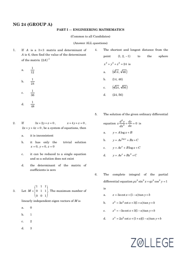
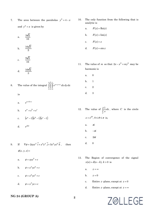
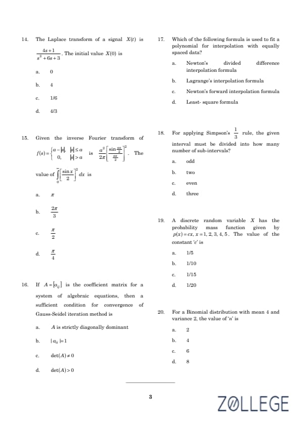

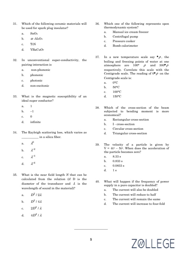
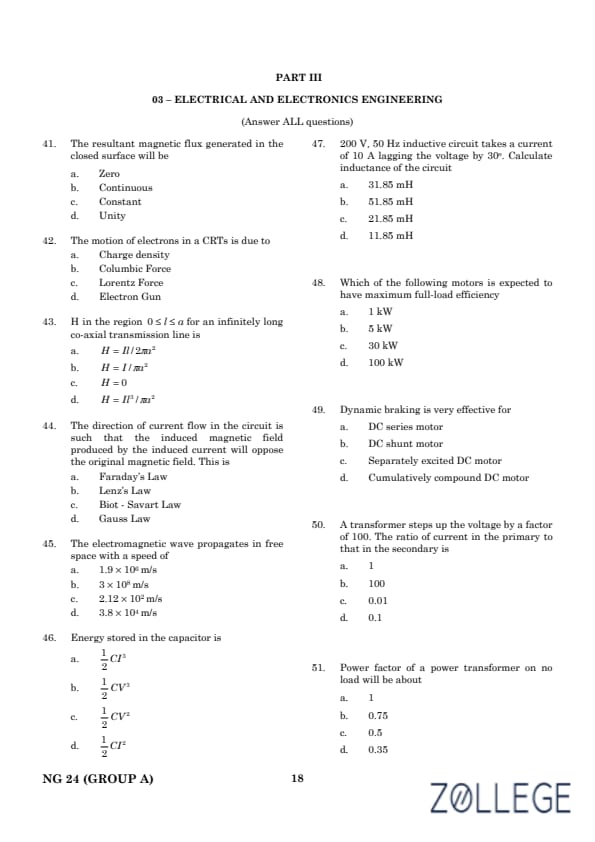
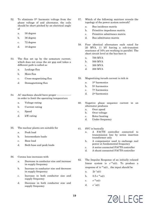
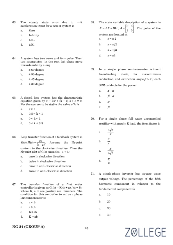
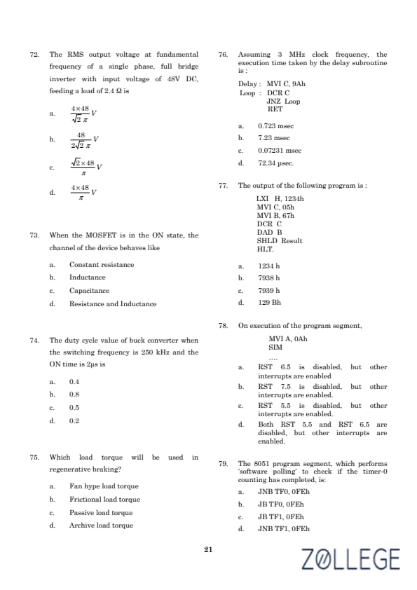
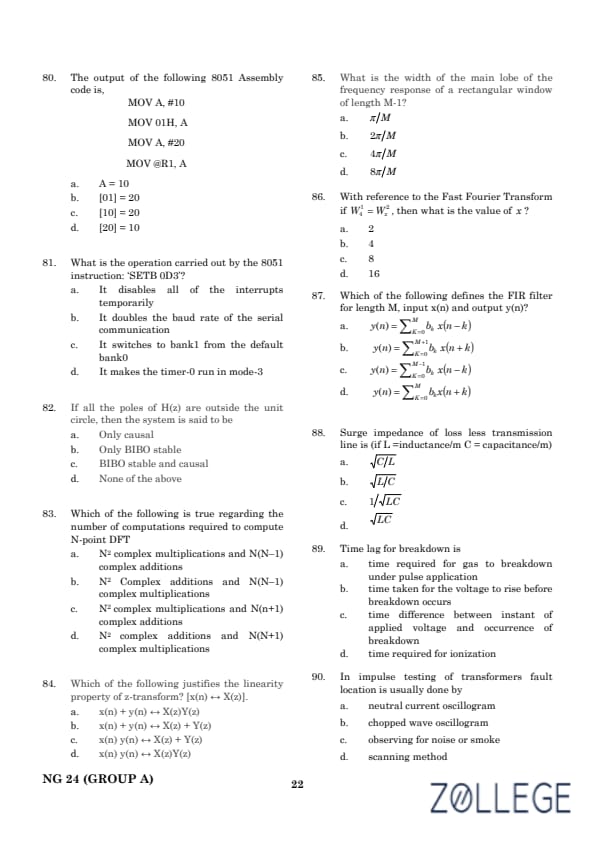
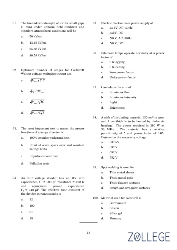
*The article might have information for the previous academic years, please refer the official website of the exam.