
CUET 2026 Physics Question Paper May 19 Shift 1 with Solution Pdf


| Updated On - May 19, 2026
CUET 2026 May 19 Shift 1 Physics Question Paper with Solution PDF is available here for download. NTA conducted CUET 2026 on May 19, Shift 1, from 9 AM to 12 PM in CBT Mode.
The CUET 2026 Physics Question Paper includes questions from topics such as Electrostatics & Current Electricity, Magnetism, Electromagnetic Induction, Semiconductors and Optics, with 50 Questions carrying a total of 250 marks. As per the CUET marking scheme, +5 marks are awarded for every correct answer, and -1 mark is deducted for every wrong answer.
CUET 2026 Physics Question Paper May 19 Shift 1 with Solution PDF
| CUET 2026 Physics Question Paper | Download PDF | Check Solutions |
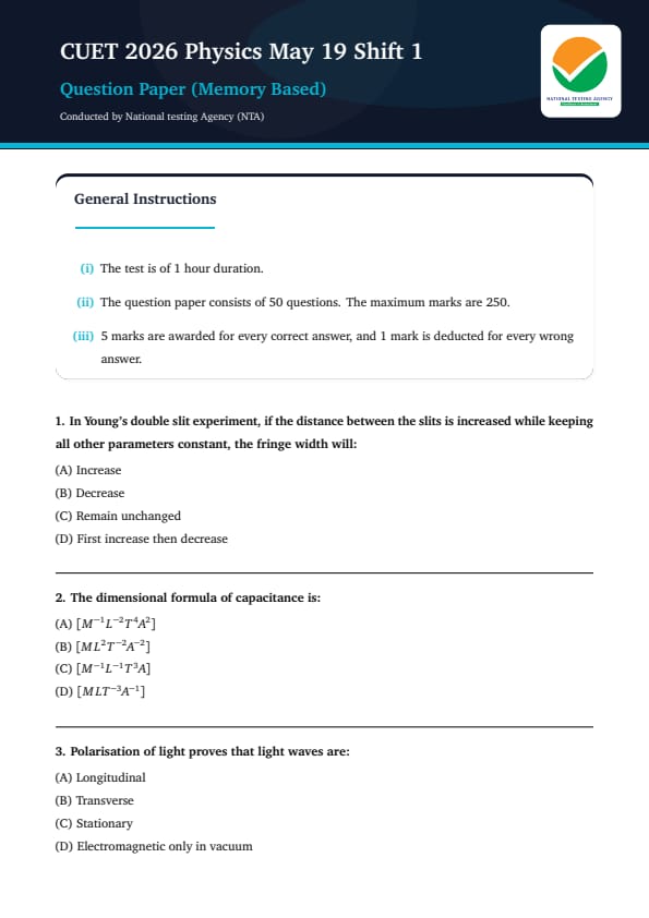
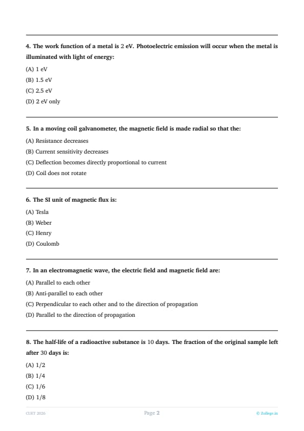
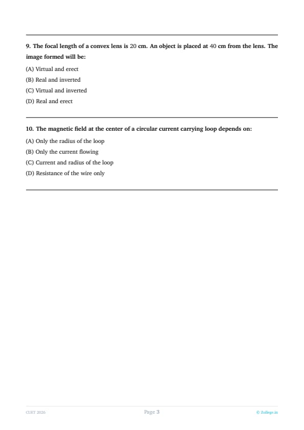
In Young’s double slit experiment, if the distance between the slits is increased while keeping all other parameters constant, the fringe width will:
View Solution
Step 1 : Understanding the Question:
The topic of this question is Wave Optics, specifically focusing on the phenomenon of Interference as demonstrated in Young's Double Slit Experiment (YDSE). This experiment is a fundamental proof of the wave nature of light, where two coherent sources produce a pattern of bright and dark bands known as fringes on a distant screen. The question asks for the mathematical and physical consequence of increasing the separation between the two slits on the width of these fringes, provided that the wavelength of light and the distance to the screen remain fixed.
Step 2 : Key Formulas and approach:
The approach involves using the standard expression for fringe width in a vacuum or air medium. The fundamental formula is:
\[ \beta = \frac{\lambda D}{d} \]
Where the variables are defined as:
1. \(\beta\) (Beta) represents the Fringe Width (distance between two consecutive bright or dark fringes).
2. \(\lambda\) (Lambda) represents the Wavelength of the monochromatic light source used.
3. \(D\) represents the distance between the plane of the slits and the observation screen.
4. \(d\) represents the distance between the two slits.
Step 3 : Detailed Explanation:
To understand the relationship, we look at the proportionality derived from the fringe width formula: \(\beta \propto \frac{1}{d}\).
This equation tells us that the fringe width (\(\beta\)) is inversely proportional to the separation between the slits (\(d\)).
When we "increase" the distance between the slits (\(d\)), the denominator in our primary equation becomes larger.
Mathematically, if the denominator of a fraction increases while the numerator (\(\lambda D\)) stays the same, the overall value of the fraction decreases.
Physically, this means that as the slits move further apart, the interference maxima and minima on the screen crowd closer together, making each individual fringe narrower.
Conversely, if the slits were brought closer together (\(d\) decreased), the interference pattern would expand, and the fringe width would increase.
Since the question specifically mentions that \(d\) is increased, the only logical result for the fringe width is a decrease.
Step 4 : Final Answer:
Because of the inverse proportionality between slit separation and fringe width, increasing the distance between the slits results in a decrease in the fringe width. Therefore, the correct option is (B).
Quick Tip: Think of the "Inverse Rule" for YDSE: Narrow Slits = Wide Pattern; Wide Slits = Narrow Pattern. If you pull the slits apart (\(d \uparrow\)), the fringes get squeezed together (\(\beta \downarrow\))!
The dimensional formula of capacitance is:
View Solution
Step 1 : Understanding the Question:
The topic of this question is Dimensional Analysis within the context of Electrostatics. Every physical quantity in physics can be expressed in terms of fundamental dimensions: Mass [M], Length [L], Time [T], and Electric Current [A]. Capacitance is the ability of a system to store an electric charge per unit of electric potential. To find its dimensional formula, we must break down its definition into these base fundamental units through a series of step-by-step derivations involving charge, work, and potential.
Step 2 : Key Formulas and approach:
We utilize the following fundamental relationships to derive the dimensions:
1. Capacitance: \(C = \frac{Q}{V}\) (Charge divided by Potential)
2. Electric Potential: \(V = \frac{W}{Q}\) (Work done per unit Charge)
3. Substituting \(V\) in \(C\): \(C = \frac{Q^2}{W}\)
4. Basic Units: Charge (\(Q\)) = Current (\(I\)) \(\times\) Time (\(t\)) and Work (\(W\)) = Force \(\times\) Displacement.
Step 3 : Detailed Explanation:
Step 1: Find dimensions of Charge [Q]. Since \(Q = I \times t\), the dimensional formula is \([A^1 T^1]\).
Step 2: Find dimensions of Work [W]. Work is Force (\(M L T^{-2}\)) multiplied by Displacement (\(L\)). Thus, \([W] = [M^1 L^2 T^{-2}]\).
Step 3: Derive dimensions of Potential [V]. Since \(V = \frac{W}{Q}\), we have \([V] = \frac{[M^1 L^2 T^{-2}]}{[A^1 T^1]} = [M^1 L^2 T^{-3} A^{-1}]\).
Step 4: Calculate Capacitance [C] using the formula \(C = \frac{Q}{V}\).
Step 5: Substitute the dimensions: \([C] = \frac{[A^1 T^1]}{[M^1 L^2 T^{-3} A^{-1}]}\).
Step 6: Move all terms to the numerator by changing the signs of the exponents: \([M^{-1} L^{-2} T^{1 - (-3)} A^{1 - (-1)}]\).
Step 7: Simplifying the exponents for Time and Current, we get \(T^4\) and \(A^2\).
The final resulting formula is \([M^{-1} L^{-2} T^4 A^2]\), which shows capacitance has an inverse relationship with mass and length but a direct relationship with the square of current and the fourth power of time.
Step 4 : Final Answer:
The derived dimensional formula for capacitance is \([M^{-1} L^{-2} T^4 A^2]\), which corresponds to option (A).
Quick Tip: To remember this quickly, use the code "-1, -2, 4, 2". Capacitance is a "heavy" storage unit, so it has high positive powers for Time (4) and Current (2), while Mass and Length are negative!
Polarisation of light proves that light waves are:
View Solution
Step 1 : Understanding the Question:
The topic of this question is Wave Optics, specifically focusing on the phenomenon of Polarization. Light exhibits various properties such as interference, diffraction, and polarization. While interference and diffraction confirm that light behaves like a wave, they do not distinguish whether those waves are longitudinal or transverse. Polarization is a unique property that restricts the vibrations of a wave to a specific plane. This question asks what this specific property reveals about the physical nature of light wave oscillations.
Step 2 : Key Formulas and approach:
The approach is conceptual rather than mathematical. It involves understanding the geometric constraints of different wave types:
1. Longitudinal Waves: Vibrations occur parallel to the direction of propagation (like sound). These are symmetrical around the axis of travel.
2. Transverse Waves: Vibrations occur perpendicular to the direction of propagation (like waves on a string).
3. Polarization Rule: Only waves with vibrations perpendicular to the direction of travel can be restricted to a single plane.
Step 3 : Detailed Explanation:
Longitudinal waves, such as sound waves in air, consist of compressions and rarefactions where particles move back and forth along the path of the wave. Because their motion is always along the direction of travel, there is no "side" to filter out; therefore, they cannot be polarized.
Transverse waves, however, have oscillations that occur in a plane perpendicular to the direction of the wave's velocity. These oscillations can be up-down, left-right, or at any angle in that perpendicular plane.
Polarization is the process of filtering these oscillations so that they only occur in one single direction (e.g., only vertical).
Experimentally, light can be polarized using materials like Polaroid filters or through reflection at specific angles (Brewster's Angle).
The fact that we can successfully block light by rotating two polarizers (cross-polarization) proves that light must have a specific orientation of oscillation that is perpendicular to its travel.
Thus, the ability of light to be polarized is the definitive evidence that light is a transverse wave.
Other phenomena like interference happen for both longitudinal and transverse waves, so they do not provide this specific proof.
Step 4 : Final Answer:
Since polarization is only possible for waves with perpendicular oscillations, it proves that light waves are Transverse. The correct option is (B).
Quick Tip: Remember the "Exclusivity Rule": Interference and Diffraction occur for ALL waves, but Polarization occurs ONLY for Transverse waves. If a wave can be polarized, it is 100% transverse!
The work function of a metal is \(2 eV\). Photoelectric emission will occur when the metal is illuminated with light of energy:
View Solution
Step 1 : Understanding the Question:
The topic of this question is the Photoelectric Effect, a key concept in Modern Physics and the Dual Nature of Radiation and Matter. This phenomenon involves the ejection of electrons from a metal surface when light of a sufficient frequency shines on it. The question provides the "work function" of a metal and asks us to identify which incident photon energy will successfully trigger the release of an electron. It tests the fundamental threshold condition required for the photoelectric effect to take place.
Step 2 : Key Formulas and approach:
We use Einstein’s photoelectric equation to understand the energy balance:
1. Einstein's Equation: \(E = \phi_0 + K_{max}\)
2. Threshold Condition: For emission to occur, \(E \ge \phi_0\).
Where:
- \(E\) is the energy of the incident photon.
- \(\phi_0\) (Phi) is the work function (the minimum energy required to liberate an electron).
- \(K_{max}\) is the maximum kinetic energy of the emitted photoelectron.
Step 3 : Detailed Explanation:
The work function (\(\phi_0\)) is a constant property of a specific metal. In this case, \(\phi_0 = 2 eV\).
This means every single electron is "bound" to the metal by an energy of at least \(2 eV\). To escape, it must receive at least this much energy from a single incoming photon.
If the incident light energy \(E\) is less than \(2 eV\), the electron will not have enough energy to break free from the metal's surface, and no emission will occur, regardless of how intense the light is.
Let's check the options: (A) \(1 eV\) is less than \(2 eV\), so no emission. (B) \(1.5 eV\) is also less than \(2 eV\), so no emission.
Option (C) \(2.5 eV\) is greater than the work function of \(2 eV\). This means the photon has enough energy to liberate the electron (\(2 eV\)) and still has some leftover energy (\(0.5 eV\)) which becomes the kinetic energy of the moving electron.
Option (D) "2 eV only" is incorrect because any energy equal to OR greater than the work function will cause emission. Emission is not restricted to just the threshold value.
Step 4 : Final Answer:
Since \(2.5 eV\) is the only provided value that exceeds the \(2 eV\) threshold of the work function, it is the only case where photoelectric emission occurs. The correct option is (C).
Quick Tip: Think of the work function as an "Escape Fee." If the fee to leave the metal is
(2.00 and you only have
)1.50, you can't leave. If you have
(2.50, you pay the
)2.00 fee and keep the
(0.50 as "spending money" (kinetic energy)!
In a moving coil galvanometer, the magnetic field is made radial so that the:
View Solution
Step 1 : Understanding the Question:
The topic of this question is Magnetic Effects of Current, specifically the design and operation of a Moving Coil Galvanometer (MCG). A galvanometer is an instrument used to detect and measure small electric currents. One of its critical design features is the use of a "radial magnetic field" created by concave magnetic poles and a soft iron core. The question asks why this specific field shape is necessary for the instrument's functionality.
Step 2 : Key Formulas and approach:
The approach involves analyzing the torque acting on a current-carrying loop in a magnetic field:
1. Deflecting Torque: \(\tau = NIAB \sin \theta\)
2. Restoring Torque: \(\tau = k \alpha\)
3. Goal: We want a linear relationship between the angular deflection (\(\alpha\)) and the current (\(I\)), which means we want \(\alpha \propto I\).
Where \(N\) is turns, \(I\) is current, \(A\) is area, \(B\) is magnetic field, \(\theta\) is the angle between the area vector and \(B\), and \(k\) is the spring constant.
Step 3 : Detailed Explanation:
In a standard uniform magnetic field, the torque depends on the sine of the angle \(\theta\). As the coil rotates, \(\theta\) changes, which means the torque would change even if the current \(I\) stayed the same. This would lead to a non-linear (logarithmic or sinusoidal) scale.
To make the galvanometer useful, we need a "linear scale" where a doubling of current results in exactly a doubling of the needle's deflection.
By making the magnetic field "radial," the magnetic field lines are always parallel to the plane of the coil (or perpendicular to the area vector) regardless of how much the coil has rotated.
This ensures that the angle \(\theta\) between the magnetic field and the normal to the coil is always \(90^\circ\). Since \(\sin 90^\circ = 1\), the torque formula simplifies to \(\tau = NIAB\).
At equilibrium, the deflecting torque equals the restoring torque of the spring: \(NIAB = k \alpha\).
Rearranging for deflection, we get \(\alpha = (\frac{NAB}{k}) I\). Since everything in the parentheses is constant, \(\alpha \propto I\).
This allows the manufacturer to mark the scale with equal divisions for equal current increments.
Step 4 : Final Answer:
The radial magnetic field ensures a constant torque by keeping \(\sin \theta = 1\), which makes the deflection directly proportional to the current. Thus, the correct option is (C).
Quick Tip: Radial Field = Constant Torque = Linear Scale. Without the radial field, your galvanometer would need a very complicated scale with uneven markings!
The SI unit of magnetic flux is:
View Solution
Step 1 : Understanding the Question:
The topic of this question is Magnetism and Electromagnetic Induction, specifically focusing on the measurement units of magnetic quantities. Magnetic flux is a measure of the total magnetic field that passes through a given area. It is conceptually similar to the "flow" of magnetic field lines through a surface. The question asks to identify the standard international (SI) unit used to quantify this flux.
Step 2 : Key Formulas and approach:
The approach involves looking at the mathematical definition of magnetic flux to see how its units are derived:
1. Formula: \(\Phi_B = B \cdot A \cdot \cos \theta\)
2. Unit Analysis: Flux Unit = (Unit of Magnetic Field) \(\times\) (Unit of Area).
3. Derived Unit: \(1 Flux Unit = 1 Tesla \cdot m^2\).
Step 3 : Detailed Explanation:
Magnetic Flux (\(\Phi_B\)) represents the product of the average magnetic field times the perpendicular area that it penetrates.
The SI unit for magnetic field (\(B\)) is the Tesla (T). The SI unit for area (\(A\)) is square meters (\(m^2\)).
Therefore, the unit for magnetic flux is Tesla-square meter (\(T \cdot m^2\)).
This derived unit is officially named the "Weber" (Wb) in the SI system, named after the German physicist Wilhelm Eduard Weber.
Let's check the other options to eliminate them: (A) Tesla is the unit for magnetic field intensity (B), not flux.
(C) Henry is the unit for Inductance (L), which relates to how flux changes with current.
(D) Coulomb is the unit for Electric Charge (Q).
Since the question specifically asks for magnetic flux, the Weber is the only correct choice. One Weber is defined as the amount of flux that, linking a circuit of one turn, produces in it an electromotive force of one volt if it is reduced to zero at a uniform rate in one second.
Step 4 : Final Answer:
The SI unit of magnetic flux is the Weber, which corresponds to option (B).
Quick Tip: Don't confuse "Field" with "Flux"! Magnetic Field = Tesla (Strength at a point). Magnetic Flux = Weber (Total lines through a window). Remember: \(Weber = Tesla \times Area\).
In an electromagnetic wave, the electric field and magnetic field are:
View Solution
Step 1 : Understanding the Question:
The topic of this question is Electromagnetic Waves (EM Waves). EM waves, such as light, radio waves, and X-rays, consist of oscillating electric and magnetic fields that travel through space. This question asks about the spatial orientation and geometric relationship between the oscillating electric field vector (\(\vec{E}\)), the oscillating magnetic field vector (\(\vec{B}\)), and the direction in which the wave is traveling (propagation).
Step 2 : Key Formulas and approach:
The approach is based on Maxwell’s equations and the transverse nature of electromagnetic radiation:
1. Transverse Nature: In EM waves, the fields do not oscillate along the direction of travel.
2. Cross Product Rule: The direction of propagation is given by the vector \(\vec{E} \times \vec{B}\).
3. Orthogonality: For a cross product to define a direction of travel, the components must be mutually perpendicular.
Step 3 : Detailed Explanation:
Electromagnetic waves are "transverse" waves. This means that the oscillations of the fields occur at right angles to the direction of energy transfer.
According to electromagnetic theory, an oscillating electric field creates an oscillating magnetic field, and vice-versa.
These two fields oscillate in phase (reaching peaks and zeros at the same time), but they do so in two different planes.
If the electric field oscillates along the Y-axis and the magnetic field oscillates along the Z-axis, the wave will propagate along the X-axis.
This creates a 3D coordinate system where the Electric Field, Magnetic Field, and the Direction of Propagation are all mutually perpendicular to each other. This is known as an orthogonal relationship.
If the fields were parallel, they would not be able to regenerate each other in space according to Maxwell’s equations, and the wave could not exist.
Therefore, the characteristic signature of an EM wave is this perpendicular arrangement.
Step 4 : Final Answer:
The electric field and magnetic field in an EM wave are perpendicular to each other and also perpendicular to the direction of propagation. The correct option is (C).
Quick Tip: Think of the "Rule of Three Rights": The E-field is at a right angle to the B-field, and both are at a right angle to the path of the wave. It's a perfect 3D corner!
The half-life of a radioactive substance is \(10\) days. The fraction of the original sample left after \(30\) days is:
View Solution
Step 1 : Understanding the Question:
The topic of this question is Nuclear Physics, specifically Radioactivity and the Law of Radioactive Decay. Radioactive substances are unstable and decay over time. The "half-life" is a fixed time interval during which exactly half of the remaining radioactive atoms in a sample will decay. The question asks us to calculate what portion (fraction) of the initial sample remains active after a specific duration that spans multiple half-lives.
Step 2 : Key Formulas and approach:
The approach involves calculating the number of half-life cycles that have passed:
1. Number of half-lives (\(n\)): \(n = \frac{Total Time}{Half-life}\)
2. Remaining Fraction formula: \(\frac{N}{N_0} = (\frac{1}{2})^n\)
Where \(N\) is the amount remaining and \(N_0\) is the initial amount.
Step 3 : Detailed Explanation:
First, we identify the given values: Half-life (\(T_{1/2}\)) = \(10\) days, and Total time (\(t\)) = \(30\) days.
Step 1: Calculate the number of half-life periods that occur within 30 days.
\(n = \frac{30}{10} = 3\) half-lives.
Step 2: Understand the decay process stage by stage.
After the 1st half-life (10 days): The sample becomes \(1/2\) of its original size.
After the 2nd half-life (20 days): Half of the \(1/2\) remains, which is \(1/4\) (\(1/2 \times 1/2\)).
After the 3rd half-life (30 days): Half of the \(1/4\) remains, which is \(1/8\) (\(1/4 \times 1/2\)).
Step 3: Use the formula to confirm: Fraction = \((\frac{1}{2})^3 = \frac{1}{8}\).
Note that radioactivity is a probabilistic process, so while we cannot predict when a single atom will decay, we can accurately predict the behavior of a large sample like this.
Step 4 : Final Answer:
After 30 days (which equals 3 half-lives), the remaining fraction of the radioactive substance is \(1/8\). Thus, the correct option is (D).
Quick Tip: Don't multiply \(1/2\) by 3! Half-life is an exponential process, not linear. Just keep dividing the remainder by 2 for every half-life that passes: \(1 \rightarrow 0.5 \rightarrow 0.25 \rightarrow 0.125\).
The focal length of a convex lens is \(20 cm\). An object is placed at \(40 cm\) from the lens. The image formed will be:
View Solution
Step 1 : Understanding the Question:
The topic of this question is Ray Optics, specifically focusing on Image Formation by Lenses. A convex lens is a converging lens that can form different types of images (real, virtual, magnified, or diminished) depending on the position of the object relative to the focal point (\(F\)) and the center of curvature (\(2F\)). The question gives us the focal length and the object distance and asks for the nature of the resulting image.
Step 2 : Key Formulas and approach:
The approach involves identifying the specific "Case" of image formation based on the object distance (\(u\)) and focal length (\(f\)):
1. Given: \(f = 20 cm\), \(u = 40 cm\).
2. Relationship: We observe that \(u = 2f\) (since \(40 = 2 \times 20\)).
3. Lens Formula (for confirmation): \(\frac{1}{v} - \frac{1}{u} = \frac{1}{f}\).
Step 3 : Detailed Explanation:
In optics, \(2f\) represents the center of curvature of the lens surface.
Case Analysis: When an object is placed exactly at \(2F\) of a convex lens, the rays of light converge on the other side of the lens at exactly the \(2F\) position.
Using the lens formula: \(\frac{1}{v} - \frac{1}{-40} = \frac{1}{20}\). This simplifies to \(\frac{1}{v} = \frac{1}{20} - \frac{1}{40} = \frac{1}{40}\). Thus, \(v = +40 cm\).
Nature of Image: Since the image distance (\(v\)) is positive, it means the image is formed on the side opposite to the object. The light rays physically meet at this point, making it a "Real" image.
Real images formed by a single lens are always "Inverted" (upside down).
Size: The magnification \(m = v/u = 40/(-40) = -1\). The negative sign confirms it is inverted, and the magnitude of 1 means it is the same size as the object.
Therefore, an object at \(2F\) produces a real and inverted image at \(2F\).
Step 4 : Final Answer:
Because the object is at \(2F\), the image is real and inverted. The correct option is (B).
Quick Tip: Remember the "2F rule" for convex lenses: Object at 2F \(\rightarrow\) Image at 2F. It's the "mirror point" where the image is the same size as the object and is always Real and Inverted!
The magnetic field at the center of a circular current carrying loop depends on:
View Solution
Step 1 : Understanding the Question:
The topic of this question is the Magnetic Effects of Current, specifically the magnetic field produced by a circular conductor. When an electric current flows through a circular loop, it generates a magnetic field in the surrounding space, with its maximum intensity being at the center of the loop. This question asks us to identify which physical variables determine the strength of this central magnetic field.
Step 2 : Key Formulas and approach:
The approach is to use the formula derived from the Biot-Savart Law for the magnetic field at the center of a circular loop:
1. Formula: \(B = \frac{\mu_0 I}{2r}\) (for a single turn)
2. Formula for \(N\) turns: \(B = \frac{\mu_0 N I}{2r}\)
Where \(B\) is the magnetic field, \(I\) is the current, \(r\) is the radius, and \(\mu_0\) is the permeability of free space.
Step 3 : Detailed Explanation:
According to the mathematical expression \(B = \frac{\mu_0 I}{2r}\), there are two primary physical variables that can change (assuming we stay in the same medium like air or vacuum).
Dependency 1: The magnetic field (\(B\)) is directly proportional to the current (\(I\)). If you increase the current flowing through the wire, the magnetic field strength at the center will increase linearly.
Dependency 2: The magnetic field (\(B\)) is inversely proportional to the radius (\(r\)). If you make the loop larger (increase radius), the field at the center becomes weaker because the current-carrying wire is physically further away from the center point.
Resistance (Option D) is not a direct factor in the field formula, though it affects the current if the voltage is fixed. However, the field itself is governed by the resulting current and geometry.
Therefore, to know the magnetic field at the center, one must know both how much current is flowing and how large the circle is.
Step 4 : Final Answer:
The magnetic field strength depends on both the current (\(I\)) and the radius of the loop (\(r\)). Therefore, the correct option is (C).
Quick Tip: Keep the formula \(B = \frac{\mu_0 I}{2r}\) in your head. It shows \(I\) on top (direct) and \(r\) on bottom (inverse). Both are needed to determine the total field strength!
CUET 2026 Physics Revision Marathon
*The article might have information for the previous academic years, please refer the official website of the exam.