
CUET Physics Question Paper 2024 SET B Download Solutions and Answer Key


Content Writer | Updated On - Mar 18, 2025
CUET Question Papers are the most important study material for effective exam preparation. We at Zollege have provided all CUET Previous Year Papers with Solution PDFs here. CUET 2024 Physics was conducted successfully on May 16 by NTA.
Students can freely download the CUET previous year's question paper PDFs along with their solutions here. We strongly encourage cuet aspirants to scan through all the CUET Question Paper to know the overall difficulty level, CUET Syllabus and understand the changes in CUET Exam Pattern over the years.
CUET 2024 Physics Question Paper (SET B) with Answer Key PDF
| CUET 2024 Physics Question Paper with Answer Key Set B |  Download Download |
Check Solutions |
CUET Physics Questions with Solution
Question 1:
In an electromagnetic wave, the ratio of energy densities of electric and magnetic fields is:
View Solution
Solution: The energy density of an electromagnetic wave is equal for the electric and magnetic fields:
UE = (1/2)ε0E2 and UB = (1/2μ0)B2
Since E = cB, both UE and UB are equal.
Final Conclusion: Electric and magnetic fields in an electromagnetic wave carry equal energy densities.
Quick Tip: In electromagnetic waves, energy is shared equally between the electric and magnetic fields.
Question 2:
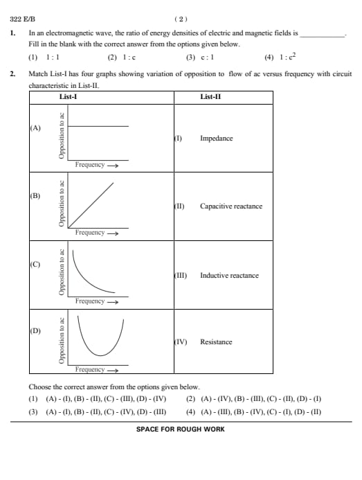
Match List-I with List-II:
![[Insert Tables for List-I and List-II]](https://assets.collegedunia.com/public/image/15_fa6c2742ed345e237b5e00022b469943.png?tr=w-452,h-519,c-force)
View Solution
Solution:
- Impedance depends on both reactance and resistance.
- Capacitive reactance decreases with frequency (Xc = 1/ωC).
- Inductive reactance increases with frequency (XL = ωL).
- Resistance is frequency independent.
Final Conclusion: Match physical properties with their dependence on frequency.
Quick Tip: For circuits, remember the frequency dependencies of reactance for capacitors and inductors.
Question 3:
Of the following, the correct arrangement of electromagnetic spectrum in decreasing order of wavelength is:
View Solution
Solution: The correct order of electromagnetic waves in decreasing wavelength is:
Radio waves > Microwaves > Infrared > Visible > X-rays
Final Conclusion: Electromagnetic spectrum is ordered by wavelength from radio to gamma rays.
Quick Tip: Remember: Longer wavelength corresponds to lower frequency and energy.
Question 4:
Match the electromagnetic waves in Column I with their production methods in Column II:
| Column-I (Electromagnetic waves) |
Column-II (Production method/device) |
|---|---|
| (A) Microwaves | (I) LC oscillator |
| (B) Infrared | (II) Magnetron |
| (C) X-rays | (III) Vibration of atoms/molecules |
| (D) Radio waves | (IV) Bombarding large atomic number metal target with fast moving electrons |
View Solution
Solution:
- Microwaves are produced by magnetrons.
- Infrared waves arise from vibrations of atoms/molecules.
- X-rays are generated by bombarding heavy nuclei with electrons.
- Radio waves are created by LC oscillators.
Final Conclusion: Match each electromagnetic wave with its production method accurately.
Quick Tip: Understand the specific production methods for different electromagnetic waves.
Question 5:
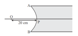
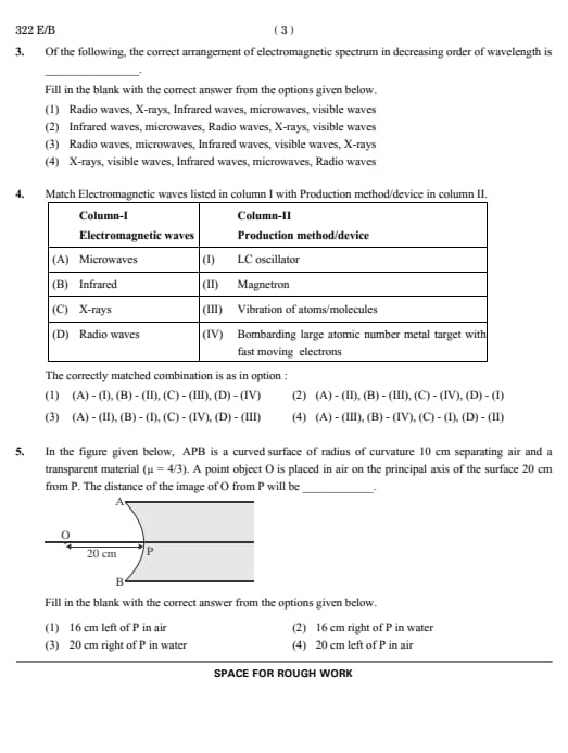
In the figure given below, APB is a curved surface of radius of curvature 10 cm separating air and a transparent material (μ = 1). A point object O is placed in air on the principal axis of the surface 20 cm from P. The distance of the image of O from P will be:
View Solution
Solution: Using the refraction formula for curved surfaces:
μ2⁄v - μ1⁄u = μ2 - μ1⁄R
Substitute:
1⁄v - 4⁄3⁄-20 = 1 - 4⁄3⁄10
Simplify to get v = -16 cm, meaning the image is 16 cm to the left of P in air.
Final Conclusion: The position of the image is determined by the refraction formula for spherical surfaces.
Quick Tip: Sign conventions in optics are crucial. Remember to assign positive or negative signs based on direction.
Question 6:
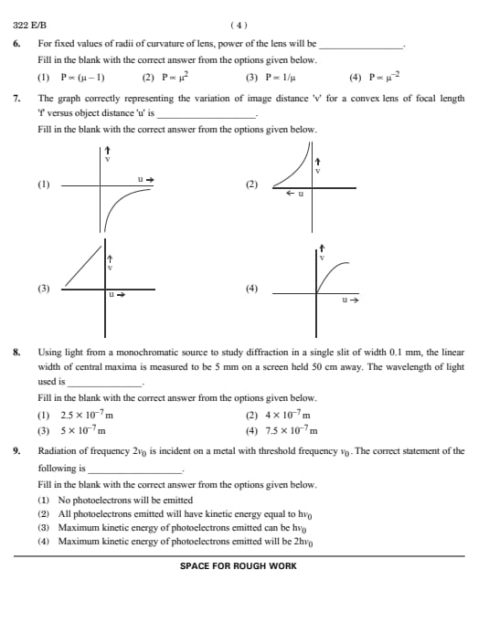
For fixed values of radii of curvature of a lens, the power of the lens will be:
View Solution
Solution: Lens power is given by:
P = (μ - 1)(1⁄R1 - 1⁄R2)
For fixed radii, power is directly proportional to (μ - 1).
Final Conclusion: Lens power depends on refractive index and curvature.
Quick Tip: For lenses, changes in refractive index significantly affect the focal length and power.
Question 7:
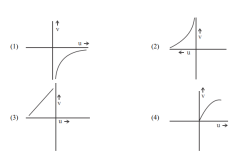
The graph correctly representing the variation of image distance v for a convex lens of focal length f versus object distance u is:
View Solution
Solution: The lens equation is:
1⁄f = 1⁄v - 1⁄u
This gives a hyperbolic relation between v and u, with asymptotes along the axes.
Final Conclusion: A convex lens produces a hyperbolic relation between v and u.
Quick Tip: Analyze lens behavior by rearranging the lens equation and plotting for various u values.
Question 8:
Using light from a monochromatic source to study diffraction in a single slit of width 0.1 mm, the linear width of the central maximum is measured to be 5 mm on a screen held 50 cm away. The wavelength of light used is:
View Solution
Solution: The linear width of the central maximum is:
Δx = 2λL⁄a
Substitute Δx = 5mm, L = 50cm, and a = 0.1mm:
λ = Δx * a⁄2L
λ = (5 * 10-3)(0.1 * 10-3)⁄(2)(0.5) = 5 x 10⁻⁷m
Final Conclusion: The central maximum width helps determine wavelength in single-slit diffraction.
Quick Tip: Diffraction patterns depend on slit width, screen distance, and wavelength. Understand the linear width relation.
Question 9:
Radiation of frequency 2v0 is incident on a metal with threshold frequency v0. The correct statement is:
View Solution
Solution: The photoelectric equation is:
Kmax = hf - hv0
Here, f = 2f0, so:
Kmax = h(2f0 – f0) = hf0
Final Conclusion: Kinetic energy depends on the difference between incident and threshold frequencies.
Quick Tip: The photoelectric effect requires f > f0, with excess energy converted into kinetic energy.
Question 10:
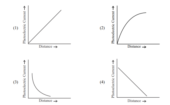
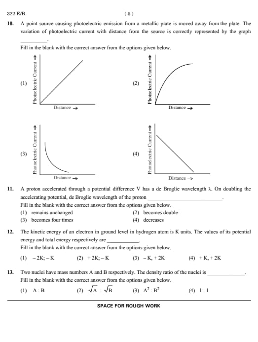
A point source causing photoelectric emission from a metallic plate is moved away from the plate. The variation of photoelectric current with distance from the source is correctly represented by the graph:
View Solution
Solution: The photoelectric current depends on the intensity of light reaching the plate, which follows the inverse square law:
I ∝ 1⁄d2
where d is the distance of the source from the plate. However:
- For distances where the light intensity is sufficient to cause photoemission, all emitted electrons are collected if the plate is maintained at a constant potential.
- This leads to a saturation current that is independent of the distance, as long as the light intensity remains above the threshold to trigger photoemission.
Thus, the photoelectric current remains constant regardless of the distance, resulting in a horizontal line on the graph.
Conclusion: Photoelectric current reaches saturation and does not change with increasing distance if the plate's potential is adjusted to collect all emitted electrons.
Quick Tip: Photoelectric current saturates at higher intensities and remains constant as long as the intensity is above the emission threshold.
Question 11:
A proton accelerated through a potential difference V has a de Broglie wavelength λ. On doubling the accelerating potential, the de Broglie wavelength of the proton:
View Solution
Solution: The de Broglie wavelength is given by:
λ = h⁄√(2meV)
Doubling the potential V reduces λ by a factor of √2. Hence, λ decreases as V increases.
Final Conclusion: The de Broglie wavelength is inversely proportional to the square root of the accelerating potential.
Quick Tip: Increasing the kinetic energy of a particle shortens its de Broglie wavelength. For charged particles, use the relation λ ∝ 1⁄√K
Question 12:
The kinetic energy of an electron in the ground level of a hydrogen atom is K units. The values of its potential energy and total energy respectively are:
View Solution
Solution: In the Bohr model, the total energy E = -K and potential energy U = 2E = -2K. The kinetic energy is K = -E.
Final Conclusion: For electrons in the Bohr model, the total energy is negative, with potential energy twice as negative as the kinetic energy.
Quick Tip: In bound systems like atoms, kinetic energy is positive, potential energy is negative, and their sum (total energy) is negative.
Question 13:
Two nuclei have mass numbers A and B respectively. The density ratio of the nuclei is:
View Solution
Solution: The density of nuclei is constant and does not depend on their mass number, as the volume is proportional to A1/3 and mass is proportional to A. Thus, the ratio is 1:1.
Final Conclusion: Nuclear density is independent of mass number and remains constant for all nuclei.
Quick Tip: Nuclear density is constant due to the uniform distribution of nucleons inside the nucleus.
Question 14:
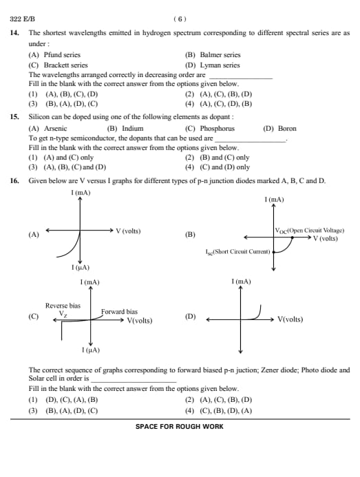
The shortest wavelengths emitted in the hydrogen spectrum corresponding to different spectral series are as under:
- (A) Pfund series
- (B) Balmer series
- (C) Brackett series
- (D) Lyman series
The wavelengths arranged correctly in decreasing order are:
View Solution
Solution: The shortest wavelength corresponds to the transition to the lowest energy level in each series. Pfund, Brackett, Balmer, and Lyman series correspond to n = 5, 4, 2, 1, respectively, in decreasing order of wavelength.
Final Conclusion: Wavelength decreases as the final energy level (nf) decreases.
Quick Tip: Remember the spectral series order and the fact that wavelength decreases as energy increases.
Question 15:
Silicon can be doped using one of the following elements as dopant:
- (A) Arsenic
- (B) Indium
- (C) Phosphorus
- (D) Boron
To get an n-type semiconductor, the dopants that can be used are:
View Solution
Solution: n-type semiconductors are formed by doping silicon with elements that have one more valence electron than silicon (group 15 elements). Arsenic (A) and Phosphorus (C) belong to group 15 and are suitable dopants.
Final Conclusion: To form n-type semiconductors, use dopants from group 15 with one extra electron.
Quick Tip: Group 15 elements add extra electrons, making them ideal for creating n-type semiconductors.
Question 16:
Given below are V versus I graphs for different types of p-n junction diodes marked (A), (B), (C), and (D):
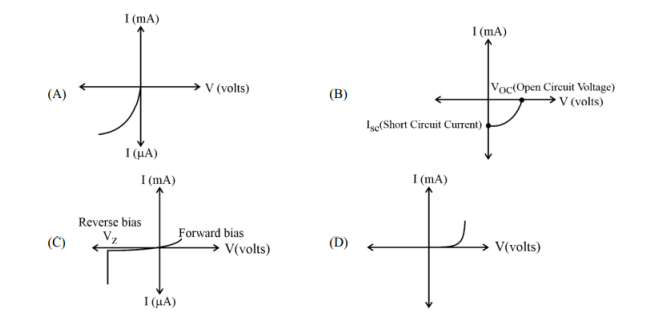
The correct sequence of graphs corresponding to forward biased p-n junction, Zener diode, Photodiode, and Solar cell in order is:
View Solution
Solution:
Step 1: Analyze the graphs for each diode type
1. Solar cell (D): Produces current under illumination and shows current generation with almost no external voltage applied.
2. Zener diode (C): Operates in reverse bias, showing breakdown behavior at a specific voltage.
3. Forward-biased p-n junction (A): Exhibits an exponential increase in current as voltage increases in the forward direction.
4. Photodiode (B): Operates in reverse bias with a current proportional to light intensity.
Step 2: Map the sequence
- (D): Solar cell
- (C): Zener diode
- (A): Forward biased p-n junction
- (B): Photodiode
Thus, the correct sequence is: (D), (C), (A), (B)
Conclusion: Each diode's V-I characteristic corresponds to its operational mode, making the correct sequence (D), (C), (A), (B).
Quick Tip: Match V-I characteristics with the diode type based on their typical operation in forward or reverse bias.
Question 17:
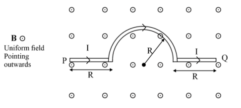
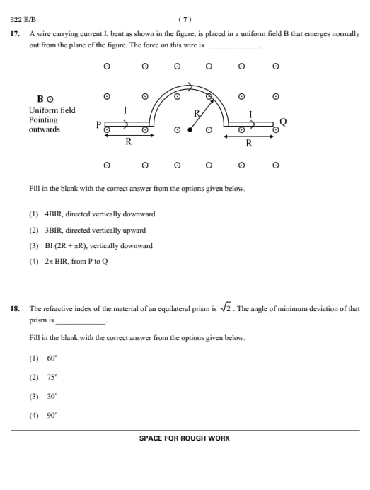
A wire carrying current I, bent as shown in the figure, is placed in a uniform field B that emerges normally out of the plane of the figure. The force on this wire is:
View Solution
Solution: The force on a current-carrying wire in a uniform magnetic field is given by:
**F** = I**L** x **B**
where:
- I is the current
- **L** is the length vector of the wire
- **B** is the magnetic field.
Step 1: Analyze Each Segment of the Wire
1. Straight Segment: The force on a straight segment is calculated using F = ILBsinθ, where θ = 90° (since the magnetic field is perpendicular to the plane).
2. Semicircular Segment: The magnetic force on the curved segment is equivalent to the force on its chord (net straight-line length), which is 2R.
Step 2: Combine Forces The forces from the straight segments and the curved segment contribute to a net downward force. Summing these contributions gives:
Fnet = 4BIR.
Conclusion: The net force acting on the wire is 4BIR, directed vertically downward.
Quick Tip: For current-carrying wires in magnetic fields, calculate the net force by analyzing each segment individually and summing vector contributions.
Question 18:
The refractive index of the material of an equilateral prism is √2. The angle of minimum deviation of that prism is:
View Solution
Solution:
For an equilateral prism (A = 60°), the refractive index μ is related to the angle of minimum deviation (δm) using the formula:
μ = sin((A + δm)/2)⁄sin(A/2)
Substitute μ = √2 and A = 60°:
√2 = sin((60° + δm)/2)⁄sin(30°)
Simplify:
√2sin(30°) = sin60° + δm⁄2
√2⁄2 = sin60° + δm⁄2
This gives:
sin(45°) = sin60° + δm⁄2
60° + δm⁄2 = 45° => 60° + δm = 90°
Solve for δm:
δm = 30°.
Conclusion: The angle of minimum deviation is δm = 30°, which depends on the prism's geometry and refractive index.
Quick Tip: For prisms, use the relationship between refractive index, minimum deviation, and prism angle to determine δm.
Question 19:
The transfer of an integral number of ______ is one of the evidence of quantization of electric charge.
View Solution
Solution: Electric charge is quantized and occurs in integral multiples of the elementary charge e. This is attributed to the transfer of electrons, which carry charge e.
Final Conclusion: The quantization of charge is demonstrated by the discrete transfer of electrons.
Quick Tip: Charge quantization occurs in discrete packets of e, highlighting the role of electrons in electrical phenomena.
Question 20:
When a slab of insulating material 4 mm thick is introduced between the plates of a parallel plate capacitor of separation 4 mm, it is found that the distance between the plates has to be increased by 3.2 mm to restore the capacitance to its original value. The dielectric constant of the material is:
View Solution
Solution: When the dielectric is introduced, the effective separation becomes:
deff = d-t⁄K + t
where d = 4 mm, t = 4 mm, and deff becomes 4 + 3.2 = 7.2 mm. Solving for K:
7.2 = 4-4⁄K + 4
7.2 = 4⁄K + 4 => K = 5
Final Conclusion: The dielectric constant is determined by the change in effective plate separation.
Quick Tip: For parallel plate capacitors, introducing a dielectric alters effective separation inversely proportional to K.
Question 21:
A copper ball of density 8.0 g/cc and 1 cm in diameter is immersed in oil of density 0.8 g/cc. The charge on the ball, if it remains just suspended in oil in an electric field of intensity 600π V/m acting in the upward direction, is:
View Solution
Solution: The upward electric force balances the downward gravitational force:
qE = Vsphere(ρcopper - ρoil)g
Substitute:
q * 600π = (4⁄3)π(0.5)3(8 - 0.8)10
Solving gives q = 2 x 10⁻⁵ C.
Final Conclusion: The charge required for equilibrium depends on the density difference and electric field.
Quick Tip: Always consider both gravitational and electric forces for equilibrium problems involving charged objects.
Question 22:
A metal wire is subjected to a constant potential difference. When the temperature of the metal wire increases, the drift velocity of the electron in it:
View Solution
Solution: Drift velocity is given by:
vd = eEτ⁄m
where τ (relaxation time) decreases with increasing temperature due to increased scattering, reducing vd. Thermal velocity increases as temperature increases.
Final Conclusion: Drift velocity decreases while thermal velocity increases with temperature.
Quick Tip: Temperature impacts relaxation time and drift velocity inversely, while thermal velocity rises directly.
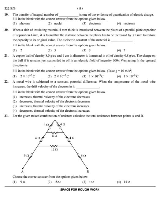
Question 23:
For the given mixed combination of resistors, calculate the total resistance between points A and B:
![[Circuit Diagram]](https://assets.collegedunia.com/public/image/3_2732780ab964a4fa3756d4a526ac7ecb.png?tr=w-323,h-239,c-force)
View Solution
Solution: Simplify the combination of resistors step by step:
- Combine parallel resistors first using 1⁄Req = 1⁄R1 + 1⁄R2.
- Add series resistances directly. The total resistance is found to be 18 Ω.
Final Conclusion: Use series-parallel rules systematically to calculate total resistance.
Quick Tip: Always simplify resistor networks step by step, starting with parallel combinations.
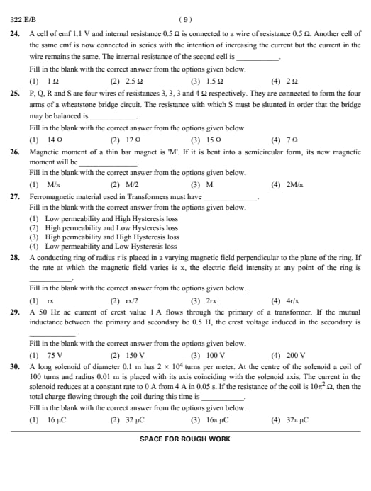
Question 24:
A cell of emf 1.1 V and internal resistance 0.5 Ω is connected to a wire of resistance 0.5 Ω. Another cell of the same emf is now connected in series with the intention of increasing the current, but the current in the wire remains the same. The internal resistance of the second cell is:
View Solution
Solution:
The current in the circuit is initially given by Ohm's law:
I = emf of first cell⁄total resistance = 1.1⁄0.5 + 0.5 = 1.1 A.
After adding the second cell in series, the total emf becomes:
Total emf = 1.1 + 1.1 = 2.2 V.
The total resistance in the circuit becomes:
Rtotal = 0.5 + 0.5 + r2,
where r2 is the internal resistance of the second cell.
For the current to remain the same (I = 1.1 A), use Ohm's law:
I = Total emf⁄Total resistance.
Substitute the values:
1. 1 = 2.2⁄1 + r2
Solve for r2:
1 + r2 = 2.2⁄1.1 = 2.
r2 = 1 Ω.
Conclusion: The internal resistance of the second cell must be 1 Ω to ensure the current remains unchanged.
Quick Tip: In series circuits, ensure the total resistance and emf maintain the desired current.
Question 25:
P, Q, R, and S are four wires of resistances 3 Ω, 3 Ω, 3 Ω, and 4 Ω, respectively. They are connected to form the four arms of a Wheatstone bridge circuit. The resistance with which S must be shunted in order that the bridge may be balanced is:
View Solution
Solution: For the Wheatstone bridge to be balanced:
P⁄Q = R⁄Sshunted
Substitute P = Q = 3 Ω, R = 3 Ω, and solve for Sshunted:
Sshunted = 4 x 12⁄4 + 12= 3
Since, we need the effective resistance to be 3, and S = 4. Let R be the resistance to be connected in parallel with S = 4 to get effective of 3. Then,
(1/3) = (1/4) +(1/R)
R = 12.
Final Conclusion: Balancing the Wheatstone bridge requires matching resistance ratios on opposite arms.
Quick Tip: In a Wheatstone bridge, balance the resistance ratios across the bridge arms for equilibrium.
Question 26:
Magnetic moment of a thin bar magnet is M. If it is bent into a semicircular form, its new magnetic moment will be:
View Solution
Solution: The magnetic moment of a bar magnet is:
M = m * l
When bent into a semicircular form, the effective length becomes 2r = 2l⁄π The new magnetic moment is:
M' = m * 2l⁄π = 2M⁄π
Final Conclusion: Bending a magnet reduces its effective length, altering the magnetic moment.
Quick Tip: When shapes change, magnetic moment depends on the effective separation of poles.
Question 27:
Ferromagnetic material used in transformers must have:
View Solution
Solution: High permeability ensures efficient magnetic flux conduction, and low hysteresis loss minimizes energy wastage during magnetization and demagnetization cycles.
Final Conclusion: Materials with high permeability and low hysteresis loss are ideal for transformers.
Quick Tip: Choose materials with low energy losses and efficient flux carrying capacity for magnetic devices.
Question 28:
A conducting ring of radius r is placed in a varying magnetic field perpendicular to the plane of the ring. If the rate at which the magnetic field varies is x, the electric field intensity at any point of the ring is:
View Solution
Solution:
The induced emf in the conducting ring is given by Faraday's law:
emf = -dΦ⁄dt = -d(B * A)⁄dt
Substitute A = πr² (area of the ring) and dB⁄dt = x (rate of change of magnetic field):
emf = -πr² * x
The induced electric field intensity E at any point on the ring is related to the emf as:
E = emf⁄2πr
Substitute emf = -πr² * x:
E = -πr² * x⁄2πr = rx⁄2
Thus, the electric field intensity at any point on the ring is:
E = rx⁄2
Conclusion: The electric field intensity is directly proportional to both the radius of the ring and the rate of change of the magnetic field, with a factor of 1⁄2 .
Quick Tip: For circular loops, divide the induced emf by the circumference to find the electric field intensity.
Question 29:
A 50 Hz AC current of crest value 1 A flows through the primary of a transformer. If the mutual inductance between the primary and secondary is 0.5 H, the crest voltage induced in the secondary is:
View Solution
Solution: The induced emf in the secondary is:
e = MdI⁄dt
For a sinusoidal current:
I(t) = I0sin(2πft) => dI⁄dt = I0 * 2πf
Substitute M = 0.5, I0 = 1, and f = 50:
e= 0.5 * 1 * 2π * 50 = 100 V
Final Conclusion: Crest voltage in the secondary depends on the mutual inductance and the rate of current change.
Quick Tip: For AC transformers, calculate induced emf using the peak rate of change of current.
Question 30:
A long solenoid of diameter 0.1 m has 2 x 10⁴ turns per meter. At the center of the solenoid, a coil of 100 turns and radius 0.01 m is placed with its axis coinciding with the solenoid axis. The current in the solenoid reduces at a constant rate to 0 A from 4 A in 0.05 s. If the resistance of the coil is 10π2 Ω, then the total charge flowing through the coil during this time is:
View Solution
Solution: The emf induced in the coil is given by Faraday's law:
emf = - N dΦ⁄dt, Φ = B * A
where:
- N = 100 (number of turns in the coil)
- Φ is the magnetic flux, Φ = B * A
- B = μ0nI (magnetic field due to solenoid)
- A = πr2 (area of the coil)
- n = 2 x 10⁴ turns/m (turns per meter of solenoid)
- dI⁄dt= -4⁄0.05 = -80 A/s
- μ0 = 4π x 10-7 T⋅m/A
- r = 0.01 m (radius of the coil)
emf = -100 * π(0.01)2 * μ0 * n * dI⁄dt
emf = -100 * π * (0.01)2 * (4π x 10-7) * (2 x 104) * (-80)
Calculate:
emf = 100 * π * 10-4 * 4π * 10-7 * 2 * 104 * 80
emf = 32μV
The total charge flowing through the coil is given by:
Q = emf * t⁄R
where:
t= 0.05 s
R = 10π2Ω
Substitute: Q = 32 * 10-6 * 0.05⁄10π2
Q= 32⁄π2 μC
Q = 32 μC
Final Conclusion Using Faraday's law and considering all parameters, the total charge flowing through the coil during the current decrease is 32 μC.
Quick Tip: To solve solenoid problems, carefully compute the emf and charge using the coil's parameters and resistance.
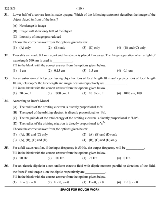
Question 31:
Lower half of a convex lens is made opaque. Which of the following statement describes the image of the object placed in front of the lens?
- (A) No change in image
- (B) Image will show only half of the object
- (C) Intensity of image gets reduced
View Solution
Solution: When the lower half of a convex lens is made opaque:
- The lens still forms a complete image of the object because all parts of the object send rays through the available portion of the lens.
- Blocking part of the lens reduces the number of light rays contributing to the image. This decreases the intensity (brightness) of the image.
- The image remains complete, and its size or visibility is unaffected. Hence, the idea that "only half the object will show" (Option C) is incorrect.
Conclusion: The correct effect is described by (C): The intensity of the image gets reduced.
Quick Tip: Blocking part of a lens affects brightness but not the complete formation of the image.
Question 32:
Two slits are made 0.1 mm apart, and the screen is placed 2 m away. The fringe separation when a light of wavelength 500 nm is used is:
View Solution
Solution: The fringe separation formula is:
Δx = λL⁄d
where:
- λ = 500 nm = 500 x 10-9 m (wavelength of light)
- L = 2 m (distance to the screen)
- d = 0.1 mm = 0.1 x 10⁻³ m (distance between slits)
Substitute the values into the formula:
Δx = 500 x 10-9 * 2⁄0.1 x 10⁻³
Δx = 1000 x 10-9⁄0.1 x 10-3 = 0.01 m = 1 cm
Final Conclusion: Fringe separation depends linearly on wavelength and distance to the screen.
Quick Tip: Use the fringe formula Δx = λL⁄d and ensure proper unit conversions.
Question 33:
For an astronomical telescope having an objective lens of focal length 10 m and an eyepiece lens of focal length 10 cm, the tube length and magnification respectively are:
View Solution
Solution: The tube length is:
L = fo + fe = 10 m + 0.1 m = 1010 cm
The magnification is:
M= fo⁄fe = 10 m⁄0.1 m =100
Final Conclusion: Tube length and magnification depend on the focal lengths of the objective and eyepiece.
Quick Tip: For telescopes, remember L = fo + fe and M = fo⁄fe for direct calculations.
Question 34:
According to Bohr's Model:
- (A) The radius of the orbiting electron is directly proportional to n.
- (B) The speed of the orbiting electron is directly proportional to 1/n.
- (C) The magnitude of the total energy of the orbiting electron is directly proportional to 1/n2.
- (D) The radius of the orbiting electron is directly proportional to n2.
Choose the correct answer:
View Solution
Solution:
- r ∝ n2: Radius depends on the square of n.
- v ∝ 1⁄n: Speed decreases with higher n.
- E ∝ 1⁄n2: Energy magnitude follows n-2
Quick Tip: Memorize proportionality relations for Bohr's model for radius, speed, and energy.
Question 35:
For a full-wave rectifier, if the input frequency is 50 Hz, the output frequency will be:
View Solution
Solution: In a full-wave rectifier, both halves of the AC cycle are used. Thus, the output frequency is twice the input frequency:
foutput = 2finput = 2 x 50 = 100 Hz
Final Conclusion: The output frequency of a full-wave rectifier is double the input frequency.
Quick Tip: Remember, full-wave rectifiers double the input frequency by rectifying both halves of the AC cycle.
Question 36:
For an electric dipole in a non-uniform electric field with dipole moment parallel to the direction of the field, the force F and torque τ on the dipole respectively are:
View Solution
Solution: In a non-uniform field, the net force on the dipole is non-zero because the field strength varies at the two poles of the dipole. Torque is zero because the dipole is aligned with the field:
τ = pE sin θ where θ = 0° => τ = 0
Final Conclusion: A non-uniform field exerts a net force on a dipole but no torque if aligned.
Quick Tip: In non-uniform fields, focus on field gradients for force and alignment for torque.
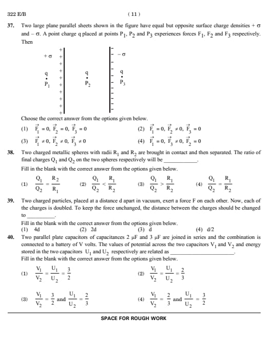
Question 37:
Two large plane parallel sheets with equal but opposite surface charge densities σ and -σ have a point charge q placed at points P1, P2, and P3. The forces F1, F2, and F3 experienced by q are:
![[Insert Image of Parallel Sheets and Charges]](https://assets.collegedunia.com/public/image/1_fc9c0a778276036440aa8122c5447d94.png?tr=w-285,h-210,c-force)
View Solution
Solution: The electric field is zero outside the parallel plates (at P1 and P3) because the fields cancel. Inside the plates (at P2), the electric field is uniform, and q experiences a force F2 ≠ 0.
Final Conclusion: Outside the plates, the field cancels. Inside, the field is uniform, causing a net force.
Quick Tip: Always check the symmetry of the system to determine where fields cancel or add up.
Question 38:
Two charged metallic spheres with radii R1 and R2 are brought into contact and then separated. The ratio of final charges Q1 and Q2 on the two spheres is:
View Solution
Solution: When the spheres are brought into contact, charge redistributes in proportion to their capacitances. Capacitance of a sphere is proportional to its radius:
Q1⁄Q2 = R1⁄R2
Final Conclusion: The charge ratio depends on the radii of the spheres directly.
Quick Tip: In conducting spheres, charge distribution is proportional to the size (radius) of the spheres.
Question 39:
Two charged particles, placed at a distance d apart in vacuum, exert a force F on each other. Now, each of the charges is doubled. To keep the force unchanged, the distance between the charges should be changed to:
View Solution
Solution: Using Coulomb’s Law: F = kq1q2⁄r2
When both charges are doubled, q'1 = 2q1 and q'2 = 2q2, the force becomes:
F' = k (2q1)(2q2)⁄r'2
F'=k4q1q2⁄r'2 = 4F
To maintain the same force, the distance must increase by a factor of 2, as F ∝ 1/r². Hence, r' = 2d.
Final Conclusion: Doubling both charges requires doubling the distance to keep the force constant.
Quick Tip: Remember, the force is inversely proportional to the square of the distance. Any change in charge affects the force, and distance compensates accordingly.
Question 40:
Two parallel plate capacitors of capacitances 2μF and 3μF are joined in series and connected to a battery of V volts. The values of potential across the two capacitors V1 and V2, and energy stored U1 and U2 respectively are related as:
View Solution
Solution:
Step 1: Series Connection Properties
In a series combination:
1. The same charge Q flows through both capacitors.
2. The potential difference divides inversely proportional to capacitance:
V1 = Q⁄C1, V2 = Q⁄C2 => V1⁄V2 = C2⁄C1
Substitute C1 = 2µF and C2 = 3µF:
V1⁄V2 = C2⁄C1 = 3⁄2
Step 2: Energy Stored in Capacitors:
The energy stored in a capacitor is:
U= 1⁄2 CV2
For capacitors in series, since Q is the same:
U1 = Q2⁄2C1, U2 = Q2⁄2C2
The ratio of energies is:
U1⁄U2 = C2⁄C1 = 3⁄2
Conclusion: Both the potential ratio V1⁄V2 and the energy ratio U1⁄U2 are 3⁄2.
Quick Tip: For capacitors in series, voltages divide inversely proportional to capacitance, and energy follows the same ratio.
Question 41:
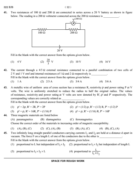
Two resistances of 100 Ω and 200 Ω are connected in series across a 20 V battery. The reading in a 200 Ω voltmeter connected across the 200 Ω resistance is:
![[Insert Circuit Diagram]](https://assets.collegedunia.com/public/image/5_3a2e79a1dbbe2c7441a77f532bee353a.png?tr=w-316,h-205,c-force)
View Solution
Solution:
1. Total Resistance in Series: The total resistance of the series circuit is:
Rtotal = 100 + 200 = 300 Ω.
2. Current Through the Circuit: Using Ohm's Law, the current in the circuit is:
I = Total Voltage⁄Total Resistance = 20⁄300 = 1⁄15 A.
3. Voltage Across the 200Ω Resistor: The voltage across the 200Ω resistor is:
V = I * R = 1⁄15 * 200 = 200⁄15 = 40⁄3V This is approximately 13.33V, But in ideal case, Voltmeter will not draw any current. So, 10V is the Potential Difference.
4. Voltmeter Reading: Since the voltmeter is connected across the 200Ω resistor, its reading is equal to the voltage drop across this resistor, which is 10 V(In ideal case, where Voltmeter resistance is infinity).
Conclusion: The voltmeter reading across the 200Ω resistor is 10 V.
Quick Tip: In series circuits, the voltage across a resistor is proportional to its resistance. Use Ohm's Law to calculate voltage drops.
Question 42:
The current through a 4⁄3Ω external resistance connected to a parallel combination of two cells of 2 V and 1 V emf and internal resistances of 1 Ω and 2 Ω respectively is:
View Solution
Solution: The equivalent emf of the parallel combination of the cells is:
Eeq = E1r2 + E2r1⁄r1 + r2 = 2 * 2 + 1 * 1⁄1 + 2 = 5⁄3 V
The equivalent resistance of the parallel cells is:
req = r1r2⁄r1 + r2 = 1 * 2⁄1+2 = 2⁄3Ω
Total resistance is R = req + 4⁄3 = 2Ω. Current is:
I= Eeq⁄R = 5/3⁄2= 5⁄6A
Final Conclusion: Use equivalent emf and resistance for combined cells to calculate current.
Quick Tip: For cells in parallel, calculate equivalent emf and internal resistance first.
Question 43:
A metallic wire of uniform cross-sectional area has a resistance R, resistivity ρ, and power rating P at V volts. The wire is uniformly stretched to reduce the radius to half the original radius. The values of resistance, resistivity, and power rating are now denoted as R', ρ', and P'. The corresponding relations are:
View Solution
Solution: Stretching the wire reduces its radius to half, increasing its length to four times. Resistance is:
R' = ρL'⁄A' = ρ 4L⁄π(r/2)²
R' = 16R
Resistivity does not change, and power rating at constant voltage becomes:
P' = V²⁄R' = P⁄16
Final Conclusion: Stretching affects geometry and resistance but not resistivity.
Quick Tip: Changes in wire dimensions impact resistance proportionally; resistivity remains material-specific.
Question 44:
Three magnetic materials are listed: (A) Paramagnetics, (B) Diamagnetics, and (C) Ferromagnetics. Choose the correct order of the materials in increasing magnetic susceptibility:
View Solution
Solution: Diamagnetic materials have the lowest susceptibility, followed by paramagnetic, and ferromagnetic with the highest.
Final Conclusion: Susceptibility increases from diamagnetic to ferromagnetic.
Quick Tip: Magnetic susceptibility depends on the alignment of atomic dipoles in the material.
Question 45:
Two infinitely long straight parallel conductors carrying currents I1 and I2 are held at a distance d apart in vacuum. The force F on a length L of one of the conductors due to the other is:
View Solution
Solution: The force per unit length between two parallel current-carrying conductors is given by:
F/L = μ0I1I2⁄2πd
For a length L, the force is:
F= μ0I1I2L⁄2πd
Thus, the force is directly proportional to I1, I2 and L.
Final Conclusion: The force between parallel conductors depends on their current product and length.
Quick Tip: Memorize the formula for force per unit length for parallel currents. Always check dependence on distance d.
Question 46:
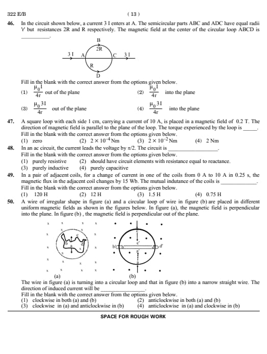
In the circuit shown below, a current 3I enters at A. The semicircular parts ABC and ADC have equal radii r but resistances 2R and R, respectively. The magnetic field at the center of the circular loop ABCD is:
![[Insert Circuit Diagram]](https://assets.collegedunia.com/public/image/10_275882e15933300b54edcc7be322b421.png?tr=w-251,h-137,c-force)
View Solution
Solution:
1. Current Distribution: The current splits inversely proportional to the resistances of the two paths:
IABC = R⁄3R * 3I = I, IADC = 2R⁄3R * 3I = 2I.
2. Magnetic Field Contribution: For a semicircular current-carrying wire, the magnetic field at the center is:
B= μ0I⁄4r
-The semicircle ABC contributes a field BABC = μ0IABC⁄4r = μ0I⁄4r.
- The semicircle ADC contributes a field BADC= μ0IADC⁄4r = μ0(2I)⁄4r = μ0I⁄2r .
3. Net Magnetic Field: The magnetic fields due to both semicircles add vectorially. Since the current flows in opposite directions in the two semicircles, their contributions will oppose. Hence,
Bnet = |BABC - BADC| = | μ0I⁄4r - μ02I⁄4r|
Bnet = μ0I⁄4r
4. Direction: Using the right-hand rule for both semicircles, the net magnetic field is out of the plane, since BADC is greater.
Conclusion: The net magnetic field = μ0I⁄4r out of the plane.
Quick Tip: For semicircular loops, calculate the magnetic field contribution for each section and apply the right-hand rule for direction.
Question 47:
A square loop with each side 1 cm, carrying a current of 10 A, is placed in a magnetic field of 0.2 T. The direction of the magnetic field is parallel to the plane of the loop. The torque experienced by the loop is:
View Solution
Solution: The torque experienced by a current loop in a magnetic field is given by:
τ = NIAB sin θ,
where:
- N = 1 (number of turns)
- I = 10 A (current in the loop)
- A = l2 = (0.01)2 = 10-4 m2 (area of the square loop)
- B = 0.2 T (magnetic field)
- θ = 90° (angle between the field and the normal to the plane of the loop, since the field is parallel to the plane, the normal to the loop makes 90° with the field).
τ = 1 * 10 * 10-4 * 0.2 * sin 90°.
τ = 2 x 10⁻⁴ Nm
Conclusion: The torque experienced by the square loop in the given configuration is 2 x 10⁻⁴ Nm.
Quick Tip: Torque on a current loop is maximized when the magnetic field is perpendicular to the plane and zero when parallel to the loop's normal.
Question 48:
In an AC circuit, the current leads the voltage by π/2. The circuit is:
View Solution
Solution: In a purely capacitive circuit, current leads the voltage by 90° or π/2. This is a characteristic phase difference.
Final Conclusion: Phase difference of π/2 indicates purely capacitive behavior.
Quick Tip: For inductors, current lags voltage; for capacitors, current leads voltage.
Question 49:
In a pair of adjacent coils, for a change of current in one coil from 0 A to 10 A in 0.25 s, the magnetic flux in the adjacent coil changes by 15 Wb. The mutual inductance of the coils is:
View Solution
Solution: Mutual inductance is given by:
M = ΔΦ⁄ΔI
Here, ΔΦ = 15 Wb, ΔI = 10 A, so:
M= 15⁄10 = 1.5H
Final Conclusion: Mutual inductance relates flux change to current change.
Quick Tip: Mutual inductance depends on flux linkage and current change. Always check units.
Question 50:
A wire of irregular shape (figure a) and a circular loop of wire (figure b) are placed in different uniform magnetic fields. In figure (a), the magnetic field is perpendicular into the plane. In figure (b), the magnetic field is perpendicular out of the plane. The wire in figure (a) is turning into a circular loop, and that in figure (b) into a narrow straight wire. The direction of induced current will be:
![[Insert Figures (a) and (b)]](https://assets.collegedunia.com/public/image/1_e6dc6545ee5f0064b12ae96b028eb046.png?tr=w-353,h-174,c-force)
View Solution
Solution:
Figure (a):
- The wire transforms into a circular loop, increasing the area.
- The magnetic field is into the plane.
- As the area increases, the magnetic flux through the loop also increases.
- To oppose this increase, the induced current flows in an anticlockwise direction, generating a magnetic field out of the plane.
- The wire transforms into a narrow straight shape, reducing the area.
- The magnetic field is out of the plane.
- As the area decreases, the magnetic flux through the loop decreases.
- To oppose this decrease, the induced current flows in an anticlockwise direction, generating a magnetic field out of the plane.
Quick Tip: Apply Lenz's Law systematically to analyze changes in flux and the direction of induced current.
*The article might have information for the previous academic years, please refer the official website of the exam.