
CBSE Class 12 2024 Physics Question Paper PDF -check Solutions with Answer key pdf (Set 1 - 65/1/1)


Content Writer | Updated On - Feb 15, 2025
CBSE 2024 Physics Question Paper (Set 1 - 55/1/1) with Solution PDF is available for download. The Central Board of Secondary Education (CBSE) conducted the exam successfully on March 4, 2024, from 10:30 AM to 1:30 PM in pen-paper mode. According to students' initial feedback, CBSE 2024 Physics Question Paper was reported as moderate. The theoretical questions were well balanced with practical-based and conceptual questions. The paper was found to be challenging in the areas of derivations and calculations, while other sections were easier to attempt
CBSE 2024 Physics Question Paper with Answer Key PDF (Set 1 - 55/1/1)
Candidate can download the CBSE 2024 Physics Question paper with Answer key PDFs for Set 1 - (55/1/1) using the link below .
| CBSE 2024 Physics Question Paper with Answer Key PDF (Set 1 - 55/1/1) |  Download Download |
Check Solution |
CBSE Class 12 Physics Question Paper With Solutions (Set 1 - 55/1/1)
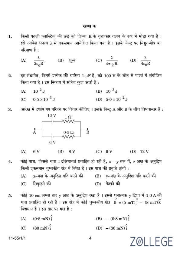
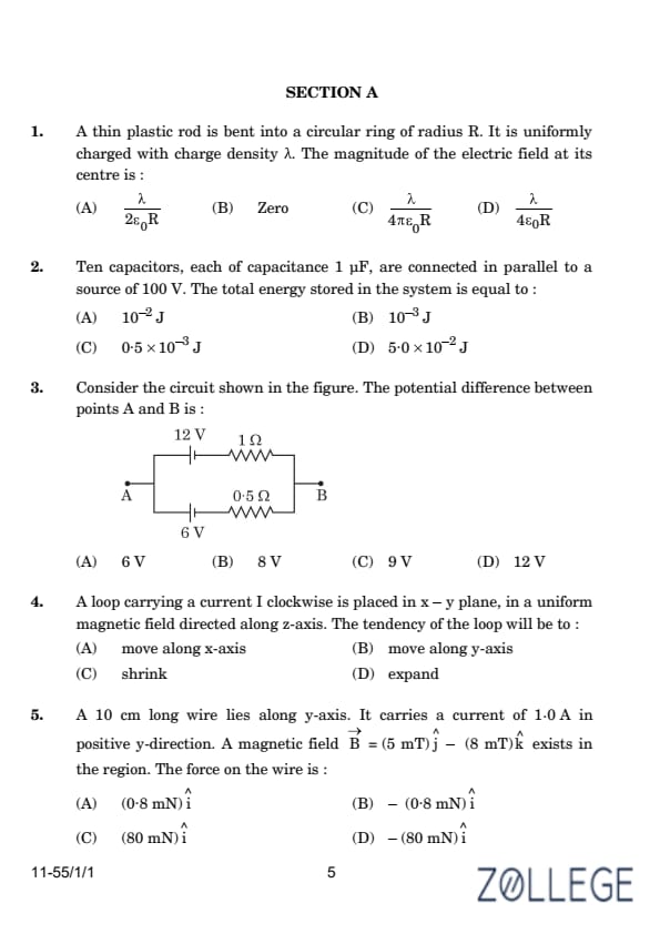
A thin plastic rod is bent into a circular ring of radius R. It is uniformly charged with charge density λ. The magnitude of the electric field at its centre is:
View Solution
The electric field at the center of a uniformly charged circular ring is zero. This is because the contributions to the electric field from all elements of the ring cancel out due to symmetry.
The electric field due to a small charge element dq on the ring at the center is:
dE = (k dq) / R², where k = 1 / (4 π ε₀). However, the vector components of the electric field from opposite elements of the ring cancel out due to symmetry, resulting in a net electric field of:
0.
Ten capacitors, each of capacitance 1 μF, are connected in parallel to a source of 100 V. The total energy stored in the system is equal to:
View Solution
The energy stored in a single capacitor is given by the formula:
E = (1 / 2) C V²
Where:
- E is the energy stored,
- C is the capacitance,
- V is the voltage across the capacitor.
For one capacitor, with C = 1 μF = 1 × 10⁻⁶ F and V = 100 V:
E₁ = (1 / 2) (1 × 10⁻⁶) (100)² = (1 / 2) × 10-6 × 104 = 5 × 10⁻² J
Since the capacitors are connected in parallel, the total energy stored in the system is the sum of the energies of all the capacitors. There are 10 capacitors, so the total energy is:
Etotal = 10 × 5 × 10-2 = 5.0 × 10⁻² J
Thus, the correct answer is:
(D) 5.0 × 10⁻² J.
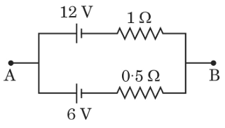
Consider the circuit shown in the figure. The potential difference between points A and B is:
View Solution
We will apply Kirchhoff’s Voltage Law (KVL) to find the potential difference between points A and B. According to KVL, the sum of the potential differences around any closed loop must be zero.
The resistors and voltage sources are arranged as follows:
- There is a 12 V source and a 1 Ω resistor in series.
- A 0.5 Ω resistor is in series with a 6 V source.
First, calculate the current flowing through the circuit. The total resistance in the circuit is:
Rtotal = 1 Ω + 0.5 Ω = 1.5 Ω
Now, calculate the total voltage in the circuit:
Vtotal = 12 V - 6 V = 6 V
Using Ohm's Law, the current I flowing through the circuit is:
I = Vtotal / Rtotal = 6 / 1.5 = 4 A
Now, calculate the potential drop across the 0.5 Ω resistor:
Vdrop = I × 0.5 = 4 × 0.5 = 2 V
Thus, the potential difference between points A and B is:
Potential difference = 6 V + 2 V = 8 V
Thus, the correct answer is:
(B) 8 V.
A loop carrying a current I clockwise is placed in the x-y plane, in a uniform magnetic field directed along the z-axis. The tendency of the loop will be to:
View Solution
The magnetic field exerts a force on each segment of the current-carrying loop. Due to the interaction between the magnetic field and the current, the magnetic forces tend to pull the loop inward, reducing its area. This tendency to shrink can be explained by the Lorentz force acting on the current elements, which generates a net torque compressing the loop.
Thus, the loop tends to shrink.
A 10 cm long wire lies along the y-axis. It carries a current of 1.0 A in the positive y-direction. A magnetic field B = (5 mT) j - (8 mT) k exists in the region. The force on the wire is:
View Solution
The magnetic force F on a current-carrying wire is given by:
F = I (L × B),
where:
- I = 1.0 A is the current,
- L = (10 cm) j = (0.1 m) j is the length vector of the wire,
- B = (5 mT) j - (8 mT) k = (5 × 10⁻³) j - (8 × 10⁻³) k is the magnetic field.
Step 1: Compute L × B:
L × B =
[determinant calculation for L × B]
Thus, L × B = -(0.8 × 10⁻³) i.
Step 2: Calculate F:
F = I (L × B) = 1.0 × -(0.8 × 10⁻³) i = -(0.8 mN) i.
Thus, the force on the wire is:
-(0.8 mN) i.
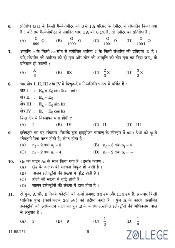
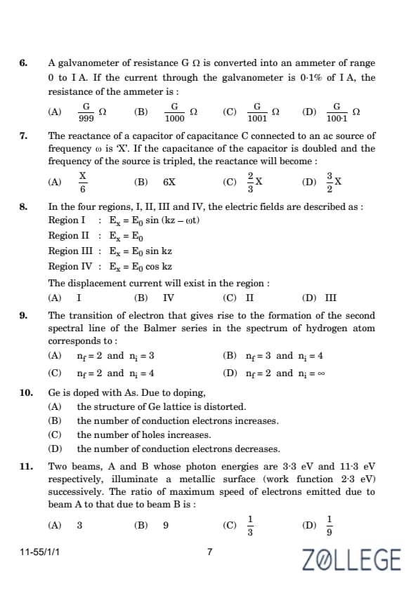
A galvanometer of resistance G Ω is converted into an ammeter of range 0 to 1 A. If the current through the galvanometer is 0.1% of 1 A, the resistance of the ammeter is:
View Solution
To convert a galvanometer into an ammeter, a shunt resistance S is connected in parallel with the galvanometer. The current through the galvanometer is given as Ig = 0.001 A (0.1% of 1 A). The total current through the ammeter is I = 1 A.
The current through the shunt is:
Is = I - Ig = 1 - 0.001 = 0.999 A.
The potential difference across the galvanometer and the shunt is the same:
Ig G = Is S.
Substitute Is and rearrange for S:
S = (Ig G) / Is = (0.001) G / 0.999.
S = G / 999.
The total resistance of the ammeter is the parallel combination of G and S:
Rammeter = G S / (G + S).
Substitute S = G / 999:
Rammeter = G (G / 999) / (G + G / 999) = G2 / (999G + G) = G / 1000.
Thus, the resistance of the ammeter is:
G / 1000 Ω.
The reactance of a capacitor of capacitance C connected to an AC source of frequency ω is X. If the capacitance of the capacitor is doubled and the frequency of the source is tripled, the reactance will become:
View Solution
The capacitive reactance XC is given by:
XC = 1 / (ω C),
where ω is the angular frequency, and C is the capacitance.
Initially, the reactance is:
X = 1 / (ω C).
When the capacitance is doubled (C' = 2C) and the frequency is tripled (ω' = 3ω), the new reactance becomes:
XC' = 1 / (ω' C') = 1 / (3ω * 2C) = 1 / (6 ω C).
Compare with the initial reactance:
XC' = X / 6.
Thus, the new reactance is:
X / 6.
In the four regions, I, II, III, and IV, the electric fields are described as:
Region I: Ex = E0 sin(kz - ωt)
Region II: Ex = E0
Region III: Ex = E0 sin(kz)
Region IV: Ex = E0 cos(kz)
The displacement current will exist in the region:
View Solution
Displacement current exists in regions where there is a time-varying electric field. In Region I, the electric field is:
Ex = E0 sin(kz - ωt).
This electric field varies with time due to the presence of the term -ωt. The displacement current density Jd is given by:
Jd = ε0 (∂Ex / ∂t).
Differentiating Ex with respect to time:
∂Ex / ∂t = -ω E0 cos(kz - ωt).
Thus, a displacement current exists in Region I. In the other regions (II, III, IV), the electric field does not vary with time, so there is no displacement current.
Therefore, the displacement current exists in:
Region I.
The transition of electron that gives rise to the formation of the second spectral line of the Balmer series in the spectrum of hydrogen atom corresponds to:
View Solution
The Balmer series corresponds to transitions where the final energy level is nf = 2. The second spectral line occurs when the transition happens from ni = 4 to nf = 2.
Using the formula for the wavelength of emitted radiation:
1 / λ = RH (1 / nf2 - 1 / ni2),
where:
- RH is the Rydberg constant,
- nf = 2 and ni = 4 for the second spectral line.
Substitute nf = 2 and ni = 4 into the equation:
1 / λ = RH (1 / 22 - 1 / 42) = RH (1 / 4 - 1 / 16).
Simplify:
1 / λ = RH * 3 / 16.
Thus, the correct transition for the second line in the Balmer series is:
nf = 2 and ni = 4.
Ge is doped with As. Due to doping:
View Solution
When germanium (Ge), a group-IV element, is doped with arsenic (As), a group-V element, it creates an n-type semiconductor. Arsenic contributes extra electrons (conduction electrons) to the material because it has five valence electrons compared to four in germanium. These extra electrons become free to conduct electricity, thus increasing the number of conduction electrons.
Thus, the effect of doping Ge with As is:
the number of conduction electrons increases.
Two beams, A and B whose photon energies are 3.3 eV and 11.3 eV respectively, illuminate a metallic surface (work function 2.3 eV) successively. The ratio of maximum speed of electrons emitted due to beam A to that due to beam B is:
View Solution
The maximum kinetic energy of emitted electrons is given by Einstein’s photoelectric equation:
Kmax = hν - φ,
where:
- hν is the photon energy,
- φ is the work function of the metal.
For beam A:
Kmax,A = 3.3 - 2.3 = 1.0 eV.
For beam B:
Kmax,B = 11.3 - 2.3 = 9.0 eV.
The maximum speed of the emitted electrons is related to the kinetic energy by:
Kmax = (1/2) m vmax2.
Thus:
vmax = √(2 Kmax / m).
The ratio of speeds is:
vmax,A / vmax,B = √(Kmax,A / Kmax,B).
Substitute the values:
vmax,A / vmax,B = √(1.0 / 9.0) = 1/3.
Thus, the ratio of maximum speeds is:
1/3.
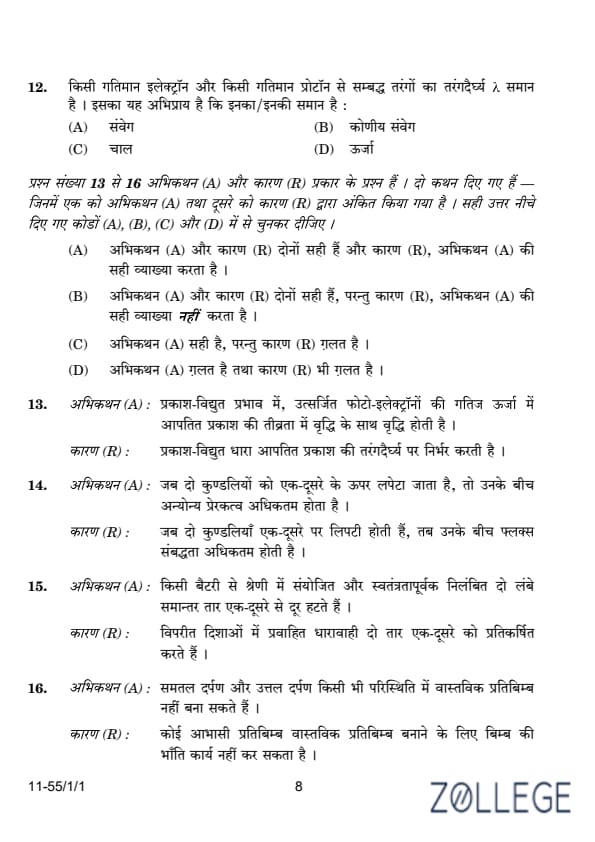
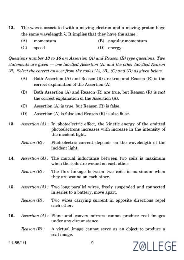
The waves associated with a moving electron and a moving proton have the same wavelength λ. It implies that they have the same:
View Solution
The de Broglie wavelength λ of a particle is given by:
λ = h / p,
where:
- h is Planck's constant,
- p is the momentum of the particle.
If two particles have the same de Broglie wavelength, then their momenta must be the same, because λ is inversely proportional to p. However, their masses may differ, and thus their speeds and energies can be different.
For a moving electron and a moving proton, having the same wavelength implies:
pelectron = pproton.
Thus, the correct answer is:
momentum.
Assertion (A): In photoelectric effect, the kinetic energy of the emitted photoelectrons increases with increase in the intensity of the incident light.
Reason (R): Photoelectric current depends on the wavelength of the incident light.
View Solution
In the photoelectric effect, the kinetic energy of the emitted photoelectrons depends on the frequency (or wavelength) of the incident light, not its intensity. Hence, Assertion (A) is false. The photoelectric current depends on the intensity of the incident light and not its wavelength, so Reason (R) is also false.
Thus, the correct answer is:
Assertion (A) is false and Reason (R) is also false.
Assertion (A): The mutual inductance between two coils is maximum when the coils are wound on each other.
Reason (R): The flux linkage between two coils is maximum when they are wound on each other.
View Solution
Mutual inductance between two coils depends on the extent of magnetic flux linkage between them. When the coils are wound on each other, the magnetic flux linkage is maximum, and hence the mutual inductance is also maximum.
Therefore, both the Assertion (A) and the Reason (R) are true, and Reason (R) correctly explains Assertion (A).
Thus, the correct answer is:
Both Assertion (A) and Reason (R) are true and Reason (R) is the correct explanation of the Assertion (A).
Assertion (A): Two long parallel wires, freely suspended and connected in series to a battery, move apart.
Reason (R): Two wires carrying current in opposite directions repel each other.
View Solution
The assertion states that two long parallel wires, freely suspended and connected to a battery in series, move apart. This behavior is due to the magnetic forces acting on the wires. When electric current flows through the wires, they generate magnetic fields around them.
The reason states that two wires carrying current in opposite directions repel each other. This is a result of the force between two parallel currents, described by Ampère's Law. When currents flow in opposite directions in parallel wires, the magnetic fields generated by the wires exert a repulsive force on each other, causing the wires to move apart.
Thus, both the assertion and the reason are true, and the reason correctly explains the assertion.
Thus, the correct answer is:
Both Assertion (A) and Reason (R) are true and Reason (R) is the correct explanation of the Assertion (A).
Assertion (A): Plane and convex mirrors cannot produce real images under any circumstance.
Reason (R): A virtual image cannot serve as an object to produce a real image.
View Solution
The assertion (A) is false because while it is true that a plane mirror cannot produce a real image, a convex mirror can produce virtual images but does not produce real images under any circumstance. Thus, the assertion is incorrect.
The reason (R) is also false. A virtual image formed by one mirror can indeed serve as an object for another mirror, and a real image can be formed by using this object. Thus, the statement that a virtual image cannot serve as an object for producing a real image is also incorrect.
Therefore, the correct answer is:
Assertion (A) is false and Reason (R) is also false.
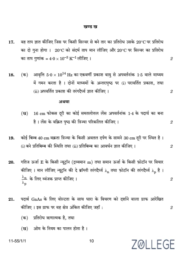
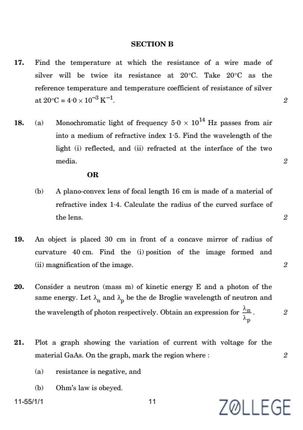
Find the temperature at which the resistance of a wire made of silver will be twice its resistance at 20°C. Take 20°C as the reference temperature and the temperature coefficient of resistance of silver at 20°C as 4.0 × 10⁻³ K-1.
View Solution
The resistance of a material varies with temperature according to the formula:
RT = R0 (1 + α ΔT),
where:
- RT is the resistance at temperature T,
- R0 is the resistance at the reference temperature T0,
- α is the temperature coefficient of resistance,
- ΔT = T - T0 is the temperature difference.
Given that RT = 2R0, α = 4.0 × 10⁻³ K-1, and T0 = 20°C, substitute these values:
2R0 = R0 (1 + α ΔT).
Cancel R0 on both sides:
2 = 1 + α ΔT.
Rearrange to find ΔT:
ΔT = (2 - 1) / α = 1 / (4.0 × 10⁻³) = 250 K.
Calculate the temperature T:
T = T0 + ΔT = 20 + 250 = 270°C.
Thus, the temperature at which the resistance of the wire is twice its resistance at 20°C is:
270°C.
Monochromatic light of frequency 5.0 × 10¹⁴ Hz passes from air into a medium of refractive index 1.5. Find the wavelength of the light (i) reflected, and (ii) refracted at the interface of the two media.
View Solution
The wavelength λ of light is related to its speed and frequency by:
λ = v / f.
For light in air:
vair = c = 3.0 × 10⁸ m/s.
The wavelength in air is:
λair = vair / f = (3.0 × 10⁸) / (5.0 × 10¹⁴) = 600 nm.
(i) The wavelength of the reflected light remains the same as in air:
λreflected = 600 nm.
(ii) For refracted light in the medium:
vmedium = vair / n = (3.0 × 10⁸) / 1.5 = 2.0 × 10⁸ m/s.
The wavelength in the medium is:
λrefracted = vmedium / f = (2.0 × 10⁸) / (5.0 × 10¹⁴) = 400 nm.
Thus:
λrefracted = 400 nm.
A plano-convex lens of focal length 16 cm is made of a material of refractive index 1.4. Calculate the radius of the curved surface of the lens.
View Solution
The lens formula is given by:
1 / f = (μ - 1) (1 / R1 - 1 / R2).
For the given lens with a refractive index μ = 1.4, and the relation becomes:
1 / 16 = (1.4 - 1) (1 / R).
Since 1 / ∞ = 0, the equation simplifies to:
1 / 16 = 0.4 × 1 / R.
Solving for R:
R = 16 × 0.4 = 6.4 cm.
Thus, the radius of the curved surface is:
R = 6.4 cm.
An object is placed 30 cm in front of a concave mirror of radius of curvature 40 cm. Find the (i) position of the image formed and (ii) magnification of the image.
View Solution
(i) The lens formula is given by:
1 / v + 1 / u = 1 / f
Substituting the given values:
1 / v + 1 / -30 = 1 / -20
Now, solving for v:
1 / v = 1 / -20 - 1 / -30
1 / v = (-3 + 2) / 60 = -1 / 60
v = -60 cm
Thus, the value of v is -60 cm.
(ii) The magnification (m) is given by:
m = - v / u
Substituting the values of v = -60 cm and u = -30 cm:
m = - (-60 / -30) = -2
Thus, the magnification is m = -2.
Consider a neutron (mass m) of kinetic energy E and a photon of the same energy. Let λn and λp be the de Broglie wavelength of the neutron and the wavelength of the photon, respectively. Obtain an expression for λn / λp.
View Solution
We are given the equation for energy E:
E = hc / λp ⇒ λp = hc / E
Now, using the relation λn = h / p, where p is the momentum, we can substitute the expression for p:
λn = h / √(2mE)
Now, substituting the expression for p:
λn / λp = (h / √(2mE)) / (hc / Ehc) = E / √(2mc2)
Thus, we get the expression:
λn / λp = √(E / 2mc2)
This gives us the desired expression for λn / λp.
Plot a graph showing the variation of current with voltage for the material GaAs. On the graph, mark the region where:
(a) resistance is negative, and
(b) Ohm’s law is obeyed.
View Solution
Gallium arsenide (GaAs) exhibits negative resistance in certain regions of its current-voltage (I-V) characteristic curve. The graph typically shows a linear region (Ohm’s law), followed by a region of negative slope (negative resistance), and then a saturation region.
The regions can be identified as follows:
- (a) The region where resistance is negative corresponds to the portion of the I-V curve with a negative slope (decreasing current with increasing voltage).
- (b) The region where Ohm’s law is obeyed corresponds to the initial linear part of the I-V curve.
A qualitative sketch of the I-V graph is shown below:
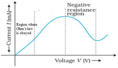
The graph marks the linear region for Ohm’s law and the negative resistance region.
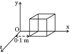
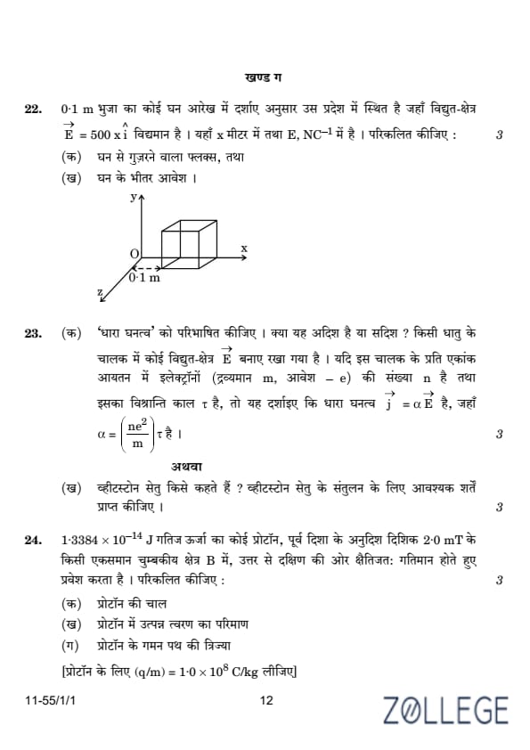
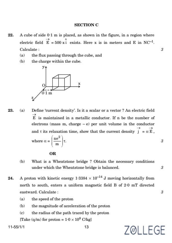
A cube of side 0.1 m is placed, as shown in the figure, in a region where electric field E = 500x î exists. Here x is in meters and E in N/C. Calculate:
(a) the flux passing through the cube, and
(b) the charge within the cube.
View Solution
The electric flux Φ through a surface is given by:
Φ = ∫ E ⋅ dA,
where:
- E is the electric field,
- dA is the area vector perpendicular to the surface.
(a) The flux through the cube:
The electric field varies as E = 500x î. Only the two faces of the cube perpendicular to the x-axis contribute to the flux. Let the cube extend from x = 0 to x = 0.1 m.
At x = 0: The electric field is:
E = 500 × 0 = 0 N/C.
At x = 0.1 m: The electric field is:
E = 500 × 0.1 = 50 N/C.
The area of each face of the cube is:
A = (0.1)2 = 0.01 m².
The flux through the face at x = 0 is:
Φ₁ = E ⋅ A = 0 × 0.01 = 0 Nm²/C.
The flux through the face at x = 0.1 m is:
Φ₂ = E ⋅ A = 50 × 0.01 = 0.5 Nm²/C.
The net flux through the cube is:
Φ = Φ₂ - Φ₁ = 0.5 - 0 = 0.5 Nm²/C.
Thus, the flux passing through the cube is:
Φ = 0.5 Nm²/C.
(b) The charge within the cube:
Using Gauss's law:
Φ = qenclosed / ε₀,
where ε₀ = 8.854 × 10⁻¹² C²/Nm² is the permittivity of free space.
Rearrange to find qenclosed:
qenclosed = Φ × ε₀.
Substitute the values:
qenclosed = 0.5 × 8.854 × 10-12 = 4.427 × 10⁻¹² C.
Thus, the charge within the cube is:
qenclosed = 4.43 × 10⁻¹² C.
Define ‘current density’. Is it a scalar or a vector? An electric field E is maintained in a metallic conductor. If n be the number of electrons (mass m, charge -e) per unit volume in the conductor and τ its relaxation time, show that the current density j = α E, where α = (ne² / m) τ.
View Solution
Definition of Current Density:
The current density j is defined as the current per unit cross-sectional area. Mathematically:
j = I / A,
where I is the current and A is the cross-sectional area. Current density is a vector quantity because it has both magnitude and direction.
Derivation:
The current I through a conductor is given by:
I = nqA vd,
where:
- n is the number of charge carriers per unit volume,
- q is the charge of each carrier,
- A is the cross-sectional area,
- vd is the drift velocity of the charge carriers.
Substitute vd using vd = μE, where μ is the mobility of charge carriers and E is the electric field:
I = nqA (μ E).
The current density j is:
j = I / A = nq (μ E).
Using μ = eτ / m, where τ is the relaxation time and m is the mass of the charge carriers, substitute μ:
j = nq (eτ / m) E.
Simplify:
j = (ne² τ / m) E.
Thus, α = ne² τ / m, and:
j = α E.
What is a Wheatstone bridge? Obtain the necessary conditions under which the Wheatstone bridge is balanced.
View Solution
Definition of Wheatstone Bridge:
A Wheatstone bridge is a circuit used to measure unknown resistances. It consists of four resistors arranged in a diamond shape, with a galvanometer connected between two opposite nodes.
Condition for Balance:
Let the resistances of the four arms of the Wheatstone bridge be R₁, R₂, R₃, and R₄. The bridge is balanced when no current flows through the galvanometer. This occurs when:
R₁ / R₂ = R₃ / R₄.
Derivation:
At balance, the potentials at the two points connected to the galvanometer are equal. Using Ohm's law:
VAB / R₁ = VAD / R₂, and VAB / R₃ = VAD / R₄.
Simplify:
R₁ / R₂ = R₃ / R₄.
Thus, the condition for the Wheatstone bridge to be balanced is:
R₁ / R₂ = R₃ / R₄.
A proton with kinetic energy 1.3384 × 10⁻¹⁴ J moving horizontally from north to south, enters a uniform magnetic field B = 2.0 mT directed eastward. Calculate:
(a) the speed of the proton,
(b) the magnitude of acceleration of the proton,
(c) the radius of the path traced by the proton.
[Take q/m for proton = 1.0 × 10⁸ C/kg].
View Solution
a) The velocity v is given by the equation:
v = √(2 × K.E. / m)
Substituting the values:
v = 4 × 10⁶ m/s
b) The acceleration a is given by the equation:
a = qvB / m
Substituting the values:
a = 8 × 10¹¹ m/s²
c) The radius r of the path is given by:
r = mv / Bq
Substituting the values:
r = 20 m
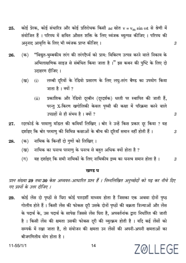
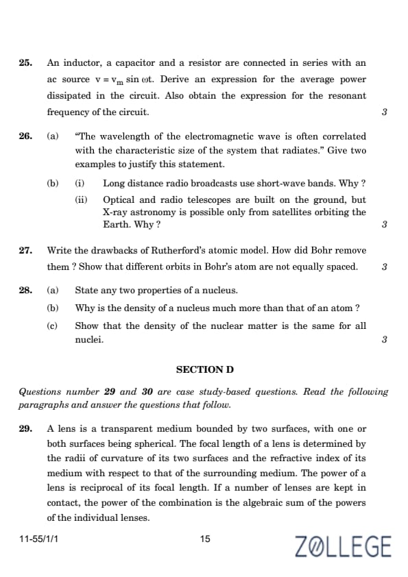
An inductor, a capacitor, and a resistor are connected in series with an AC source \( v = v_m \sin \omega t \). Derive an expression for the average power dissipated in the circuit. Also, obtain the expression for the resonant frequency of the circuit.
View Solution
Deriving an expression for the average power dissipated in a series LCR circuit:
The voltage is given by:
v = v_m sin(ωt)
The current is:
i = i_m sin(ωt + φ)
The power P is given by the product of voltage and current:
P = v × i = (v_m sin(ωt)) × (i_m sin(ωt + φ))
This simplifies to:
P = (v_m i_m / 2) [cos φ - cos(2ωt + φ)]
The average power over a cycle is given by averaging the two terms on the right-hand side of the above expression. The second term is time-dependent, while the first term is constant. Therefore, the average power P is:
P = (v_m i_m / 2) cos φ
Obtaining the expression for the resonant frequency:
At resonance, the reactance of the capacitor X_C equals the reactance of the inductor X_L:
1 / (ωC) = ωL
This gives the angular frequency ω as:
ω = 1 / √(LC)
Thus, the resonant frequency f is:
f = 1 / (2π√(LC))
"The wavelength of the electromagnetic wave is often correlated with the characteristic size of the system that radiates." Give two examples to justify this statement.
View Solution
1. Radio Waves: Large antenna arrays are used for radio wave transmission because the wavelength of radio waves is in meters, requiring similarly sized systems to efficiently radiate or receive these waves.
2. Microwaves: Microwaves have a wavelength on the order of centimeters, which matches the size of cavities or waveguides used for their propagation in microwave ovens or radar systems.
(i) Why do long-distance radio broadcasts use short-wave bands?
(ii) Why are optical and radio telescopes built on the ground, but X-ray astronomy is possible only from satellites orbiting the Earth?
View Solution
(i) Long-distance radio broadcasts use short-wave bands because these bands undergo ionospheric reflection, allowing them to travel large distances beyond the line of sight.
(ii) Optical and radio telescopes can be built on the ground because these waves can penetrate the Earth's atmosphere. X-rays, however, are absorbed by the atmosphere, making it necessary to place X-ray telescopes on satellites.
Write the drawbacks of Rutherford’s atomic model. How did Bohr remove them? Show that different orbits in Bohr’s atom are not equally spaced.
View Solution
Drawbacks of Rutherford’s atomic model:
(i) According to classical electromagnetic theory, an accelerating charged particle emits radiation in the form of electromagnetic waves. The energy of an accelerating electron should therefore continuously decrease, causing the electron to spiral inward and eventually fall into the nucleus. As a result, such an atom cannot be stable.
(ii) As the electrons spiral inward, their angular velocities and hence their frequencies would change continuously. This would lead to the emission of a continuous spectrum, which contradicts the line spectrum that is actually observed.
Bohr's explanation:
Bohr postulated stable orbits in which electrons do not radiate energy. The postulates are as follows:
- An electron in an atom can revolve in certain stable orbits without the emission of radiant energy.
- The electron revolves around the nucleus in only those orbits for which the angular momentum is an integral multiple of \(\frac{h}{2\pi}\).
- An electron might make a transition from one of its specified non-radiating orbits to another of lower energy. When this happens, a photon is emitted with energy equal to the difference in energy between the initial and final states.
The radius of the \(n^{th}\) orbit is given by:
rₙ = n²h² / 4π²me² or rₙ ∝ n²
Alternatively:
The difference in the radius of consecutive orbits is:
rₙ₊₁ - rₙ = k[(n+1)² - n²]
This simplifies to:
rₙ₊₁ - rₙ = k(2n + 1)
which depends on \(n\), meaning it is not a constant.
(a) State any two properties of a nucleus.
(b) Why is the density of a nucleus much more than that of an atom?
(c) Show that the density of nuclear matter is the same for all nuclei.
View Solution
(a) Properties of a Nucleus:
1. The nucleus contains protons and neutrons, collectively called nucleons.
2. The nucleus has a positive charge due to the presence of protons.
(b) Nuclear Density:
The nucleus is much denser than the atom because most of the mass of an atom is concentrated in its tiny nucleus, whereas the atom's size includes the much larger electron cloud.
(c) Density of Nuclear Matter:
The volume of a nucleus is proportional to \(A\), where \(A\) is the mass number. The radius \(R\) of a nucleus is given by:
R = R₀ A1/3
The density of the nucleus is:
ρ = Mass of Nucleus / Volume of Nucleus = mₙ A / (4/3 π R3) = mₙ / (4/3 π R₀3)
Since R₀ and mₙ are constants, the density is the same for all nuclei.
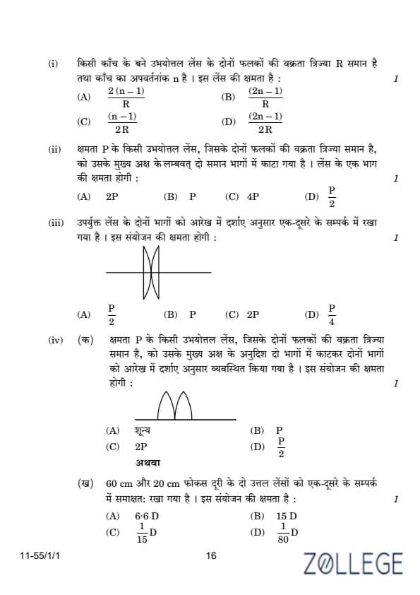
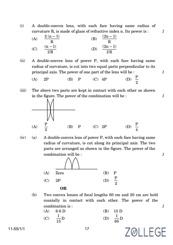
A lens is a transparent medium bounded by two surfaces, with one or both surfaces being spherical. The focal length of a lens is determined by the radii of curvature of its two surfaces and the refractive index of its medium with respect to that of the surrounding medium. The power of a lens is reciprocal of its focal length. If a number of lenses are kept in contact, the power of the combination is the algebraic sum of the powers of the individual lenses.
(A) (2(n-1))/R
(B) (2n-1)/R
(C) (n-1)/2R
(D) (2n-1)/2R
Correct Answer: (A) (2(n-1))/R
View Solution
The lens maker’s formula is given by: 1/f = (n-1) ((1/R1) - (1/R2)).
For a double-convex lens, both surfaces have the same radius of curvature R, and: 1/f = (n-1) ((1/R) - (-1/R)).
1/f = (n-1) * 2/R.
The power P of the lens is: P = 1/f = (2(n-1))/R.
A double-convex lens of power P, with each face having the same radius of curvature, is cut into two equal parts perpendicular to its principal axis. The power of one part of the lens will be:
(A) 2P
(B) P
(C) 4P
(D) P/2
Correct Answer: (D) P/2
View Solution
When a lens is cut into two equal parts perpendicular to its principal axis, the curvature of each part remains the same as the original lens. However, the effective thickness of each part is halved. The power of a lens is inversely proportional to its focal length, and the focal length is proportional to the thickness of the lens.
Since the thickness is halved, the focal length of one part will also be halved. This results in the power of one part being twice that of the original lens. Therefore, the power of one part of the lens will be: P/2.
Thus, the correct answer is: P/2.
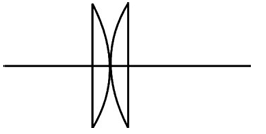
The above two parts are kept in contact with each other as shown in the figure. The power of the combination will be:
(A) P/2
(B) P
(C) 2P
(D) P/4
Correct Answer: (C) 2P
View Solution
When two lenses are kept in contact, the total power of the combination is the algebraic sum of their individual powers. Since both parts have power P, the total power is:
Ptotal = P + P = 2P.
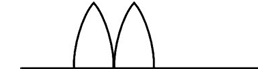
A double-convex lens of power P, with each face having the same radius of curvature, is cut along its principal axis. The two parts are arranged as shown in the figure. The power of the combination will be:
(A) Zero
(B) P
(C) 2P
(D) P/2
Correct Answer: (C) 2P
View Solution
When a double-convex lens is cut along its principal axis, the resulting two parts will each behave as a plano-convex lens. The focal length of each part will be halved, and the power is inversely proportional to the focal length. Since the focal length of each part is halved, the power of each part will be doubled.
When these two parts are combined, their powers will add up. Therefore, the total power of the combination will be:
Ptotal = P + P = 2P
Thus, the power of the combination is 2P.
Two convex lenses of focal lengths 60 cm and 20 cm are held coaxially in contact with each other. The power of the combination is:
(A) 6.6 D
(B) 15 D
(C) 1/15 D
(D) 1/80 D
Correct Answer: (A) 6.6 D
View Solution
The power P of a lens is given by the equation:
P = 1/f
Where f is the focal length of the lens in meters. The power of two lenses in contact is the sum of their individual powers:
Ptotal = P1 + P2
For the first lens with a focal length of 60 cm (or 0.6 m):
P1 = 1/0.6 = 1.67 D
For the second lens with a focal length of 20 cm (or 0.2 m):
P2 = 1/0.2 = 5 D
The total power of the combination is:
Ptotal = 1.67 D + 5 D = 6.67 D
Thus, the correct answer is approximately 6.6 D.
Thus, the correct answer is 6.6 D.
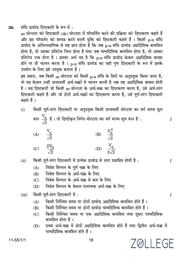
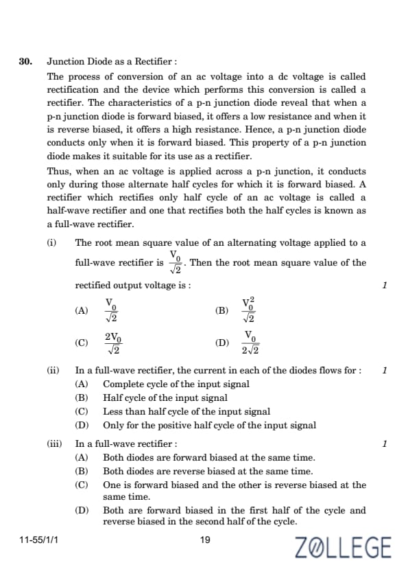
Junction Diode as a Rectifier:
The process of conversion of an ac voltage into a dc voltage is called rectification and the device which performs this conversion is called a rectifier. The characteristics of a p-n junction diode reveal that when a p-n junction diode is forward biased, it offers a low resistance and when it is reverse biased, it offers a high resistance. Hence, a p-n junction diode conducts only when it is forward biased. This property of a p-n junction diode makes it suitable for its use as a rectifier.
Thus, when an ac voltage is applied across a p-n junction, it conducts only during those alternate half cycles for which it is forward biased. A rectifier which rectifies only half cycle of an ac voltage is called a half-wave rectifier and one that rectifies both the half cycles is known as a full-wave rectifier.
The root mean square (RMS) value of an alternating voltage applied to a full-wave rectifier is V0/√2. Then the root mean square value of the rectified output voltage is:
(A) V0/√2
(B) V02/√2
(C) 2V0/√2
(D) V0/2√2
Correct Answer: (A) V0/√2
View Solution
For a full-wave rectifier, the rectified output voltage waveform consists of the absolute values of the input AC voltage waveform. The RMS value of the output voltage is calculated as:
Vrms = √(1/T ∫0T Vrectified2 dt)
Since the full-wave rectifier converts both halves of the alternating current waveform into positive polarity, the RMS value remains the same as that of the input AC voltage waveform:
Vrms = V0/√2
Thus, the RMS value of the rectified output voltage is V0/√2.
In a full-wave rectifier, the current in each of the diodes flows for:
(A) Complete cycle of the input signal
(B) Half cycle of the input signal
(C) Less than half cycle of the input signal
(D) Only for the positive half cycle of the input signal
Correct Answer: (B) Half cycle of the input signal
View Solution
In a full-wave rectifier circuit, there are two diodes that conduct current alternately during the positive and negative half-cycles of the AC input signal. Each diode conducts for only half of the input signal cycle. The conduction process works as follows:
- During the positive half-cycle, one diode is forward biased, allowing current to flow.
- During the negative half-cycle, the other diode becomes forward biased and conducts current.
Thus, each diode conducts current for half the cycle of the input signal.
In a full-wave rectifier:
(A) Both diodes are forward biased at the same time.
(B) Both diodes are reverse biased at the same time.
(C) One is forward biased and the other is reverse biased at the same time.
(D) Both are forward biased in the first half of the cycle and reverse biased in the second half of the cycle.
Correct Answer: (C) One is forward biased and the other is reverse biased at the same time.
View Solution
In a full-wave rectifier, the two diodes are connected such that:
- During the positive half-cycle of the AC input, one diode is forward biased (allowing current to flow), while the other is reverse biased (blocking current).
- During the negative half-cycle, the roles are reversed. The previously reverse-biased diode becomes forward biased and conducts current, while the other diode becomes reverse biased and blocks current.
At any given time, one diode is conducting (forward biased), and the other diode is blocking (reverse biased).
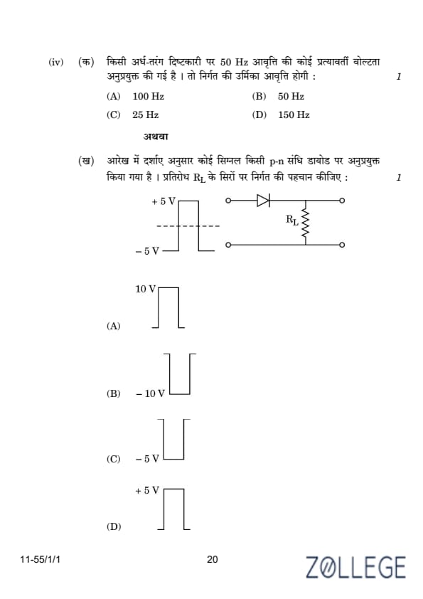
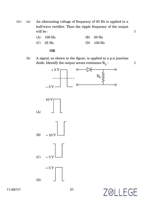
An alternating voltage of frequency 50 Hz is applied to a half-wave rectifier. Then the ripple frequency of the output will be:
(A) 100 Hz
(B) 50 Hz
(C) 25 Hz
(D) 150 Hz
Correct Answer: (B) 50 Hz
View Solution
In a half-wave rectifier, only one half of the alternating current (either positive or negative half-cycle) is used for rectification. The output waveform consists of pulses that correspond to the frequency of the input AC signal. Therefore, the frequency of the ripple in the output is the same as the input frequency:
fripple = finput = 50 Hz
Thus, the ripple frequency of the output is 50 Hz.
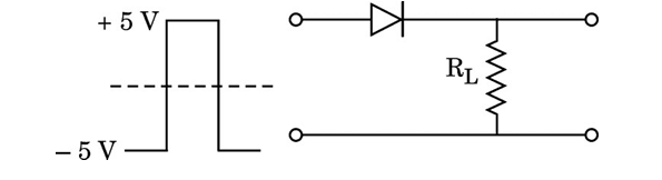
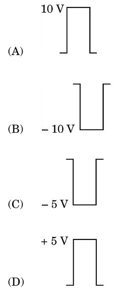
A signal, as shown in the figure, is applied to a p-n junction diode. Identify the output across the resistance RL:
Correct Answer: (D) 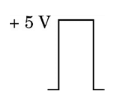

View Solution
The circuit consists of a p-n junction diode in series with a load resistor RL. The input signal alternates between +5 V and -5 V. The behavior of the diode depends on the polarity of the input signal:
- Positive Half-Cycle (+5 V): The diode is forward biased during the positive half-cycle. This allows current to flow through the load resistor RL, and the output voltage across RL is equal to the input voltage of +5 V.
- Negative Half-Cycle (-5 V): The diode is reverse biased during the negative half-cycle. In this condition, the diode does not conduct, and no current flows through RL. The output voltage across RL is zero during this phase.
The output waveform across RL consists only of the positive half-cycles of the input signal, and its amplitude is +5 V.
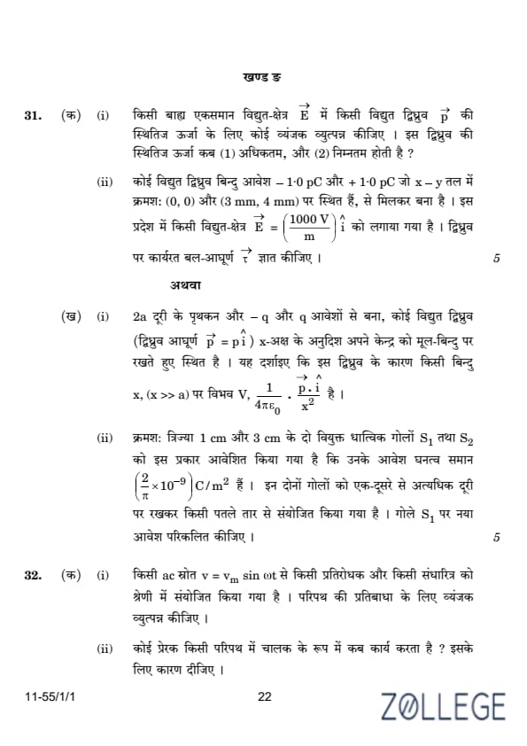
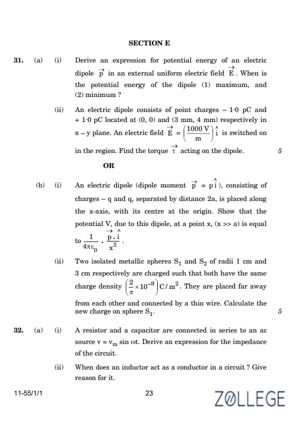
(a)(i) Derive an expression for potential energy of an electric dipole p in an external uniform electric field E. When is the potential energy of the dipole (1) maximum, and (2) minimum?
Correct Answer: Maximum potential energy: U = +pE when θ = 180°. Minimum potential energy: U = -pE when θ = 0°.
View Solution
In the figure, the dipole moment p is placed in a uniform electric field E. The potential energy is given by the equation:
U(θ) = -pE cos(θ)
The potential energy is maximum when θ = 180°, and minimum when θ = 0°.
(a)(ii) An electric dipole consists of point charges -1.0 pC and +1.0 pC located at (0, 0) and (3 mm, 4 mm) respectively in the x–y plane. An electric field E = (1000 V/m) i is switched on in the region. Find the torque τ acting on the dipole.
Correct Answer: Torque acting on the dipole: τ = 12 × 10-12 N·m.
View Solution
The torque τ is given by:
τ = pE sin(θ)
This can be written as:
τ = (2aq) E sin(θ)
Substituting the known values:
τ = (5 × 10-3 × 1 × 10-12 × 103) × 4/5
Simplifying:
τ = 4 × 10-12 Nm
The direction of the torque is along the negative Z-direction.
(b)(i) An electric dipole (dipole moment p = p i), consisting of charges -q and q, separated by distance 2a, is placed along the x-axis, with its center at the origin. Show that the potential V, due to this dipole, at a point x (x ≫ a) is equal to: V = (1 / 4πϵ0) · (p · i) / x2.
Correct Answer: Potential at x: V = (1 / 4πϵ0) · (p · i) / x2.
View Solution
The potential V due to two point charges +q and -q separated by a distance 2a can be calculated using:
V = (1 / 4πϵ0) [ q / (x - a) - q / (x + a) ]
Simplifying this, we get:
V = (q / 4πϵ0) [(x + a - x + a) / (x2 - a2)]
Thus, the potential becomes:
V = (q / 4πϵ0) · (2a / (x2 - a2)) = (p / 4πϵ0) · (1 / (x2 - a2))
where p = 2aq is the dipole moment.
Since p is along the x-axis, the potential can be written as:
V = (1 / 4πϵ0) · (p / x2)
If x ≫ a, the potential simplifies to:
V = (1 / 4πϵ0) · (p / x2)
(b)(ii) Two isolated metallic spheres S1 and S2 of radii 1 cm and 3 cm respectively are charged such that both have the same charge density σ = (2 / π) × 10-9 C/m2. They are placed far away from each other and connected by a thin wire. Calculate the new charge on sphere S1.
Correct Answer: New charge on S1: Q1 = 8.38 nC.
View Solution
Charge Redistribution Between Spheres
Charge on sphere S1:
Q1 = σ × Surface Area = (2 × 10⁻⁹ / π) × 4π (1 × 10⁻²)2 = 8 × 10-13 C
Charge on sphere S2:
Q2 = σ × Surface Area = (2 × 10⁻⁹ / π) × 4π (3 × 10⁻²)2 = 72 × 10-13 C
When the two spheres are connected by a thin wire, they acquire a common potential V, and the charge remains conserved. Therefore:
Q1 + Q2 = Q1' + Q2'
= C1 V + C2 V
Thus,
Q1 + Q2 = (C1 + C2) V
The capacitances C1 and C2 are given by:
C1 = 4π ε0 r1 = (1 / 9) × 10-11 F
C2 = 4π ε0 r2 = (1 / 3) × 10-11 F
Now, we calculate the common potential V:
V = (80 × 10-13) / ((1 / 9) × 10-11 + (1 / 3) × 10-11) = 1.8 V
Substituting into Q1' = C1 × V, we get:
Q1' = C1 × V = (1 / 9) × 10-11 × 1.8 = 2 × 10-12 C
Derive an expression for the impedance of a circuit consisting of a resistor and a capacitor connected in series to an AC source v = vm sin(ωt).
Correct Answer: Impedance of the circuit:
Z = √(R2 + 1/ω2C2).
View Solution
Derivation of Impedance:
The total voltage in a series R-C circuit is given by:
v = vR + vC,
where:
- vR = i R is the voltage across the resistor,
- vC = i / (jωC) is the voltage across the capacitor.
The current in the circuit is the same through all components, and the impedance Z of the circuit is given by:
Z = v / i.
The impedance of the resistor is purely real, ZR = R, and the impedance of the capacitor is purely imaginary, ZC = -j / (ωC). The total impedance is:
Z = ZR + ZC = R - j / (ωC).
The magnitude of the impedance is:
|Z| = √(Re(Z)2 + Im(Z)2).
Substituting the real and imaginary parts:
|Z| = √(R2 + ( -1 / ωC )2) = √(R2 + 1 / ω2C2).
Thus, the impedance of the circuit is:Z = √(R2 + 1 / ω2C2).
When does an inductor act as a conductor in a circuit? Give reason for it.
Correct Answer: An inductor acts as a conductor in a DC circuit when the current is steady (constant). This is because the induced emf is zero in the absence of a changing magnetic flux.
View Solution
Inductor Acting as a Conductor:
An inductor acts as a conductor in a DC circuit when the current is steady (i.e., not changing with time). This happens because:
ℰ = -L (dI/dt).
- The induced emf in the inductor is given by Faraday's Law:
- When the current I is steady, dI/dt = 0, and hence the induced emf is zero.
With no opposing emf, the inductor behaves as a simple conductor with negligible resistance, allowing the current to flow freely.
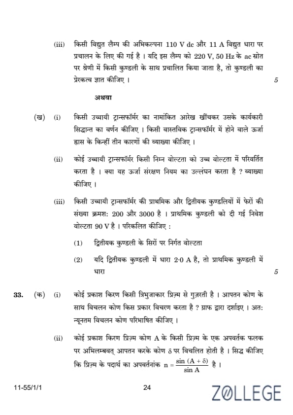
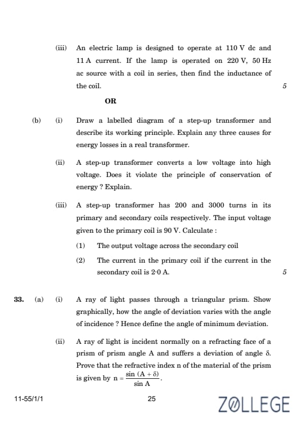
An electric lamp is designed to operate at 110 V DC and 11 A current. If the lamp is operated on 220 V, 50 Hz AC source with a coil in series, then find the inductance of the coil.
Correct Answer: The inductance of the coil is L = 0.064 H.
View Solution
The lamp is designed for DC operation with the following specifications:
VDC = 110 V, I = 11 A.
The power consumed by the lamp is:
P = VDC · I = 110 · 11 = 1210 W.
When the lamp is connected to an AC source of 220 V and 50 Hz with a coil in series, the total impedance Z of the circuit is given by:
Z = VAC / I = 220 / 11 = 20 Ω.
The impedance of the circuit is the combination of the resistance of the lamp and the inductive reactance of the coil:
Z = √(R2 + XL2).
The resistance of the lamp is:
R = VDC / I = 110 / 11 = 10 Ω.
The inductive reactance XL is given by:
XL = √(Z2 - R2).
Substituting the values:
XL = √(202 - 102) = √(400 - 100) = √300 = 10√3 Ω.
The inductive reactance is related to the inductance L by:
XL = ωL,
where ω = 2πf is the angular frequency of the AC source. For f = 50 Hz:
ω = 2π · 50 = 100π rad/s.
Substituting for L:
L = XL / ω = (10√3) / (100π).
Simplifying:
L = √3 / (10π) H.
Approximating:
L ≈ 0.064 H.
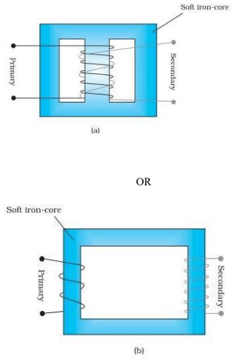
Draw a labelled diagram of a step-up transformer and describe its working principle. Explain any three causes for energy losses in a real transformer.
Correct Answer: The transformer does not violate the principle of conservation of energy.
View Solution
Step-Up Transformer:
A step-up transformer increases the voltage by having more turns in the secondary coil compared to the primary coil.
Working Principle:
A step-up transformer works on the principle of electromagnetic induction. When an alternating current flows through the primary coil, it generates a varying magnetic flux in the core. This varying flux induces an electromotive force (EMF) in the secondary coil according to Faraday's Law:
ℰ = -dΦB/dt.
The voltage ratio between the primary and secondary coils is given by the turns ratio:
Vs/Vp = Ns/Np.
Energy Losses in Transformers:
- Eddy Current Losses: Circulating currents in the core produce heat, reducing efficiency. These are minimized by using laminated cores.
- Hysteresis Losses: Energy is lost during repeated magnetization and demagnetization of the core. Soft magnetic materials help reduce this loss.
- Copper Losses: Heat is generated due to the resistance of the windings. This can be reduced by using low-resistance materials for the coils.
A step-up transformer converts a low voltage into high voltage. Does it violate the principle of conservation of energy? Explain.
View Solution
Conservation of Energy in Transformers:
A step-up transformer increases the voltage but decreases the current proportionally, ensuring that the power remains constant (ignoring losses). The relationship is given by:
Ps = Pp ⟶ Vs Is = Vp Ip.
Since the power output is equal to the power input (in an ideal transformer), the principle of conservation of energy is not violated. Any apparent violation is due to energy losses in the transformer, such as eddy current, hysteresis, and copper losses.
A step-up transformer has 200 and 3000 turns in its primary and secondary coils respectively. The input voltage given to the primary coil is 90 V. Calculate:
(1) The output voltage across the secondary coil
(2) The current in the primary coil if the current in the secondary coil is 2.0 A.
Correct Answer: (1) The output voltage is 1350 V.
(2) The current in the primary coil is 30 A.
View Solution
Calculations in a Step-Up Transformer:
(1) Output Voltage:
The output voltage is determined by the turns ratio:
Vs/Vp = Ns/Np.
Substituting the given values:
Vs/90 = 3000/200.
Solving for Vs:
Vs = 90 · (3000/200) = 1350 V.
(2) Current in the Primary Coil:
The power in the primary and secondary coils is equal (neglecting losses):
Ps = Pp ⟶ Vs Is = Vp Ip.
Rearranging for Ip:
Ip = (Vs Is) / Vp.
Substituting the values:
Ip = (1350 · 2.0) / 90 = 30 A.
A ray of light passes through a triangular prism. Show graphically how the angle of deviation varies with the angle of incidence. Hence, define the angle of minimum deviation.
Correct Answer: The graph of the angle of deviation vs. the angle of incidence has a minimum point, which corresponds to the angle of minimum deviation.
View Solution
a (i): Graphical Representation and Definition of Angle of Minimum Deviation

When a ray of light passes through a triangular prism, the angle of deviation (δ) varies with the angle of incidence (i). A graphical representation of δ vs. i shows a characteristic curve:
The graph is symmetric about the point of minimum deviation. At this point, the angle of incidence and the angle of emergence are equal. The angle of minimum deviation, denoted as δm, occurs when the light ray inside the prism is parallel to its base.
Definition: The angle of minimum deviation (δm) is the smallest angle of deviation of a light ray as it passes through a prism. It occurs when the light ray travels symmetrically through the prism.
A ray of light is incident normally on a refracting face of a prism of prism angle A and suffers a deviation of angle δ. Prove that the refractive index n of the material of the prism is given by:
n = (sin(A + δ)) / (sin A).
View Solution
Derivation of Refractive Index of the Prism

When a ray of light is incident normally on a refracting face of a prism, the angle of incidence i = 0, and the ray enters the prism without deviation. Inside the prism, the ray undergoes refraction at the second face, resulting in a total deviation angle δ.
Using the geometry of the prism:
δ = ie - ir,
where:
- ie is the angle of emergence,
- ir is the angle of refraction inside the prism.
From Snell's law at the second face:
n = (sin ie) / (sin ir).
At the point of minimum deviation (δ = δm), the angles of incidence and emergence are equal:
ie = A + δ / 2.
Substituting into Snell's law:
n = (sin(A + δ)) / (sin A).
Thus, the refractive index of the prism is:
n = (sin(A + δ)) / (sin A).
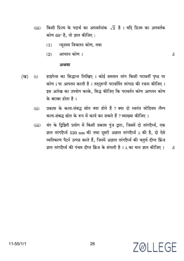
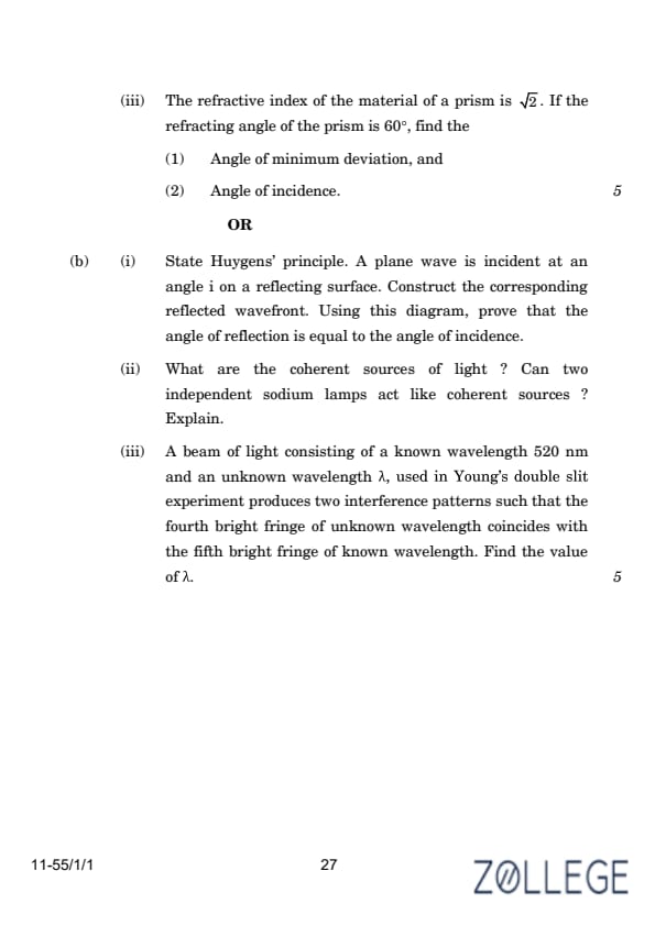
The refractive index of the material of a prism is √2. If the refracting angle of the prism is 60°, find:
- The angle of minimum deviation, and
- The angle of incidence.
Correct Answer: (1) Angle of minimum deviation: δm = 30°.
(2) Angle of incidence: i = 45°.
View Solution
(1): Angle of Minimum Deviation
The refractive index n of the material of the prism is related to the angle of the prism A and the angle of minimum deviation δm by the formula:
n = (sin((A + δm) / 2)) / (sin(A / 2)).
Substituting the given values:
- n = √2,
- A = 60°.
Rearranging the formula:
sin((A + δm) / 2) = n × sin(A / 2).
Calculating sin(A / 2):
A / 2 = 60° / 2 = 30°, sin(30°) = 1/2.
Substituting:
sin((A + δm) / 2) = √2 × (1/2) = √2 / 2.
The angle whose sine is √2 / 2 is 45°:
(A + δm) / 2 = 45°.
Solving for δm:
A + δm = 90° → δm = 90° - 60° = 30°.
Thus, the angle of minimum deviation is:
δm = 30°.
(2): Angle of Incidence
At the angle of minimum deviation, the angle of incidence i is equal to the angle of emergence. Using the geometry of the prism, the relation between the angle of incidence, the angle of refraction r, and the prism angle A is:
r = A / 2.
Substituting A = 60°:
r = 60° / 2 = 30°.
Using Snell's law at the first face of the prism:
n = (sin i) / (sin r).
Rearranging for i:
sin i = n × sin r.
Substituting:
sin i = √2 × sin(30°) = √2 × (1/2) = √2 / 2.
The angle whose sine is √2 / 2 is 45°:
i = 45°.
Thus, the angle of incidence is:
i = 45°.
State Huygens’ principle. A plane wave is incident at an angle i on a reflecting surface. Construct the corresponding reflected wavefront. Using this diagram, prove that the angle of reflection is equal to the angle of incidence.
Correct Answer: The angle of reflection is equal to the angle of incidence: θr = θi.
View Solution
Huygens’ Principle and Angle of Reflection
Huygens’ principle states that every point on a wavefront acts as a source of secondary wavelets, which spread out in all directions with the same speed as the wave. The new wavefront is the envelope of these secondary wavelets.
Diagram:
In the diagram, consider:
- The incident wavefront AB approaching the reflecting surface at an angle θi,
- The reflected wavefront CD leaving the surface at an angle θr.
From the geometry of the wavefronts:
θr = θi.
Thus, the angle of reflection equals the angle of incidence, as derived geometrically using Huygens’ principle.
What are the coherent sources of light? Can two independent sodium lamps act like coherent sources? Explain.
Correct Answer: Coherent sources have a constant phase difference. Two independent sodium lamps cannot act as coherent sources.
View Solution
Coherent Sources of Light
Coherent sources of light are sources that emit waves with:
- A constant phase difference,
- The same frequency.
Explanation: Two independent sodium lamps cannot act as coherent sources because their emissions are random and do not maintain a constant phase difference. Only light derived from a single source (e.g., using a beam splitter) can produce coherent sources.
A beam of light consisting of a known wavelength 520 nm and an unknown wavelength λ, used in Young’s double slit experiment, produces two interference patterns such that the fourth bright fringe of unknown wavelength coincides with the fifth bright fringe of known wavelength. Find the value of λ.
View Solution
Finding the Unknown Wavelength λ
In Young’s double slit experiment, the position of the bright fringes is determined by:
x = n × (λD / d),
where:
- n is the fringe order,
- λ is the wavelength of light,
- D is the distance between the slits and the screen,
- d is the distance between the slits.
For the fourth bright fringe of the unknown wavelength to coincide with the fifth bright fringe of the known wavelength:
4λ = 5 × 520 nm.
Solving for λ:
λ = (5 × 520) / 4 = 650 nm.
Thus, the unknown wavelength λ is 650 nm.
*The article might have information for the previous academic years, please refer the official website of the exam.