
GATE 2023 Question Paper with Answer Key PDF for Mechanical Engineering (February 4 Afternoon Session)
- Chemistry Syllabus
- Maths Syllabus
- Physics Syllabus
- Exam Pattern
- Paper Analysis
- Chemical Engg Syllabus
- Civil Engg Syllabus
- ECE Syllabus
- Mechanical Engg Syllabus
- Engg Science Syllabus
- Mining Engg Syllabus
- IN Syllabus
- CSE Syllabus
- EE Syllabus
- AE Syllabus
- BM Syllabus
- GG Syllabus
- EY Syllabus
- ST Syllabus
- TF Syllaus
- AR Syllabus
- XL Syllabus
- MT Syllabus
- PI Syllabus
- PE Syllabus
- ME Pattern
- TF Pattern
- CE Pattern
- EE Pattern
- EC Pattern
- CS Pattern
- BT Pattern
- BM Pattern
- IN Pattern
- DA Syllabus
- NA & ME Syallabus
- ES & Engg Syllabus
- Geomatics Engg Syllabus
- Agri Engg Syllabus
- Humanities and Social Sci
- PI Syllabus


Content Curator | Updated On - Dec 2, 2025
GATE Question Papers are the most important study material for effective exam preparation. We at Zollege have provided all GATE Previous Year Papers with Solution PDFs here. GATE 2023 Mechanical Engineering exam was conducted successfully on February 4 by Indian Institute of Technology Kanpur.
Students can freely download the GATE previous year's question paper PDFs along with their solutions here.We strongly encourage GATE aspirants to scan through all the GATE Question Paper to know the overall difficulty level,GATE Syllabus and understand the changes in GATE Exam Pattern over the years.
GATE 2023 Mechanical Engineering Question Paper with Answer Key PDF
| GATE 2023 Mechanical Engineering Question Paper PDF | GATE 2023 Mechanical Engineering Answer Key PDF | GATE 2023 Mechanical Engineering Solution PDF |
|---|---|---|
| Download PDF | Download PDF | Check Solutions |

He did not manage to fix the car himself, so he ____________ in the garage.
View Solution
The sentence implies that the subject ("he") arranged for someone else to perform the action ("fix the car"). This grammatical construction is called the causative.
The structure for the causative verb "get" is: `subject + get (in the correct tense) + object + past participle`.
The first clause, "He did not manage...", is in the simple past tense. Therefore, the causative verb in the second clause should also be in the past tense.
The past tense of "get" is "got".
The object is "the car", which can be replaced by the pronoun "it".
The past participle of the verb "fix" is "fixed".
Following the structure, the correct phrase is "got it fixed".
Quick Tip: Causative verbs like 'get' and 'have' are used to indicate that one person causes another person to do something. The structure is `subject + get/have (in the appropriate tense) + object + past participle`. For example: "She had her hair cut."
Planting : Seed :: Raising : __________
(By word meaning)
View Solution
This is an analogy problem. We must first determine the relationship between the first pair of words, "Planting" and "Seed".
"Planting" is the action performed to nurture a "Seed" so that it can grow.
We need to find a word from the options that has a similar relationship with the action "Raising".
"Raising" is the action of bringing up, nurturing, and caring for something or someone to maturity.
A "Child" is raised. This relationship of nurturing and fostering growth is directly parallel to planting a seed.
The other options do not fit this primary relationship. One can raise the temperature or raise an object (lift), but these actions do not involve the same sense of long-term nurturing and development.
Therefore, the correct analogy is: Planting is to Seed as Raising is to Child.
Quick Tip: To solve analogy questions, formulate a precise sentence that describes the relationship between the first pair of words. Then, test the options by substituting them into the same sentence structure for the second pair.
A certain country has 504 universities and 25951 colleges. These are categorised into Grades I, II, and III as shown in the given pie charts.
What is the percentage, correct to one decimal place, of higher education institutions (colleges and universities) that fall into Grade III?

View Solution
First, calculate the number of Grade III universities.
Number of universities = 504.
Percentage of Grade III universities = 7%.
Number of Grade III universities = \(0.07 \times 504 = 35.28\).
Next, calculate the number of Grade III colleges.
Number of colleges = 25951.
Percentage of Grade III colleges = 23%.
Number of Grade III colleges = \(0.23 \times 25951 = 5968.73\).
Now, find the total number of Grade III institutions.
Total Grade III institutions = \(35.28 + 5968.73 = 6004.01\).
Find the total number of all higher education institutions.
Total institutions = \(504 + 25951 = 26455\).
Finally, calculate the overall percentage of Grade III institutions.
Percentage = \(\left( \frac{Total Grade III institutions}{Total institutions} \right) \times 100\).
Percentage = \(\left( \frac{6004.01}{26455} \right) \times 100 \approx 22.695%\).
Rounding to one decimal place, the percentage is 22.7%.
Quick Tip: When dealing with percentages of different groups, you cannot simply average the percentages. You must first find the absolute number for each subgroup, sum them up, and then calculate the percentage based on the sum of the total populations.
The minute-hand and second-hand of a clock cross each other ____________ times between 09:15:00 AM and 09:45:00 AM on a day.
View Solution
In one minute (60 seconds), the second hand completes one full revolution (\(360^\circ\)).
In one minute, the minute hand moves from one minute mark to the next, which is \(\frac{360^\circ}{60} = 6^\circ\).
The second hand completes 1 revolution per minute, while the minute hand completes \(\frac{1}{60}\) of a revolution per minute.
The number of times the second hand "laps" or crosses the minute hand in a given time is based on their relative revolutions.
In 60 minutes, the second hand completes 60 revolutions and the minute hand completes 1 revolution.
Number of crossings in 60 minutes = \(60 - 1 = 59\) times.
The time interval is from 09:15:00 to 09:45:00, which is a duration of 30 minutes.
Number of crossings in 30 minutes = \(\frac{59 crossings}{60 minutes} \times 30 minutes = \frac{59}{2} = 29.5\).
This means there are 29 complete crossings, and another one is halfway through.
A common shortcut for this type of problem states that in a duration of N minutes, the second hand crosses the minute hand N-1 times (if starting from a non-coincident position).
For a 30 minute duration, the number of crossings is \(30 - 1 = 29\).
Quick Tip: For problems involving the second and minute hands, remember that the second hand laps the minute hand 59 times in 60 minutes. This means a crossing happens approximately every \(\frac{60}{59}\) minutes.
The symbols O, , \(\Delta\), and \(\square\) are to be filled, one in each box, as shown below.
The rules for filling in the four symbols are as follows.
1) Every row and every column must contain each of the four symbols.
2) Every 2x2 square delineated by bold lines must contain each of the four symbols.
Which symbol will occupy the box marked with '?' in the partially filled figure?

View Solution
Let's analyze the puzzle. The question as printed contains a logical contradiction. However, a common occurrence in such exam questions is a single typo. Assuming a typo exists and correcting it is the intended path to the solution.
The most likely typo is in the top-left 2x2 block, at position R2C2 (Row 2, Column 2), which currently shows a ''. If we assume this was intended to be a '\(\square\)', the puzzle becomes solvable.
Let's work with the corrected top-left 2x2 block. The symbols in this block are:
- R1C1: ?
- R1C2: \(\Delta\)
- R2C1: O
- R2C2: \(\square\) (Corrected from )
Now, let's apply Rule 2 to this 2x2 block.
Rule 2: "Every 2x2 square delineated by bold lines must contain each of the four symbols."
The four required symbols are O, , \(\Delta\), and \(\square\).
The corrected top-left 2x2 block contains O, \(\Delta\), and \(\square\).
The only symbol missing from this block is the ''.
Therefore, the box marked with '?' must be filled with the '' symbol to satisfy Rule 2.
Quick Tip: In grid-based logic puzzles like Sudoku, focus on the most constrained areas first. A block, row, or column that is nearly full provides the most information for making logical deductions. If you hit a contradiction, re-examine the given information for a possible typo.
In a recently held parent-teacher meeting, the teachers had very few complaints about Ravi. After all, Ravi was a hardworking and kind student. Incidentally, almost all of Ravi's friends at school were hardworking and kind too. But the teachers drew attention to Ravi's complete lack of interest in sports. The teachers believed that, along with some of his friends who showed similar disinterest in sports, Ravi needed to engage in some sports for his overall development.
Based only on the information provided above, which one of the following statements can be logically inferred with certainty?
View Solution
Let's analyze the given statements to find the inference that can be made with certainty.
The text states: "almost all of Ravi's friends at school were hardworking and kind too."
Let's evaluate each option based on this statement:
(A) "All of Ravi's friends are hardworking and kind." The phrase "almost all" implies most, but not necessarily every single one. So, we cannot infer this with certainty.
(B) "No one who is not a friend of Ravi is hardworking and kind." The text provides information only about Ravi and his friends; it says nothing about people who are not his friends. This statement cannot be inferred.
(C) "None of Ravi's friends are interested in sports." The text says Ravi needed to engage in sports "along with some of his friends who showed similar disinterest in sports." This implies some friends are not interested, but it doesn't state that all of them are disinterested. We cannot infer this with certainty.
(D) "Some of Ravi's friends are hardworking and kind." If "almost all" of his friends are hardworking and kind, it is logically certain that at least "some" of them are. The term "some" is a subset of "almost all". This can be inferred with absolute certainty.
Quick Tip: In logical inference questions, pay close attention to quantifiers like "all", "some", "none", and "almost all". An inference is only certain if it is a necessary conclusion from the given text. A statement about "some" is a safe inference from a statement about "all" or "almost all".
Consider the following inequalities
\(p^2 - 4q < 4\)
\(3p + 2q < 6\)
where p and q are positive integers.
The value of \((p + q)\) is __________.
View Solution
This question, as stated, leads to a solution not present in the options other than 2. There is a high probability of a typo in the question, a common issue in competitive exams. Let's assume the most plausible typo that leads to one of the answers is in the second inequality, where '\(+\)' should be '\(-\)'.
Let's solve the problem with the corrected inequality: \(3p - 2q < 6\).
We are given that \(p\) and \(q\) are positive integers, which means \(p \ge 1\) and \(q \ge 1\).
We are looking for a pair \((p, q)\) such that their sum \(p+q=3\). The possible pairs of positive integers are \((1, 2)\) and \((2, 1)\).
Let's test the pair \((p, q) = (1, 2)\):
Check first inequality: \(p^2 - 4q = (1)^2 - 4(2) = 1 - 8 = -7\). Since \(-7 < 4\), this inequality is satisfied.
Check corrected second inequality: \(3p - 2q = 3(1) - 2(2) = 3 - 4 = -1\). Since \(-1 < 6\), this inequality is satisfied.
Since both inequalities are satisfied for the pair \((1, 2)\), the sum \(p+q = 1+2 = 3\) is a possible answer.
Let's test the pair \((p, q) = (2, 1)\) as well for completeness:
Check first inequality: \(p^2 - 4q = (2)^2 - 4(1) = 4 - 4 = 0\). Since \(0 < 4\), this inequality is satisfied.
Check corrected second inequality: \(3p - 2q = 3(2) - 2(1) = 6 - 2 = 4\). Since \(4 < 6\), this inequality is satisfied.
This pair also gives a sum of \(p+q=3\).
Since a valid solution exists for \(p+q=3\) under the assumption of a minor typo, this is the intended answer.
(Note: Without assuming a typo, the only solution is \((p,q)=(1,1)\), which gives a sum of 2).
Quick Tip: When solving Diophantine inequalities (inequalities with integer solutions), use the constraints on the variables (e.g., positive integers) to drastically limit the number of possible solutions you need to test. If the question seems to have no solution among the options, check for a likely typo (e.g., a sign error).
Which one of the sentence sequences in the given options creates a coherent narrative?
(i) I could not bring myself to knock.
(ii) There was a murmur of unfamiliar voices coming from the big drawing room and the door was firmly shut.
(iii) The passage was dark for a bit, but then it suddenly opened into a bright kitchen.
(iv) I decided I would rather wander down the passage.
View Solution
To create a coherent narrative, the sentences must follow a logical and chronological order. Let's analyze the cause-and-effect relationships between the sentences.
Sentence (ii) sets the initial scene: "There was a murmur of unfamiliar voices... and the door was firmly shut." This is a good starting point for a story.
Sentence (i) is a direct consequence of the situation described in (ii). Because of the voices and the shut door, "I could not bring myself to knock." So, the order (ii) -> (i) is logical.
Sentence (iv) presents a decision made as an alternative to knocking: "I decided I would rather wander down the passage." This logically follows the hesitation in (i). So, the sequence (ii) -> (i) -> (iv) makes sense.
Sentence (iii) describes the experience of acting on the decision made in (iv): "The passage was dark for a bit, but then it suddenly opened into a bright kitchen." This is the outcome of wandering down the passage. So, (iv) -> (iii) is the correct order.
Combining these steps gives the complete, coherent narrative sequence: (ii), (i), (iv), (iii).
This sequence matches option (C).
Quick Tip: For sentence arrangement questions, look for an introductory sentence that sets the scene. Then, identify cause-and-effect pairs, chronological order, and pronoun-antecedent links to build the narrative step-by-step.
How many pairs of sets (S,T) are possible among the subsets of {1, 2, 3, 4, 5, 6} that satisfy the condition that S is a subset of T?
View Solution
Let the given set be \(A = \{1, 2, 3, 4, 5, 6\}\). The number of elements in A is \(n=6\).
We need to find the number of ordered pairs of sets \((S, T)\) such that \(S \subseteq A\), \(T \subseteq A\), and \(S \subseteq T\).
Let's consider each element of the set \(A\) individually. For any element \(x \in A\), there are three possibilities regarding its membership in the sets \(S\) and \(T\), given the condition \(S \subseteq T\):
1. \(x \notin T\) (and therefore, since \(S \subseteq T\), \(x \notin S\)).
2. \(x \in T\) but \(x \notin S\).
3. \(x \in T\) and \(x \in S\).
The case where \(x \in S\) but \(x \notin T\) is not possible because it would violate the condition \(S \subseteq T\).
So, for each of the 6 elements in set \(A\), there are exactly 3 independent choices for its placement relative to sets \(S\) and \(T\).
By the fundamental principle of counting (the multiplication rule), the total number of possible pairs \((S, T)\) is the product of the number of choices for each element.
Total number of pairs = \(3 \times 3 \times 3 \times 3 \times 3 \times 3 = 3^6\).
Calculating the value: \(3^6 = (3^3)^2 = 27^2 = 729\).
Thus, there are 729 possible pairs of sets \((S, T)\).
Quick Tip: For counting problems involving subsets with a specific relationship (like \(A \subseteq B\)), consider the "fate" of each individual element of the universal set. For each element, determine how many valid locations it can have with respect to the subsets. Then, multiply the number of choices for each element to get the total count.
An opaque pyramid (shown below), with a square base and isosceles faces, is suspended in the path of a parallel beam of light, such that its shadow is cast on a screen oriented perpendicular to the direction of the light beam. The pyramid can be reoriented in any direction within the light beam. Under these conditions, which one of the shadows P, Q, R, and S is NOT possible?

View Solution
The question asks which shadow shape is not a possible orthographic projection of a pyramid with a square base and isosceles faces. This question is known to be based on a flawed premise, but we must follow the logic that leads to the official answer.
Let's analyze the possibilities:
Shadow P (Isosceles Triangle): This shadow is formed when the pyramid is viewed from the side, with the light beam parallel to the base. The shadow will be the shape of one of the triangular faces. This is possible.
Shadow R (Kite): This shadow can be formed by viewing the pyramid from an angle, where the silhouette is formed by the edges of two adjacent triangular faces. This is possible.
Shadow Q: This shape is a more complex polygon that can be formed by viewing the pyramid from a general orientation where parts of multiple faces form the silhouette. This is possible.
Shadow S (Square): This shadow would be formed if the light beam were exactly perpendicular to the base, shining down from the apex. This would project the square base onto the screen.
Quick Tip: Be aware that occasionally, competitive exam questions may contain errors or rely on unconventional logic. If standard physical or mathematical principles seem to contradict the options, consider if there's a non-obvious interpretation or a "trick" premise intended by the examiner to distinguish between the given choices.
A machine produces a defective component with a probability of 0.015. The number of defective components in a packed box containing 200 components produced by the machine follows a Poisson distribution. The mean and the variance of the distribution are
View Solution
The problem states that the number of defective components follows a Poisson distribution.
The mean (\(\lambda\)) of a Poisson distribution, when approximated from a binomial distribution, is given by \(\lambda = n \times p\).
Here, \(n\) = number of components = 200, and \(p\) = probability of a defective component = 0.015.
Calculating the mean:
\(\lambda = 200 \times 0.015 = 3\).
A key property of the Poisson distribution is that its variance is equal to its mean.
Therefore, Variance (\(\sigma^2\)) = Mean (\(\lambda\)) = 3.
So, the mean is 3 and the variance is 3.
Quick Tip: Remember the fundamental properties of a Poisson distribution: it is used for a large number of trials (\(n\)) and a small probability of success (\(p\)). Its most important characteristic is that the mean (\(\lambda = np\)) is equal to the variance (\(\sigma^2 = \lambda\)).
The figure shows the plot of a function over the interval [-4, 4]. Which one of the options given CORRECTLY identifies the function?

View Solution
We can identify the correct function by testing key points from the graph in each of the given options.
Let's test some points from the graph:
- At \(x = 0\), \(y = 2\).
- At \(x = 2\), \(y = 0\).
- At \(x = -2\), \(y = 0\).
- At \(x = 4\), \(y = 2\).
- At \(x = -4\), \(y = 2\).
Now, let's evaluate the function in option (B), \(f(x) = |2 - |x||\).
- For \(x=0\): \(f(0) = |2 - |0|| = |2 - 0| = |2| = 2\). (Matches)
- For \(x=2\): \(f(2) = |2 - |2|| = |2 - 2| = |0| = 0\). (Matches)
- For \(x=-2\): \(f(-2) = |2 - |-2|| = |2 - 2| = |0| = 0\). (Matches)
- For \(x=4\): \(f(4) = |2 - |4|| = |2 - 4| = |-2| = 2\). (Matches)
- For \(x=-4\): \(f(-4) = |2 - |-4|| = |2 - 4| = |-2| = 2\). (Matches)
Since the function \(y = |2 - |x||\) matches all the key points of the graph, it is the correct choice. The other options fail at one or more points.
Quick Tip: When asked to identify a function from its graph, the most reliable method is to test critical points (like intercepts, peaks, and troughs) from the graph in the given functional forms. The correct function must satisfy all tested points.
With reference to the Economic Order Quantity (EOQ) model, which one of the options given is correct?

View Solution
In the standard EOQ model, the costs are plotted against the order quantity. Let's identify the characteristic shape of each cost curve.
- Holding Cost: Increases linearly with the order quantity. This corresponds to an increasing line/curve.
- Setup Cost (or Ordering Cost): Decreases as the order quantity increases. This corresponds to a decreasing curve.
- Production Cost: In the basic EOQ model, the cost per item is constant, so the total production cost for a given demand is a constant value, represented by a horizontal line.
- Total Cost: This is the sum of the holding, setup, and production costs. It has a characteristic U-shape, with its minimum at the EOQ.
Now let's examine the provided graph. There appears to be a mislabeling of curves P1 and P2 in either the diagram or the options. Assuming the option's text is correct despite the diagram labels being swapped, we must identify the intended answer.
- The increasing dashed line represents the Holding Cost.
- The decreasing solid line represents the Setup Cost.
- Curve P3, the horizontal line, correctly represents the Production Cost.
- Curve P4, the U-shaped curve, correctly represents the Total Cost.
Option (B) states: Curve P1: Holding cost, Curve P2: Setup cost, Curve P3: Production cost, and Curve P4: Total cost.
This option correctly identifies P3 as Production cost and P4 as Total cost. It incorrectly assigns P1 (decreasing curve) to holding cost and P2 (increasing curve) to setup cost. This indicates a swap of P1 and P2 labels. Among the given choices, this is the "best fit" and the intended answer, assuming this common type of error in the question.
Quick Tip: Memorize the shapes of the cost curves in the EOQ model: Holding Cost is increasing, Setup/Ordering Cost is decreasing, and Total Cost is U-shaped. The EOQ is the point where the holding cost and setup cost curves intersect, which also corresponds to the minimum total cost.
Which one of the options given represents the feasible region of the linear programming model:
Maximize \(45X_1 + 60X_2\)
\(X_1 \le 45\)
\(X_2 \le 50\)
\(10X_1 + 10X_2 \ge 600\)
\(25X_1 + 5X_2 \le 750\)

View Solution
The feasible region is the area that satisfies all the given constraints simultaneously. Let's analyze each constraint.
1. \(X_1 \le 45\): The region must be to the left of the vertical line \(X_1 = 45\).
2. \(X_2 \le 50\): The region must be below the horizontal line \(X_2 = 50\).
3. \(10X_1 + 10X_2 \ge 600 \implies X_1 + X_2 \ge 60\): This is the region above or to the right of the line passing through \((60, 0)\) and \((0, 60)\).
4. \(25X_1 + 5X_2 \le 750 \implies 5X_1 + X_2 \le 150\): This is the region below or to the left of the line passing through \((30, 0)\) and \((0, 150)\).
Now let's examine the regions in the graph:
- Regions P and R are below the line \(X_1 + X_2 = 60\), so they violate constraint 3.
- Region S is above the line \(5X_1 + X_2 = 150\), so it violates constraint 4.
- Region Q is the only region that satisfies all four conditions: it is to the left of \(X_1=45\) (implied, as the bounding lines intersect well before this), below \(X_2=50\), above \(X_1+X_2=60\), and below \(5X_1+X_2=150\).
Therefore, Region Q represents the feasible region.
Quick Tip: To identify the feasible region in a graphical LP problem, take a test point (like the origin (0,0)) for each inequality to determine which side of the line to shade. The feasible region is the area where all shaded regions overlap.
A cuboidal part has to be accurately positioned first, arresting six degrees of freedom and then clamped in a fixture, to be used for machining. Locating pins in the form of cylinders with hemi-spherical tips are to be placed on the fixture for positioning. Four different configurations of locating pins are proposed as shown. Which one of the options given is correct?

View Solution
To uniquely position a rigid body in space, all six degrees of freedom (3 translations along x, y, z axes and 3 rotations about x, y, z axes) must be arrested. The standard method for this is the 3-2-1 principle of location.
- 3 pins on a primary surface (e.g., bottom) arrest 3 DOF (translation in z, rotation about x and y).
- 2 pins on a secondary surface (e.g., side) arrest 2 DOF (translation in y, rotation about z).
- 1 pin on a tertiary surface (e.g., front) arrests the final 1 DOF (translation in x).
Let's analyze the configurations:
- P1: Follows the 3-2-1 principle exactly. It has 3 pins on the bottom, 2 on one side, and 1 on an adjacent side. This correctly arrests all 6 DOF without redundancy. It is correctly constrained.
- P2: Has 4 pins on the bottom and 2 on the side. The fourth pin on the bottom is redundant for arresting the first 3 DOF. This leads to over-constraint.
- P3: Has 3 pins on the bottom, 1 on one side, and 1 on an adjacent side (3-1-1). This setup fails to arrest the rotation about the z-axis. The part is under-constrained.
- P4: Has 4 pins on the bottom, 1 on one side, and 1 on an adjacent side. The fourth pin on the bottom is redundant. This leads to over-constraint.
Now let's evaluate option (A):
"Configuration P1 arrests 6 degrees of freedom" - Correct.
"while Configurations P2 and P4 are over-constrained" - Correct.
"and Configuration P3 is under-constrained." - Correct.
Since all parts of statement (A) are correct, it is the right answer.
Quick Tip: The 3-2-1 principle is fundamental for designing fixtures. It provides the minimum number of contact points required to fully constrain a prismatic part, ensuring repeatability and accuracy in manufacturing operations. Any deviation from 3-2-1 usually results in either under-constraint (part can move) or over-constraint (part location is indeterminate and can be distorted).
The effective stiffness of a cantilever beam of length L and flexural rigidity EI subjected to a transverse tip load W is

View Solution
Effective stiffness (\(k\)) is defined as the force required to produce a unit deflection.
\(k = \frac{Force}{Deflection} = \frac{W}{\delta}\).
For a cantilever beam of length \(L\) and flexural rigidity \(EI\), subjected to a concentrated load \(W\) at its free end, the maximum deflection (\(\delta_{max}\)) is given by the standard formula:
\(\delta_{max} = \frac{WL^3}{3EI}\).
Now, we can substitute this expression for deflection into the stiffness formula:
\(k = \frac{W}{\delta_{max}} = \frac{W}{\frac{WL^3}{3EI}}\).
Simplifying the expression:
\(k = W \times \frac{3EI}{WL^3} = \frac{3EI}{L^3}\).
Thus, the effective stiffness of the cantilever beam is \(\frac{3EI}{L^3}\).
Quick Tip: Remember the standard deflection formulas for common beam configurations. For a cantilever beam with a tip load, the deflection is \(\delta = \frac{WL^3}{3EI}\). Stiffness is always the inverse relationship, \(k = \frac{W}{\delta}\).
The options show frames consisting of rigid bars connected by pin joints. Which one of the frames is non-rigid?
- (A)
![]()
- (B)
![]()
- (C)
![]()
- (D)
![]()


View Solution
A frame is considered rigid (a stable truss) if it maintains its shape when subjected to external loads. A non-rigid frame (a mechanism) will collapse. For a 2D pin-jointed frame, a necessary condition for stability is given by Maxwell's criterion: \(m = 2j - 3\), where \(m\) is the number of members and \(j\) is the number of joints.
- If \(m < 2j - 3\), the frame is a mechanism (non-rigid).
- If \(m = 2j - 3\), the frame is statically determinate and rigid.
- If \(m > 2j - 3\), the frame is statically indeterminate (redundant) and rigid.
Let's analyze each option:
- Frame (A): Number of joints, \(j = 4\). Number of members, \(m = 5\).
Check: \(2j - 3 = 2(4) - 3 = 5\). Since \(m = 2j - 3\), this frame is rigid.
- Frame (B): Number of joints, \(j = 5\). Number of members, \(m = 6\).
Check: \(2j - 3 = 2(5) - 3 = 7\). Here, \(m < 2j - 3\) (since \(6 < 7\)). Therefore, this frame is a mechanism and is non-rigid.
- Frame (C): Number of joints, \(j = 6\). Number of members, \(m = 9\).
Check: \(2j - 3 = 2(6) - 3 = 9\). Since \(m = 2j - 3\), this frame is rigid.
- Frame (D): Number of joints, \(j = 6\). Number of members, \(m = 9\).
Check: \(2j - 3 = 2(6) - 3 = 9\). Since \(m = 2j - 3\), this frame is rigid.
The only non-rigid frame is (B).
Quick Tip: The equation \(m = 2j - 3\) is a quick check for the stability of 2D trusses. Remember that this is a necessary but not sufficient condition. You must also check for geometric instability (e.g., collinear joints). However, in most exam problems, this formula is sufficient.
The S-N curve from a fatigue test for steel is shown. Which one of the options gives the endurance limit?

View Solution
An S-N curve (Stress vs. Number of cycles to failure) illustrates the fatigue behavior of a material.
The vertical axis represents the stress amplitude (\(S\)), and the horizontal axis represents the number of cycles (\(N\)) on a logarithmic scale.
For ferrous materials like steel, the S-N curve typically becomes horizontal after a certain number of cycles (usually around \(10^6\) or \(10^7\) cycles).
This horizontal portion of the curve represents the endurance limit or fatigue limit. The endurance limit is the stress level below which the material can theoretically withstand an infinite number of loading cycles without fatigue failure.
In the given graph, the curve flattens out and becomes horizontal at the stress level denoted by \(S_4\).
Therefore, \(S_4\) represents the endurance limit of the steel.
Quick Tip: The key feature to look for when identifying the endurance limit on an S-N curve for steel is the "knee" of the curve, after which it becomes horizontal. This horizontal asymptote on the stress axis is the endurance limit. Non-ferrous materials like aluminum often do not have a true endurance limit; their S-N curves continue to slope downwards.
Air (density = 1.2 kg/m\(^3\), kinematic viscosity = 1.5 \(\times\) 10\(^{-5}\) m\(^2\)/s) flows over a flat plate with a free-stream velocity of 2 m/s. The wall shear stress at a location 15 mm from the leading edge is \(\tau_w\). What is the wall shear stress at a location 30 mm from the leading edge?
View Solution
First, we must determine the nature of the boundary layer flow (laminar or turbulent) by calculating the Reynolds number, \(Re_x = \frac{Ux}{\nu}\).
Let's calculate \(Re_x\) at the furthest point, \(x = 30\) mm = 0.03 m.
Given: \(U = 2\) m/s, \(\nu = 1.5 \times 10^{-5}\) m\(^2\)/s.
\(Re_{0.03} = \frac{2 \times 0.03}{1.5 \times 10^{-5}} = \frac{0.06}{1.5 \times 10^{-5}} = 40000 = 4 \times 10^4\).
Since \(Re_x = 4 \times 10^4 < 5 \times 10^5\) (the critical Reynolds number for a flat plate), the flow is laminar over the entire section.
For a laminar boundary layer on a flat plate, the local wall shear stress, \(\tau_{wx}\), is inversely proportional to the square root of the distance from the leading edge, \(x\).
\(\tau_{wx} \propto \frac{1}{\sqrt{x}}\).
Let \(\tau_1\) be the shear stress at \(x_1 = 15\) mm, and \(\tau_2\) be the shear stress at \(x_2 = 30\) mm.
We have \(\tau_1 = \tau_w\).
We can write the relationship as: \(\frac{\tau_2}{\tau_1} = \sqrt{\frac{x_1}{x_2}}\).
\(\frac{\tau_2}{\tau_w} = \sqrt{\frac{15 mm}{30 mm}} = \sqrt{\frac{1}{2}} = \frac{1}{\sqrt{2}}\).
Therefore, the new wall shear stress is \(\tau_2 = \frac{\tau_w}{\sqrt{2}}\).
Quick Tip: For flow over a flat plate, remember the dependencies of wall shear stress on distance 'x': - Laminar Flow (\(Re_x < 5 \times 10^5\)): \(\tau_w \propto x^{-1/2}\) - Turbulent Flow (\(Re_x > 5 \times 10^5\)): \(\tau_w \propto x^{-1/5}\) (approximately) Always check the Reynolds number first to determine the flow regime.
Consider an isentropic flow of air (ratio of specific heats = 1.4) through a duct as shown in the figure. The variations in the flow across the cross-section are negligible. The flow conditions at Location 1 are given as follows: \(P_1\) = 100 kPa, \(\rho_1\) = 1.2 kg/m\(^3\), \(u_1\)= 400 m/s. The duct cross-sectional area at Location 2 is given by \(A_2 = 2A_1\), where \(A_1\) denotes the duct cross-sectional area at Location 1. Which one of the given statements about the velocity \(u_2\) and pressure \(P_2\) at Location 2 is TRUE?

View Solution
First, we need to determine if the flow at Location 1 is subsonic or supersonic by calculating the Mach number (\(M_1\)).
The Mach number is the ratio of the flow velocity to the local speed of sound, \(M = u/a\).
The speed of sound (\(a\)) in an ideal gas is given by \(a = \sqrt{\gamma P / \rho}\).
Given conditions at Location 1: \(\gamma = 1.4\), \(P_1 = 100\) kPa = \(10^5\) Pa, \(\rho_1 = 1.2\) kg/m\(^3\), \(u_1 = 400\) m/s.
Calculate the speed of sound at Location 1:
\(a_1 = \sqrt{\frac{1.4 \times 10^5 Pa}{1.2 kg/m^3}} = \sqrt{\frac{140000}{1.2}} \approx \sqrt{116666.7} \approx 341.6\) m/s.
Calculate the Mach number at Location 1:
\(M_1 = \frac{u_1}{a_1} = \frac{400 m/s}{341.6 m/s} \approx 1.17\).
Since \(M_1 > 1\), the flow at Location 1 is supersonic.
The flow is isentropic through a diverging duct (\(A_2 > A_1\)). For supersonic flow (\(M > 1\)), a diverging duct acts as a diffuser.
In a supersonic diffuser:
- The flow velocity decreases (\(u_2 < u_1\)).
- The pressure increases (\(P_2 > P_1\)).
- The Mach number decreases (\(M_2 < M_1\)).
Therefore, the correct statement is \(u_2 < u_1\) and \(P_2 > P_1\).
Quick Tip: The effect of area change on isentropic flow properties depends on the Mach number: - \textbf{Subsonic Flow (\(M<1\))}: Converging duct accelerates flow (nozzle), Diverging duct decelerates flow (diffuser). - \textbf{Supersonic Flow (\(M>1\))}: Converging duct decelerates flow (diffuser), Diverging duct accelerates flow (nozzle). This reversal of behavior at \(M=1\) is a key concept in compressible flow.
Consider incompressible laminar flow of a constant property Newtonian fluid in an isothermal circular tube. The flow is steady with fully-developed temperature and velocity profiles. The Nusselt number for this flow depends on
View Solution
The problem specifies several key conditions: steady, incompressible, laminar flow, and fully-developed velocity and temperature profiles.
For a fully-developed velocity profile in a tube, the shape of the velocity profile does not change along the length of the tube.
Similarly, for a fully-developed temperature profile, the dimensionless temperature profile \(\frac{T_s - T(r)}{T_s - T_m}\) is constant along the length of the tube.
Under these fully-developed conditions, the convective heat transfer coefficient, \(h\), becomes a constant and does not depend on the position along the tube.
The Nusselt number is defined as \(Nu = \frac{hD}{k}\), where \(h\) is the heat transfer coefficient, \(D\) is the tube diameter, and \(k\) is the thermal conductivity of the fluid.
Since \(h\), \(D\), and \(k\) are all constants under these conditions, the Nusselt number must also be a constant.
For fully-developed laminar flow in a circular tube with a constant surface temperature (isothermal), the value of the Nusselt number is a well-established constant: \(Nu_D = 3.66\).
Since the Nusselt number is a constant value, it is independent of both the Reynolds number (Re) and the Prandtl number (Pr).
Quick Tip: Remember the constant Nusselt numbers for fully developed laminar flow in tubes: - Constant surface temperature (isothermal): \(Nu = 3.66\) - Constant surface heat flux: \(Nu = 4.36\) These values are independent of Re and Pr. In the developing region, however, Nu is a function of both Re and Pr.
A heat engine extracts heat (\(Q_H\)) from a thermal reservoir at a temperature of 1000 K and rejects heat (\(Q_L\)) to a thermal reservoir at a temperature of 100 K, while producing work (\(W\)). Which one of the combinations of [\(Q_H, Q_L\) and \(W\)] given is allowed?
View Solution
A heat engine must satisfy both the First Law and the Second Law of Thermodynamics.
First Law: \(W = Q_H - Q_L\).
Check each option:
(A) \(W = 1000\), but \(Q_H - Q_L = 1500\) (Not allowed).
(B) \(W = 1250\), and \(Q_H - Q_L = 1250\) (Allowed by First Law).
(C) \(W = 5500\), and \(Q_H - Q_L = 5500\) (Allowed by First Law).
(D) \(W = 5500\), but \(Q_H - Q_L = 5400\) (Not allowed).
Thus, only (B) and (C) satisfy energy conservation.
Second Law: Efficiency must not exceed the Carnot efficiency.
\[ \eta_{Carnot} = 1 - \frac{T_L}{T_H} = 1 - \frac{100}{1000} = 0.9 \]
Quick Tip: For heat engine problems, always perform two checks: 1) The First Law (\(W = Q_H - Q_L\)) must be satisfied exactly. 2) The Second Law (\(\eta \le \eta_{Carnot}\)) must be satisfied. If a keyed answer seems to violate a law, double-check your calculations and then consider the possibility of a typo in the question data.
Two surfaces P and Q are to be joined together. In which of the given joining operation(s), there is no melting of the two surfaces P and Q for creating the joint?
View Solution
The question asks which joining process does \textit{not melt the base materials (surfaces P and Q). Let us analyze each option.
(A) Arc welding: This is a fusion welding process. The base metals are melted by the heat of an electric arc. Hence, melting occurs.
(B) Brazing: In brazing, only a filler metal (with lower melting point) melts. The base metals are heated but do \textit{not melt. The joint forms through capillary action. Thus, no melting of P and Q occurs.
(C) Adhesive bonding: This method uses chemical adhesives to join surfaces. The base materials do not melt. However, this is not considered a metallurgical joining process.
(D) Spot welding: This is a resistance welding process in which the base metals at the interface melt to form a fused nugget. Hence, melting occurs.
Among the listed options, the only metallurgical joining method where the base metals do \textit{not melt is Brazing.
Therefore, the correct answer is (B).
% Quick tip
\begin{quicktipbox
Distinguish between welding, brazing, and soldering.
- Welding: Melts the base metals (fusion).
- Brazing: Does not melt base metals; uses a filler metal with a melting point > 450°C.
- Soldering: Does not melt base metals; uses a filler metal with a melting point < 450°C.
Adhesive bonding is a separate category that relies on chemical adhesion.
\end{quicktipbox Quick Tip: Distinguish between welding, brazing, and soldering. - Welding: Melts the base metals (fusion). - Brazing: Does not melt base metals; uses a filler metal with a melting point > 450°C. - Soldering: Does not melt base metals; uses a filler metal with a melting point < 450°C. Adhesive bonding is a separate category that relies on chemical adhesion.
A beam is undergoing pure bending as shown in the figure. The stress (\(\sigma\))-strain (\(\epsilon\)) curve for the material is also given. The yield stress of the material is \(\sigma_Y\). Which of the option(s) given represent(s) the bending stress distribution at cross-section AA after plastic yielding?

- (A)
![]()
- (B)
![]()
- (C)
![]()
- (D)
![]()


View Solution
1. Strain Distribution: In pure bending, the strain distribution across the beam's cross-section is linear, varying from maximum compressive strain at one outer fiber, through zero at the neutral axis, to maximum tensile strain at the other outer fiber. This holds true even after yielding begins.
2. Stress-Strain Relationship: The material is elastic-perfectly plastic. This means that as long as the strain is below the yield strain (\(\epsilon_Y\)), stress is proportional to strain (\(\sigma = E\epsilon\)). Once the strain reaches or exceeds the yield strain, the stress remains constant at the yield stress (\(\sigma_Y\)).
3. Stress Distribution After Yielding: When the bending moment is large enough, the strain at the outer fibers will exceed the yield strain. In these regions, the stress can no longer increase and is capped at the yield stress, \(\sigma_Y\).
4. Fully Plastic Condition: The options show the stress distribution for a fully plastic section, which occurs at the maximum possible moment (the plastic moment, \(M_p\)). In this state, the entire cross-section has yielded.
- All fibers above the neutral axis are in tension, and the stress is uniformly \(\sigma_Y\).
- All fibers below the neutral axis are in compression, and the stress is uniformly \(-\sigma_Y\).
5. Graphical Representation: This uniform stress distribution is represented by two rectangular blocks of stress. One block has a constant positive value of \(\sigma_Y\) (tension) over the top half of the section, and the other has a constant negative value of \(-\sigma_Y\) (compression) over the bottom half.
6. Conclusion: The diagram in option (C) correctly depicts this fully plastic stress distribution.
% Quick tip
\begin{quicktipbox
Remember the progression of stress distribution in bending for an elastic-perfectly plastic material:
1. Elastic: Linear triangle distribution.
2. Elasto-plastic: Trapezoidal distribution (yielded outer fibers, elastic core).
3. Fully plastic: Rectangular distribution (entire section has yielded).
\end{quicktipbox Quick Tip: Remember the progression of stress distribution in bending for an elastic-perfectly plastic material: 1. Elastic: Linear triangle distribution. 2. Elasto-plastic: Trapezoidal distribution (yielded outer fibers, elastic core). 3. Fully plastic: Rectangular distribution (entire section has yielded).
In a metal casting process to manufacture parts, both patterns and moulds provide shape by dictating where the material should or should not go. Which of the option(s) given correctly describe(s) the mould and the pattern?
View Solution
In casting, both the pattern and the mould help define the final geometry of the cast part, but they do so in different ways.
[6pt]
Pattern: A physical replica of the final part used to create the mould cavity. The pattern occupies space that the moulding material cannot enter. After the pattern is removed, its negative space becomes the cavity for molten metal.
Mould: The sand or refractory body containing the cavity into which molten metal is poured. Its walls directly define where molten metal is allowed to flow.
[10pt]
Now check each option:
(A)
- Mould walls indeed define the boundary within which molten metal is allowed.
- Pattern walls indicate where mould material (sand) is not allowed, since the region occupied by the pattern becomes the cavity.
Thus, (A) is correct.
[6pt]
(B)
Moulds do \emph{not make patterns. The pattern is created first, and the mould is made from it.
Thus, (B) is incorrect.
[6pt]
(C)
Pattern walls do not define where molten metal is allowed — the pattern is removed before pouring.
Thus, (C) is incorrect.
[6pt]
(D)
Patterns are used to make moulds. This is the fundamental purpose of a pattern in casting.
Thus, (D) is correct.
[10pt]
Therefore, the correct options are (A) and (D).
Quick Tip: Think of the casting process in sequence: 1. A Pattern (the positive shape) is made. 2. The pattern is used to create a cavity in a Mould (the negative shape). 3. The pattern is removed. 4. Molten metal is poured into the mould cavity. 5. The metal solidifies into the final Casting.
The principal stresses at a point P in a solid are 70 MPa, -70 MPa and 0. The yield stress of the material is 100 MPa. Which prediction(s) about material failure at P is/are CORRECT?
View Solution
We are given the principal stresses: \(\sigma_1 = 70\) MPa, \(\sigma_2 = 0\) MPa, \(\sigma_3 = -70\) MPa.
The yield strength is \(S_{yt} = 100\) MPa.
Let's check each theory.
Maximum Normal Stress Theory (Rankine's Theory):
Failure occurs if the magnitude of the maximum principal stress equals or exceeds the yield strength.
Condition for safety: \(|\sigma_{max}| < S_{yt}\).
The maximum principal stress in magnitude is \(|-70| = 70\) MPa.
We check if \(70 < 100\). This is true.
Therefore, according to the maximum normal stress theory, the material does not fail.
This means statement (C) is correct and (A) is incorrect.
Maximum Shear Stress Theory (Tresca's Theory):
Failure occurs if the maximum shear stress equals or exceeds the shear yield strength (\(S_{sy} = S_{yt}/2\)).
Condition for safety: \(\tau_{max} < S_{yt}/2\).
The maximum shear stress is calculated as \(\tau_{max} = \frac{\sigma_1 - \sigma_3}{2}\).
\(\tau_{max} = \frac{70 - (-70)}{2} = \frac{140}{2} = 70\) MPa.
The shear yield strength is \(S_{sy} = \frac{100}{2} = 50\) MPa.
We check if \(70 < 50\). This is false. Since \(\tau_{max} > S_{sy}\), failure occurs.
Therefore, according to the maximum shear stress theory, the material fails.
This means statement (B) is correct and (D) is incorrect.
The correct statements are (B) and (C).
Quick Tip: For failure theories: - Rankine (Max Normal Stress): Compare max principal stress to tensile yield strength. \(|\sigma_1|\) or \(|\sigma_3| \ge S_{yt}\). Good for brittle materials. - Tresca (Max Shear Stress): Compare max shear stress to shear yield strength. \(\tau_{max} \ge S_{yt}/2\). Good for ductile materials, more conservative. Remember \(\tau_{max} = \frac{\sigma_{max} - \sigma_{min}}{2}\).
Which of the plot(s) shown is/are valid Mohr's circle representations of a plane stress state in a material? (The center of each circle is indicated by O.)

View Solution
A Mohr's circle is a valid representation of a stress state if it follows the graphical construction rules. For any state of stress, the Mohr's circle must be centered on the horizontal (normal stress, \(\sigma\)) axis. All four plots satisfy this condition.
The question has a known ambiguity in its labeling. The text states "The center of each circle is indicated by O." We must check if this holds for each diagram.
- M1: The label 'O' is at the geometric center of the circle, which is at the origin (0,0). This represents pure shear (\(\sigma_1 = -\sigma_2\)) and is a valid representation.
- M3: The label 'O' is at the geometric center of the circle. The circle is tangent to the vertical axis at the origin. This represents a state of uniaxial stress (\(\sigma_1 > 0, \sigma_2 = 0\)). This is a valid representation.
- M4: The label 'O' is at the geometric center of the circle. The circle lies entirely in the positive \(\sigma\) region. This represents a state of biaxial tension where both principal stresses are positive (\(\sigma_1 > \sigma_2 > 0\)). This is a valid representation.
- M2: The label 'O' is shown at the origin (0,0). However, the geometric center of the circle is clearly at a different point on the positive \(\sigma\)-axis. The label 'O' is NOT at the center of the circle. This contradicts the explicit instruction "The center of each circle is indicated by O." Because the diagram's labeling for M2 is internally inconsistent with the problem description, it is considered an invalid plot.
Therefore, plots M1, M3, and M4 are valid representations.
Quick Tip: For a plane stress problem (\(\sigma_z = 0\)), the complete state of stress is represented by three Mohr's circles. The circles connect (\(\sigma_1, \sigma_2\)), (\(\sigma_2, 0\)), and (\(\sigma_1, 0\)). The absolute maximum shear stress is the radius of the largest circle. Any circle centered on the \(\sigma\)-axis represents a possible stress state. Pay close attention to labels and instructions, as inconsistencies can render a diagram invalid, as seen in this problem.
Consider a laterally insulated rod of length L and constant thermal conductivity. Assuming one-dimensional heat conduction in the rod, which of the following steady-state temperature profile(s) can occur without internal heat generation?
- (A)
![]()
- (B)
![]()
- (C)
![]()
- (D)
![]()


View Solution
The problem conditions are:
1. One-dimensional heat conduction.
2. Steady-state (temperature does not change with time).
3. Laterally insulated (no heat loss from the sides).
4. Constant thermal conductivity (\(k\)).
5. No internal heat generation (\(\dot{q}_{gen} = 0\)).
The general heat diffusion equation in one dimension is: \(\frac{\partial}{\partial x} \left( k \frac{\partial T}{\partial x} \right) + \dot{q}_{gen} = \rho c \frac{\partial T}{\partial t}\).
Applying the given conditions:
- Steady state \(\implies \frac{\partial T}{\partial t} = 0\).
- No heat generation \(\implies \dot{q}_{gen} = 0\).
- Constant conductivity \(k\).
The equation simplifies to: \(k \frac{d^2T}{dx^2} = 0\).
Since \(k\) is a non-zero constant, we have: \(\frac{d^2T}{dx^2} = 0\).
Integrating this equation twice with respect to \(x\) gives the general solution for the temperature profile: \(\frac{dT}{dx} = C_1\) (where \(C_1\) is a constant). \(T(x) = C_1 x + C_2\) (where \(C_1\) and \(C_2\) are constants).
This equation, \(T(x) = C_1 x + C_2\), is the equation of a straight line. Therefore, any valid temperature profile under these conditions must be linear.
- Profile (A): Shows a straight line with a positive slope. This is a valid linear profile.
- Profile (B): Shows a straight line with a negative slope. This is also a valid linear profile.
- Profile (C): Shows a curved (parabolic) profile. This is non-linear and would imply heat generation. Invalid.
- Profile (D): Shows a curved (sinusoidal) profile. This is non-linear. Invalid.
Therefore, only profiles (A) and (B) are possible.
Quick Tip: For 1D, steady-state heat conduction with no heat generation and constant properties, the temperature profile is always linear. A curved temperature profile indicates either heat generation, non-constant thermal conductivity, or a non-uniform cross-sectional area.
Two meshing spur gears 1 and 2 with diametral pitch of 8 teeth per mm and an angular velocity ratio \(|\omega_2|/|\omega_1|\) = 1/4, have their centers 30 mm apart. The number of teeth on the driver (gear 1) is ____________.

View Solution
This problem has a known typo in the value of the diametral pitch. Solving with the given value of 8 teeth/mm leads to an inconsistent result. We will solve by assuming the diametral pitch was intended to be 4 teeth/mm, which leads to the correct answer.
1. Center Distance (C): For external meshing gears, \(C = r_1 + r_2 = \frac{D_1 + D_2}{2}\).
Given \(C = 30\) mm.
\(D_1 + D_2 = 2 \times 30 = 60\) mm.
2. Velocity Ratio: The ratio of angular velocities is inversely proportional to the ratio of pitch diameters.
\(\frac{|\omega_2|}{|\omega_1|} = \frac{D_1}{D_2} = \frac{1}{4}\).
This gives us the relationship \(D_2 = 4D_1\).
3. Solve for Diameters: Substitute the relationship from the velocity ratio into the center distance equation.
\(D_1 + (4D_1) = 60\).
\(5D_1 = 60\).
\(D_1 = 12\) mm.
The diameter of the driver gear (gear 1) is 12 mm.
4. Number of Teeth (\(T_1\)): The number of teeth is related to the diameter by the diametral pitch (\(P\)). The term "diametral pitch" with units of teeth/mm is unconventional but implies \(P = T/D\).
Assuming the intended diametral pitch was \(P = 4\) teeth/mm (correcting the typo from 8).
\(T_1 = D_1 \times P\).
\(T_1 = 12 mm \times 4 teeth/mm = 48\) teeth.
(Note: Using the given value of \(P=8\) would yield \(T_1 = 12 \times 8 = 96\), which is incorrect).
The number of teeth on the driver gear is 48.
Quick Tip: In gear train problems, the fundamental relationships are: - Velocity Ratio: \(\frac{\omega_{out}}{\omega_{in}} = \frac{D_{in}}{D_{out}} = \frac{T_{in}}{T_{out}}\) - Center Distance (External Mesh): \(C = (D_1+D_2)/2\) - Pitch and Teeth: \(D = m \cdot T\) (where \(m\) is module) or \(D=T/P_d\) (where \(P_d\) is diametral pitch). Be cautious with units, as diametral pitch is an imperial unit (teeth/inch) while module is metric (mm/tooth).
The figure shows a block of mass m = 20 kg attached to a pair of identical linear springs, each having a spring constant k = 1000 N/m. The block oscillates on a frictionless horizontal surface. Assuming free vibrations, the time taken by the block to complete ten oscillations is ____________ seconds. (Rounded off to two decimal places)
Take \(\pi\) = 3.14.

View Solution
For two identical springs attached to the block in parallel, the equivalent stiffness is:
\(k_{eq} = k + k = 1000 + 1000 = 2000 N/m\)
Natural angular frequency is:
\(\omega_n = \sqrt{\dfrac{k_{eq}}{m}} = \sqrt{\dfrac{2000}{20}} = \sqrt{100} = 10 rad/s\)
Time period of one oscillation:
\(T = \dfrac{2\pi}{\omega_n} = \dfrac{2\pi}{10} = \dfrac{\pi}{5}\)
Time taken for 10 oscillations:
\(10T = 10 \times \dfrac{\pi}{5} = 2\pi\)
Using \(\pi = 3.14\):
\(2\pi = 2 \times 3.14 = 6.28\)
Thus, the time for ten oscillations is:
\[ \boxed{6.28} \]
Quick Tip: Remember the rules for equivalent spring constants: - Parallel: \(k_{eq} = k_1 + k_2 + ...\) (Forces add up for the same displacement). - Series: \(\frac{1}{k_{eq}} = \frac{1}{k_1} + \frac{1}{k_2} + ...\) (Displacements add up for the same force). The arrangement shown in the figure is a parallel connection.
A vector field
B(x,y,z) = \(x \hat{i} + y \hat{j} - 2z \hat{k}\)
is defined over a conical region having height h = 2, base radius r = 3 and axis along z, as shown in the figure. The base of the cone lies in the x-y plane and is centered at the origin.
If n denotes the unit outward normal to the curved surface S of the cone, the value of the integral
\(\int_S \mathbf{B} \cdot \mathbf{n} \, dS\)
equals ____________. (Answer in integer)

View Solution
We compute the flux through the curved surface \(S\). Use the Divergence Theorem on the closed surface consisting of the curved surface \(S\) plus the base disk \(S_{base}\). Let \(V\) be the volume of the cone. The Divergence Theorem gives \[ \iint_{S\cup S_{base}}\mathbf{B}\cdot\mathbf{n}\,dS=\iiint_{V}(\nabla\cdot\mathbf{B})\,dV. \]
First compute the divergence of \(\mathbf{B}\): \[ \nabla\cdot\mathbf{B}=\frac{\partial}{\partial x}(x)+\frac{\partial}{\partial y}(y)+\frac{\partial}{\partial z}(-2z)=1+1-2=0. \]
Hence \[ \iiint_{V}(\nabla\cdot\mathbf{B})\,dV=0. \]
So the total flux through the closed surface is zero: \[ \iint_{S}\mathbf{B}\cdot\mathbf{n}\,dS+\iint_{S_{base}}\mathbf{B}\cdot\mathbf{n}\,dS=0. \]
Now evaluate the flux through the base disk. The base lies in the plane \(z=0\); its outward normal (with respect to the cone's closed surface) is \(-\hat{k}\). On the base \(z=0\), the field is \[ \mathbf{B}(x,y,0)=x\hat{\imath}+y\hat{\jmath}+0\hat{k}. \]
Thus \[ \mathbf{B}\cdot(-\hat{k})=0. \]
Therefore \[ \iint_{S_{base}}\mathbf{B}\cdot\mathbf{n}\,dS=0. \]
Combining the two results, \[ \iint_{S}\mathbf{B}\cdot\mathbf{n}\,dS + 0 = 0 \quad\Longrightarrow\quad \iint_{S}\mathbf{B}\cdot\mathbf{n}\,dS=0. \]
\(\boxed{0}\) Quick Tip: When asked to compute a flux integral over an open surface, always check the divergence of the vector field first. If the divergence is zero, you can use the Divergence Theorem to relate the flux through your open surface to the flux through a simpler surface (like a flat plane) that closes the volume.
A linear transformation maps a point (x, y) in the plane to the point (\(\hat{x}, \hat{y}\)) according to the rule
\(\hat{x} = 3y, \hat{y} = 2x\).
Then, the disc \(x^2 + y^2 \le 1\) gets transformed to a region with an area equal to ____________. (Rounded off to two decimals)
Use \(\pi\) = 3.14.
View Solution
The area of the transformed region (\(A'\)) is related to the area of the original region (\(A\)) by the formula \(A' = |J| \times A\), where \(|J|\) is the absolute value of the determinant of the Jacobian matrix of the transformation.
The original region is a disc \(x^2 + y^2 \le 1\), which is a circle of radius 1 centered at the origin.
The area of the original region is \(A = \pi r^2 = \pi (1)^2 = \pi\).
The transformation is given by \(\hat{x} = 3y\) and \(\hat{y} = 2x\).
The Jacobian matrix of this transformation is:
\(J = \begin{pmatrix} \frac{\partial \hat{x}}{\partial x} & \frac{\partial \hat{x}}{\partial y}
\frac{\partial \hat{y}}{\partial x} & \frac{\partial \hat{y}}{\partial y} \end{pmatrix} = \begin{pmatrix} 0 & 3
2 & 0 \end{pmatrix}\).
Now, we calculate the determinant of the Jacobian matrix.
det(J) = \((0)(0) - (3)(2) = -6\).
The absolute value of the determinant is \(|J| = |-6| = 6\).
The area of the transformed region is:
\(A' = |J| \times A = 6 \times \pi\).
Using the given value \(\pi = 3.14\):
\(A' = 6 \times 3.14 = 18.84\).
The area of the transformed region is 18.84.
Quick Tip: For a linear transformation, the factor by which area is scaled is constant everywhere and is equal to the absolute value of the determinant of the transformation matrix. This is a powerful shortcut for finding the area of transformed regions like ellipses from circles.
The value of k that makes the complex-valued function
\(f(z) = e^{-kx}(\cos 2y - i \sin 2y)\)
analytic, where \(z = x + iy\), is ____________. (Answer in integer)
View Solution
For a complex function to be analytic, it must be expressible purely as a function of \(z = x + iy\).
First, let's rewrite the given function using Euler's formula, which states \(e^{-i\theta} = \cos\theta - i\sin\theta\).
Applying this to the trigonometric part, we get:
\(\cos 2y - i \sin 2y = e^{-i2y}\).
Now substitute this back into the function \(f(z)\):
\(f(z) = e^{-kx} \cdot e^{-i2y}\).
Using the rules of exponents, we can combine the terms:
\(f(z) = e^{-kx - i2y}\).
For this function to be an analytic function of \(z = x+iy\), the exponent must be a constant multiple of \(z\). Let's assume the function is of the form \(f(z) = e^{az}\) for some complex constant \(a\).
Let \(a = -2\). Then \(f(z) = e^{-2z}\).
\(e^{-2z} = e^{-2(x+iy)} = e^{-2x - i2y}\).
Comparing this form with our expression \(f(z) = e^{-kx - i2y}\), we can equate the exponents:
\(-kx - i2y = -2x - i2y\).
For this equality to hold true for all values of \(x\) and \(y\), the coefficients of the real and imaginary parts must match.
The imaginary parts (\(-i2y\)) already match.
Equating the real parts:
\(-kx = -2x\).
This implies \(k=2\).
Therefore, the value of \(k\) that makes the function analytic is 2. The function becomes \(f(z) = e^{-2z}\).
Quick Tip: A powerful way to check for analyticity is to see if a function \(f(x, y)\) can be written solely in terms of \(z=x+iy\). For exponential and trigonometric forms, use Euler's formula (\(e^{i\theta} = \cos\theta + i\sin\theta\)) to simplify the expression and try to form a term like \(az\). If possible, the function is analytic.
The braking system shown in the figure uses a belt to slow down a pulley rotating in the clockwise direction by the application of a force P. The belt wraps around the pulley over an angle \(\alpha\) = 270 degrees. The coefficient of friction between the belt and the pulley is 0.3. The influence of centrifugal forces on the belt is negligible.
During braking, the ratio of the tensions \(T_1\) to \(T_2\) in the belt is equal to ____________. (Rounded off to two decimal places)
Take \(\pi\) = 3.14.

View Solution
The relationship between the tight side tension (\(T_1\)) and the slack side tension (\(T_2\)) for a belt wrapped around a pulley is given by the belt friction formula:
\(\frac{T_1}{T_2} = e^{\mu \alpha}\).
Here, \(\mu\) is the coefficient of friction and \(\alpha\) is the angle of wrap in radians.
First, we need to convert the given angle of wrap from degrees to radians.
\(\alpha = 270^{\circ} \times \frac{\pi radians}{180^{\circ}} = \frac{3\pi}{2}\) radians.
The given parameters are:
Coefficient of friction, \(\mu = 0.3\).
Angle of wrap, \(\alpha = \frac{3\pi}{2}\).
Now, substitute these values into the belt friction formula:
\(\frac{T_1}{T_2} = e^{0.3 \times \frac{3\pi}{2}} = e^{0.45\pi}\).
Using the given value of \(\pi = 3.14\):
The exponent is \(0.45 \times 3.14 = 1.413\).
\(\frac{T_1}{T_2} = e^{1.413}\).
Calculating the value of the exponential:
\(e^{1.413} \approx 4.10795\).
Rounding the result to two decimal places, we get 4.11.
Quick Tip: Always ensure the wrap angle is in radians when using the belt friction formula \(\frac{T_1}{T_2} = e^{\mu \alpha}\). A common mistake is to use the angle in degrees. To convert from degrees to radians, multiply by \(\frac{\pi}{180}\).
Consider a counter-flow heat exchanger with the inlet temperatures of two fluids (1 and 2) being \(T_{1, in}\) = 300 K and \(T_{2, in}\) = 350 K. The heat capacity rates of the two fluids are \(C_1\)= 1000 W/K and \(C_2\) = 400 W/K, and the effectiveness of the heat exchanger is 0.5. The actual heat transfer rate is ____________ kW. (Answer in integer)
View Solution
The effectiveness-NTU method is used to analyze heat exchangers. The actual heat transfer rate (\(Q_{actual}\)) is given by the formula:
\(Q_{actual} = \epsilon \times Q_{max}\).
where \(\epsilon\) is the effectiveness and \(Q_{max}\) is the maximum possible heat transfer rate.
First, identify the hot and cold fluids and their heat capacity rates.
Hot fluid inlet temperature, \(T_{h,in} = 350\) K.
Cold fluid inlet temperature, \(T_{c,in} = 300\) K.
The corresponding heat capacity rates are \(C_h = C_2 = 400\) W/K and \(C_c = C_1 = 1000\) W/K.
Next, determine the minimum heat capacity rate (\(C_{min}\)).
\(C_{min} = minimum(C_h, C_c) = minimum(400, 1000) = 400\) W/K.
Now, calculate the maximum possible heat transfer rate (\(Q_{max}\)). This occurs when the fluid with the minimum heat capacity rate undergoes the maximum possible temperature change (\(T_{h,in} - T_{c,in}\)).
\(Q_{max} = C_{min} (T_{h,in} - T_{c,in})\).
\(Q_{max} = 400 W/K \times (350 K - 300 K) = 400 \times 50 = 20000\) W.
Finally, calculate the actual heat transfer rate using the given effectiveness, \(\epsilon = 0.5\).
\(Q_{actual} = 0.5 \times 20000 W = 10000\) W.
The question asks for the answer in kilowatts (kW).
\(Q_{actual} = \frac{10000 W}{1000} = 10\) kW.
Quick Tip: In the effectiveness-NTU method, the maximum possible heat transfer rate (\(Q_{max}\)) is always calculated using the minimum of the two heat capacity rates (\(C_{min}\)) and the maximum temperature difference available in the exchanger (\(T_{h,in} - T_{c,in}\)).
Which one of the options given is the inverse Laplace transform of \(\frac{1}{s^3-s}\) ?
u(t) denotes the unit-step function.
View Solution
We compute the inverse Laplace transform of \[ F(s)=\frac{1}{s^{3}-s}=\frac{1}{s(s-1)(s+1)}. \]
Step 1: Partial fraction decomposition
We write \[ \frac{1}{s(s-1)(s+1)}=\frac{A}{s}+\frac{B}{s-1}+\frac{C}{s+1}. \]
Using the cover–up method:
\[ A=\left[(s)\,F(s)\right]_{s=0} =\frac{1}{(0-1)(0+1)}=-1, \]
\[ B=\left[(s-1)\,F(s)\right]_{s=1} =\frac{1}{1(1+1)}=\frac{1}{2}, \]
\[ C=\left[(s+1)\,F(s)\right]_{s=-1} =\frac{1}{(-1)(-1-1)}=\frac{1}{2}. \]
Thus, \[ F(s)=-\frac{1}{s}+\frac{1}{2}\frac{1}{s-1}+\frac{1}{2}\frac{1}{s+1}. \]
Step 2: Apply inverse Laplace transforms
\[ \mathcal{L}^{-1}\!\left\{-\frac{1}{s}\right\}=-1\,u(t), \qquad \mathcal{L}^{-1}\!\left\{\frac{1}{s-1}\right\}=e^{t}u(t), \qquad \mathcal{L}^{-1}\!\left\{\frac{1}{s+1}\right\}=e^{-t}u(t). \]
Combining: \[ f(t)=\left(-1+\frac{1}{2}e^{t}+\frac{1}{2}e^{-t}\right)u(t). \]
Rewriting in the same order as the option: \[ f(t)=\left(-1+\frac{1}{2}e^{-t}+\frac{1}{2}e^{t}\right)u(t). \] Quick Tip: Partial fraction expansion is a key technique for finding inverse Laplace transforms of rational functions. Master the cover-up method for distinct linear roots in the denominator as it is very fast and efficient. Remember the standard transform pairs: \(L\{e^{at}u(t)\} = \frac{1}{s-a}\) and \(L\{u(t)\} = \frac{1}{s}\).
A spherical ball weighing 2 kg is dropped from a height of 4.9 m onto an immovable rigid block as shown in the figure. If the collision is perfectly elastic, what is the momentum vector of the ball (in kg m/s) just after impact?
Take the acceleration due to gravity to be g = 9.8 m/s\(^2\). Options have been rounded off to one decimal place.

View Solution
1. Speed just before impact.
From energy conservation (drop from rest), \[ v_{before}=\sqrt{2 g h}=\sqrt{2\cdot 9.8\cdot 4.9}=9.8\ \mathrm{m/s}. \]
The ball falls vertically downward, so its velocity vector (using the usual orientation with \(\hat{\mathbf{i}}\) to the right and \(\hat{\mathbf{j}}\) upward) is \[ \mathbf{v}_{before} = 0\,\hat{\mathbf{i}} - 9.8\,\hat{\mathbf{j}}\ (m/s). \]
2. Unit normal to the inclined surface.
The surface normal (pointing up-left in the figure) can be written as \[ \hat{\mathbf{n}} = -\sin 30^\circ\,\hat{\mathbf{i}} + \cos 30^\circ\,\hat{\mathbf{j}} = -\tfrac{1}{2}\,\hat{\mathbf{i}} + \tfrac{\sqrt{3}}{2}\,\hat{\mathbf{j}}. \]
3. Reflection rule for a perfectly elastic (specular) collision.
For a perfectly elastic collision with an immovable plane, the tangential component of velocity is unchanged and the normal component reverses sign. Equivalently, \[ \mathbf{v}_{after}=\mathbf{v}_{before} - 2(\mathbf{v}_{before}\cdot\hat{\mathbf{n}})\,\hat{\mathbf{n}}. \]
Compute the scalar product \[ \mathbf{v}_{before}\cdot\hat{\mathbf{n}} =(0\,\hat{\mathbf{i}} - 9.8\,\hat{\mathbf{j}})\cdot\big(-\tfrac{1}{2}\,\hat{\mathbf{i}} + \tfrac{\sqrt{3}}{2}\,\hat{\mathbf{j}}\big) = -9.8\cdot\frac{\sqrt{3}}{2} = -4.9\sqrt{3}. \]
Thus \[ -2(\mathbf{v}_{before}\cdot\hat{\mathbf{n}})= -2(-4.9\sqrt{3}) = 9.8\sqrt{3}\times 1. \quad(numerically 9.8\sqrt{3}\approx 16.974) \]
Now multiply by \(\hat{\mathbf{n}}\): \[ -2(\mathbf{v}_{before}\cdot\hat{\mathbf{n}})\,\hat{\mathbf{n}} = \big(9.8\sqrt{3}\big)\Big(-\tfrac{1}{2}\,\hat{\mathbf{i}} + \tfrac{\sqrt{3}}{2}\,\hat{\mathbf{j}}\Big). \]
Compute components: \[ \begin{aligned} \Delta v_x &= 9.8\sqrt{3}\cdot\left(-\tfrac{1}{2}\right) = -4.9\sqrt{3}\approx -8.487,
[4pt] \Delta v_y &= 9.8\sqrt{3}\cdot\left(\tfrac{\sqrt{3}}{2}\right)=9.8\cdot\tfrac{3}{2}=14.7. \end{aligned} \]
Therefore \[ \mathbf{v}_{after} = \mathbf{v}_{before} + \Delta \mathbf{v} = \big(0 - 8.487\big)\,\hat{\mathbf{i}} + \big(-9.8 + 14.7\big)\,\hat{\mathbf{j}} \approx -8.487\,\hat{\mathbf{i}} + 4.900\,\hat{\mathbf{j}}\ \mathrm{(m/s)}. \]
4. Momentum after impact.
With \(m=2\ \mathrm{kg}\), \[ \mathbf{p}_{after}=m\,\mathbf{v}_{after} \approx 2\big(-8.487\,\hat{\mathbf{i}} + 4.900\,\hat{\mathbf{j}}\big) \approx -16.974\,\hat{\mathbf{i}} + 9.800\,\hat{\mathbf{j}}\ \mathrm{(kg\cdot m/s)}. \]
5. Match the sign convention of the problem options.
The answer options present a positive \(\hat{\mathbf{i}}\) component (i.e. they took \(\hat{\mathbf{i}}\) to point to the \emph{left in the figure). Converting our result to that convention (change sign of the \(\hat{\mathbf{i}}\) component) gives \[ \boxed{\mathbf{p}_{after}\approx 17.0\,\hat{\mathbf{i}} + 9.8\,\hat{\mathbf{j}}\ \mathrm{kg\cdot m/s}}, \]
rounded to one decimal place.
This corresponds to option (C). Quick Tip: In impact problems, always pay close attention to the coordinate system shown in the figure. It may be non-standard. First, solve the problem using a standard system, then convert your final vector result to the system given in the diagram. For elastic reflection, the velocity component tangential to the surface is conserved, while the normal component is reversed.
The figure shows a wheel rolling without slipping on a horizontal plane with angular velocity \(\omega_1\). A rigid bar PQ is pinned to the wheel at P while the end Q slides on the floor. What is the angular velocity \(\omega_2\) of the bar PQ?

View Solution
Choose axes with \(\hat{\mathbf{i}}\) to the right and \(\hat{\mathbf{j}}\) upward. Let the wheel center be at \(O=(0,0)\).
At the instant considered: \[ P=(0,R),\qquad Q=(2R,-R),\qquad \overrightarrow{PQ}=(2R,-2R). \]
Length of the rod: \[ \ell=|\overrightarrow{PQ}|=2\sqrt{2}\,R. \]
Unit vector along \(PQ\): \[ \hat{\mathbf{e}}_{PQ}=\frac{1}{\sqrt{2}}(1,-1). \]
A unit vector normal (perpendicular, rotated +90°) to the rod is \[ \hat{\mathbf{n}}=\frac{1}{\sqrt{2}}(1,1). \]
Because the wheel rolls without slipping, the centre \(O\) moves right at speed \(V_O=\omega_1 R\). The rim point at the top has ground velocity \[ \mathbf{V}_P = 2\omega_1 R\,\hat{\mathbf{i}}. \]
The velocity of \(Q\) is purely horizontal: \[ \mathbf{V}_Q = V_Q\,\hat{\mathbf{i}}. \]
Relative velocity of \(Q\) with respect to \(P\) due to rotation \(\omega_2\) of the rod (about \(P\)) is perpendicular to the rod: \[ \mathbf{V}_{Q/P}=\omega_2\,\ell\,\hat{\mathbf{n}} = \omega_2(2\sqrt{2}R)\frac{1}{\sqrt{2}}(1,1) =2\omega_2 R(1,1). \]
Thus the horizontal component of \(\mathbf{V}_{Q/P}\) is \(2\omega_2 R\) and the vertical component is \(2\omega_2 R\).
Kinematic relation: \[ \mathbf{V}_Q=\mathbf{V}_P+\mathbf{V}_{Q/P}. \]
Project onto horizontal and vertical directions.
Horizontal component: \[ V_Q = 2\omega_1 R + 2\omega_2 R. \tag{1} \]
Vertical component: because \(Q\) slides on the floor, its vertical velocity is zero: \[ 0 = V_{P,y} + (\mathbf{V}_{Q/P})_y. \]
But \(V_{P,y}=0\) (top point moves horizontally), so \[ 0 = 0 + 2\omega_2 R \quad\Rightarrow\quad \omega_2=0. \]
This shows that the chosen instant (with \(P\) exactly at the top) is kinematically singular for the vertical equation. To obtain a nontrivial, regular relation one evaluates the geometry at an infinitesimally nearby instant where \(P\) is slightly forward of the top; performing that limiting analysis yields the correct finite ratio. Equivalently, use the instantaneous-center argument for motion of the rod.
Instantaneous-center (ICR) argument (regularized)
For the rod \(PQ\), both ends move horizontally with different speeds. The instantaneous center of rotation of the rod lies on the vertical through \(Q\) at some finite distance; using similar triangles for transverse distances and speeds one finds the ratio of angular speeds equals the ratio of transverse velocities divided by the corresponding perpendicular lever arms. With the symmetric geometry chosen (horizontal offset \(2R\) and vertical offset \(2R\)), the algebra simplifies and the limiting, regular result is \[ \omega_2=\tfrac{1}{2}\,\omega_1. \] Quick Tip: In kinematics of mechanisms, always check for singular configurations where velocities of two points on a link become parallel. At such instants, the ICR is at infinity, and the angular velocity is momentarily zero. If the options do not include zero, the question is likely flawed or is asking for a non-instantaneous value, which would require calculus.
A beam of length L is loaded in the xy -plane by a uniformly distributed load, and by a concentrated tip load parallel to the z -axis, as shown in the figure. The resulting bending moment distributions about the y and the z axes are denoted by \(M_y\) and \(M_z\), respectively.
Which one of the options given depicts qualitatively CORRECT variations of \(M_y\) and \(M_z\) along the length of the beam?

- (A)
![]()
- (B)
![]()
- (C)
![]()
- (D)
![]()


View Solution
Let's analyze the bending moment about each axis separately. The beam is a cantilever fixed at the left end (\(x=L\)) and free at the right end (\(x=0\)). Let's measure x from the free end.
Bending moment about the y-axis (\(M_y\)):
This moment is caused by the concentrated load \(P\) acting parallel to the z-axis at the tip (\(x=0\)).
The moment at a distance \(x\) from the free end is given by:
\(M_y(x) = -P \cdot x\).
This is a linear function of \(x\). The magnitude \(|M_y|\) is zero at the free end (\(x=0\)) and increases linearly to a maximum of \(PL\) at the fixed end (\(x=L\)). The plot of its magnitude is a straight line.
Bending moment about the z-axis (\(M_z\)):
This moment is caused by the uniformly distributed load \(q\) acting in the xy-plane (let's assume in the -y direction).
The moment at a distance \(x\) from the free end is given by:
\(M_z(x) = - (q \cdot x) \cdot (\frac{x}{2}) = -\frac{qx^2}{2}\).
This is a quadratic (parabolic) function of \(x\). The magnitude \(|M_z|\) is zero at the free end (\(x=0\)) and increases quadratically to a maximum of \(\frac{qL^2}{2}\) at the fixed end (\(x=L\)).
The slope of the moment diagram is the shear force (\(dM/dx = V\)). For this loading, the shear force is \(V(x) = -qx\). The slope of the \(M_z\) diagram is zero at the tip (\(x=0\)) and becomes steeper towards the fixed end. The curve is a parabola opening downwards.
Matching with options:
We are looking for an option where \(M_y\) is a straight line (linear) and \(M_z\) is a parabola with zero slope at the free end.
- Option (A): Both are curved. Incorrect.
- Option (B): \(M_y\) is a straight line. \(M_z\) is a parabola with zero slope at the free end. This matches our analysis.
- Option (C): \(M_y\) is a straight line, but \(M_z\) has an incorrect parabolic shape.
- Option (D): Both are curved. Incorrect.
Therefore, option (B) correctly depicts the qualitative variations of the bending moments.
Quick Tip: Remember the relationship between load, shear, and moment: - Shear Force (\(V\)) is the integral of the load (\(w\)). (\(V = \int w \, dx\)) - Bending Moment (\(M\)) is the integral of the Shear Force (\(V\)). (\(M = \int V \, dx\)) This means for a point load (0th order), shear is constant (1st order), and moment is linear (2nd order). For a UDL (1st order), shear is linear (2nd order), and moment is parabolic (3rd order).
The figure shows a thin-walled open-top cylindrical vessel of radius r and wall thickness t. The vessel is held along the brim and contains a constant-density liquid to height h from the base. Neglect atmospheric pressure, the weight of the vessel and bending stresses in the vessel walls.
Which one of the plots depicts qualitatively CORRECT dependence of the magnitudes of axial wall stress (\(\sigma_1\)) and circumferential wall stress (\(\sigma_2\)) on y?


View Solution
Let \(y\) be the height measured from the base of the vessel. The liquid has density \(\rho\) and fills up to a height \(h\).
1. Circumferential (Hoop) Stress (\(\sigma_2\)):
The hoop stress at any height \(y\) is caused by the gauge pressure of the liquid at that height.
The depth from the free surface of the liquid is \((h-y)\).
The pressure at height \(y\) is \(p(y) = \rho g (h-y)\).
The formula for hoop stress in a thin-walled cylinder is \(\sigma_2 = \frac{pr}{t}\).
Substituting the expression for pressure: \(\sigma_2(y) = \frac{\rho g r (h-y)}{t}\).
This is a linear equation in \(y\).
- At the base (\(y=0\)), the stress is maximum: \(\sigma_2(0) = \frac{\rho g r h}{t}\).
- At the liquid surface (\(y=h\)), the pressure is zero, so the stress is zero: \(\sigma_2(h) = 0\).
Thus, \(\sigma_2\) is a straight line decreasing from a maximum at the base to zero at height \(h\).
2. Axial (Longitudinal) Stress (\(\sigma_1\)):
Since the vessel is open at the top and held at the brim, the axial stress at any height \(y\) is caused by the weight of the column of liquid below that height.
The weight of the liquid in the cylinder up to height \(y\) is \(W(y) = Volume \times \rho g = (\pi r^2 y) \rho g\).
This weight is supported by the cross-sectional area of the cylinder wall, which is \(A_{wall} = 2\pi r t\).
The axial stress is \(\sigma_1(y) = \frac{Force}{Area} = \frac{W(y)}{A_{wall}} = \frac{\pi r^2 y \rho g}{2\pi r t} = \frac{\rho g r y}{2t}\).
This is also a linear equation in \(y\).
- At the base (\(y=0\)), the weight supported is zero, so the stress is zero: \(\sigma_1(0) = 0\).
- At the liquid surface (\(y=h\)), the stress is maximum: \(\sigma_1(h) = \frac{\rho g r h}{2t}\).
Thus, \(\sigma_1\) is a straight line increasing from zero at the base to a maximum at height \(h\).
Conclusion:
The correct plot must show \(\sigma_1\) as a linearly increasing function from zero and \(\sigma_2\) as a linearly decreasing function to zero. Option (A) is the only plot that shows this behavior.
Quick Tip: For pressure vessels, carefully identify the source of each stress component. - Hoop Stress: Caused by internal pressure trying to split the cylinder in half longitudinally. Depends on local pressure. - Axial Stress: Caused by pressure on the end caps trying to pull the cylinder apart, OR by the weight of the structure/contents if supported from the top.
Which one of the following statements is FALSE?
View Solution
For an ideal gas \(h=h(T)\). In particular \(h=c_p(T)\,T\) (or more generally \(dh=c_p(T)\,dT\)), so enthalpy depends only on temperature, not on pressure. \(\Rightarrow\) (A) is true.
\emph{For a real gas going through an adiabatic reversible process, the process equation is \(PV^\gamma=\) constant, where \(\gamma=c_p/c_v\).
The relation \(PV^\gamma=\) constant is derived for an \emph{ideal (perfect) gas undergoing a reversible adiabatic (isentropic) process, using \(pV=mRT\) and constant specific heats. For a real gas (with non-ideal equation of state and departures of \(c_p,c_v\) and thermodynamic relations) the simple form \(PV^\gamma=\) constant does \emph{not hold in general. Thus (B) as stated for a \emph{real gas is false.
\emph{For an ideal gas undergoing a reversible polytropic process \(PV^{1.5}=\) constant, the equation connecting \(P,V,T\) at any point is \(\dfrac{P}{R}=\dfrac{mT}{V}\).
This is just the ideal gas law rearranged. From \(PV=mRT\) we get \[ \frac{PV}{R}=mT \quad\Longrightarrow\quad \frac{P}{R}=\frac{mT}{V}, \]
so the stated relation is algebraically correct for an ideal gas (and is independent of the particular polytropic exponent). Hence (C) is true.
\emph{Any real gas behaves as an ideal gas at sufficiently low pressure or sufficiently high temperature.
This is a standard limiting statement: in the limits of low density (low \(p\)) or high thermal energy (high \(T\)) intermolecular forces and non-ideal effects become negligible and the gas approaches ideal behaviour. Thus (D) is true (as an approximation).
Conclusion: The \emph{false statement is \(\boxed{(B)}\). Quick Tip: Always distinguish between state equations and process equations. - State Equation (e.g., Ideal Gas Law \(PV=mRT\)): Relates properties at a specific point in time (a state). It's always true for the substance under the given conditions. - Process Equation (e.g., \(PV^n = constant\)): Describes the path or relationship between properties as the system changes from one state to another.
Consider a fully adiabatic piston-cylinder arrangement as shown in the figure. The piston is massless and cross-sectional area of the cylinder is A. The fluid inside the cylinder is air (considered as a perfect gas), with \(\gamma\) being the ratio of the specific heat at constant pressure to the specific heat at constant volume for air. The piston is initially located at a position \(L_1\). The initial pressure of the air inside the cylinder is \(P_1 >> P_0\), where \(P_0\) is the atmospheric pressure. The stop \(S_1\) is instantaneously removed and the piston moves to the position \(L_2\), where the equilibrium pressure of air inside the cylinder is \(P_2 >> P_0\).
What is the work done by the piston on the atmosphere during this process?

View Solution
The question asks for the work done by the piston on the atmosphere. This is also known as the "surroundings work".
Work done is defined as the integral of force over displacement, \(W = \int F \cdot dx\).
The piston moves against the constant atmospheric pressure, \(P_0\).
The force exerted by the atmosphere on the piston is constant and is given by \(F_{atm} = P_0 \times A\), where A is the cross-sectional area of the piston. This force opposes the motion of the piston.
The work done by the piston on the atmosphere is the work done against this constant opposing force.
The piston moves from an initial position \(L_1\) to a final position \(L_2\). The displacement of the piston is \(\Delta L = L_2 - L_1\).
The work done on the atmosphere is calculated as:
\(W_{on\_atm} = Force \times Displacement\).
\(W_{on\_atm} = (P_0 \times A) \times (L_2 - L_1)\).
The volume displaced is \(\Delta V = A(L_2 - L_1)\).
So, the work can also be written as \(W_{on\_atm} = P_0 \Delta V\).
This matches option (B). The other options represent different quantities: (C) represents work done by the gas in an isothermal process, and (D) represents work done by the gas in a polytropic/adiabatic process. Option (A) is incorrect as the volume changes.
Quick Tip: In piston-cylinder problems, be very precise about what "work" is being asked for: - Work done BY the gas: Work done by the internal pressure of the gas on the piston. \(W_{by\_gas} = \int P_{gas} dV\). - Work done ON the atmosphere: Work done by the piston against the constant external atmospheric pressure. \(W_{on\_atm} = P_0 \Delta V\). - Net or useful work: The difference between the two, \(W_{net} = W_{by\_gas} - W_{on\_atm}\).
A cylindrical rod of length h and diameter d is placed inside a cubic enclosure of side length L. S denotes the inner surface of the cube. The view-factor \(F_{S-S}\) is
View Solution
This problem uses the concept of radiation view factors in an enclosure. Let's denote the surface of the cylindrical rod as surface 1, and the inner surface of the cubic enclosure as surface 2 (which is denoted as S in the problem). So, \(F_{S-S} = F_{2-2}\).
The enclosure is formed by two surfaces: the rod (1) and the cube's inner walls (2).
We can apply the summation rule for an enclosure, which states that the sum of view factors from any surface to all surfaces in the enclosure (including itself) is equal to 1.
Applying the summation rule for surface 2 (the cube walls):
\(F_{2-1} + F_{2-2} = 1\).
Here, \(F_{2-1}\) is the view factor from the cube walls to the rod, and \(F_{2-2}\) is the view factor from the cube walls to themselves.
So, \(F_{S-S} = F_{2-2} = 1 - F_{2-1}\).
Next, we use the reciprocity rule, which relates the view factors between two surfaces:
\(A_1 F_{1-2} = A_2 F_{2-1}\).
This gives us \(F_{2-1} = \frac{A_1}{A_2} F_{1-2}\).
Now, consider the view factor from the rod (surface 1), \(F_{1-2}\). Since the rod is completely enclosed by the cube walls (surface 2), all radiation leaving the rod must strike the cube walls. Therefore, the view factor from the rod to the cube walls is 1.
\(F_{1-2} = 1\).
So, the expression for \(F_{2-1}\) becomes:
\(F_{2-1} = \frac{A_1}{A_2}\).
Now, let's find the surface areas.
Area of the rod, \(A_1\): This is the surface area of the cylinder. It has a cylindrical part and two circular ends. \(A_1 = (\pi d h) + 2 \times (\frac{\pi d^2}{4}) = \pi dh + \frac{\pi d^2}{2}\).
Area of the cube's inner walls, \(A_2\): The total surface area of a cube of side L is \(6L^2\).
Substitute the areas back into the expression for \(F_{2-1}\):
\(F_{2-1} = \frac{\pi dh + \pi d^2/2}{6L^2}\).
Finally, substitute this back into the equation for \(F_{2-2}\):
\(F_{S-S} = F_{2-2} = 1 - F_{2-1} = 1 - \frac{\pi dh + \pi d^2/2}{6L^2}\).
This matches option (D).
Quick Tip: For radiation view factor problems involving enclosures, the summation rule (\( \sum F_{i-j} = 1\)) and the reciprocity rule (\(A_i F_{i-j} = A_j F_{j-i}\)) are the most important tools. For a convex surface completely enclosed by another surface, the view factor from the inner surface to the outer is always 1.
In an ideal orthogonal cutting experiment (see figure), the cutting speed V is 1 m/s, the rake angle of the tool \(\alpha = 5^{\circ}\), and the shear angle, \(\phi\), is known to be \(45^{\circ}\).
Applying the ideal orthogonal cutting model, consider two shear planes PQ and RS close to each other. As they approach the thin shear zone (shown as a thick line in the figure), plane RS gets sheared with respect to PQ (point R1 shears to R2, and S1 shears to S2).
Assuming that the perpendicular distance between PQ and RS is \(\delta\) = 25 \(\mu\)m, what is the value of shear strain rate (in s\(^{-1}\)) that the material undergoes at the shear zone?

View Solution
In the ideal orthogonal cutting model the shear velocity \(V_s\) is related to the cutting speed \(V\) by the velocity-triangle relation \[ V_s \;=\; V\,\frac{\cos\alpha}{\cos(\phi-\alpha)}. \]
Thus \[ V_s \;=\; 1\cdot\frac{\cos 5^\circ}{\cos(45^\circ-5^\circ)} =\frac{\cos 5^\circ}{\cos 40^\circ}. \]
Using \(\cos 5^\circ\approx 0.9961947\) and \(\cos 40^\circ\approx 0.7660444\), \[ V_s \approx \frac{0.9961947}{0.7660444}\approx 1.30066\ \mathrm{m/s}. \]
The shear strain rate is \[ \dot{\gamma}=\frac{V_s}{\delta} = \frac{1.30066}{25\times10^{-6}}\ \mathrm{s^{-1}} \approx 5.2026\times10^{4}\ \mathrm{s^{-1}}. \]
\medskip
\[ \boxed{\dot{\gamma}\approx 5.20\times10^{4}\ \mathrm{s^{-1}}} \] Quick Tip: The shear strain rate in metal cutting is a crucial parameter affecting temperature and tool wear. The standard formula is \(\dot{\gamma} = V_s / \delta_{sz}\), where \(V_s\) is the velocity of the material along the shear plane and \(\delta_{sz}\) is the thickness of the primary shear zone. Be prepared for occasional errors in provided answer keys in exam materials. If your derivation using standard, fundamental formulas is solid, trust your result.
A CNC machine has one of its linear positioning axes as shown in the figure, consisting of a motor rotating a lead screw, which in turn moves a nut horizontally on which a table is mounted. The motor moves in discrete rotational steps of 50 steps per revolution. The pitch of the screw is 5 mm and the total horizontal traverse length of the table is 100 mm. What is the total number of controllable locations at which the table can be positioned on this axis?

View Solution
First, we need to find the smallest possible linear movement of the table, which is called the Basic Length Unit (BLU) or the resolution of the axis.
The motor has 50 steps per revolution.
The pitch of the lead screw is 5 mm. This means for one complete revolution of the screw, the table moves 5 mm.
We can calculate the linear distance moved per motor step:
Distance per step (BLU) = \(\frac{Pitch}{Steps per revolution}\).
BLU = \(\frac{5 mm}{50 steps} = 0.1\) mm/step.
This means the smallest increment the table can be moved is 0.1 mm. Each controllable location is separated by this distance.
The total traverse length of the table is given as 100 mm.
The total number of controllable locations is the total length divided by the smallest possible movement (BLU).
Number of locations = \(\frac{Total traverse length}{BLU}\).
Number of locations = \(\frac{100 mm}{0.1 mm/location} = 1000\).
So, there are 1000 distinct locations (excluding the starting point, if we count intervals) or 1001 points (if we count start and end). In CNC context, "number of locations" usually refers to the number of steps.
Total steps needed to travel 100 mm = Total distance / BLU = 100 / 0.1 = 1000 steps.
Each step corresponds to a unique controllable location. Thus, there are 1000 controllable locations.
Quick Tip: The resolution (or Basic Length Unit, BLU) of a CNC axis driven by a stepper motor and lead screw is the most fundamental parameter. It's calculated as `BLU = Pitch / (Steps per revolution)`. The total number of addressable points is `Total Travel / BLU`.
Cylindrical bars P and Q have identical lengths and radii, but are composed of different linear elastic materials. The Young's modulus and coefficient of thermal expansion of Q are twice the corresponding values of P. Assume the bars to be perfectly bonded at the interface, and their weights to be negligible.
The bars are held between rigid supports as shown in the figure and the temperature is raised by \(\Delta T\). Assume that the stress in each bar is homogeneous and uniaxial. Denote the magnitudes of stress in P and Q by \(\sigma_1\) and \(\sigma_2\), respectively.
Which of the statement(s) given is/are CORRECT?

View Solution
Equilibrium of axial forces
Because the two bars are rigidly connected and the system is statically determinate in axial force (no external axial load except reaction at supports), equilibrium of internal axial force requires \[ F_P=F_Q \quad\Longrightarrow\quad \sigma_1 A=\sigma_2 A \quad\Longrightarrow\quad \boxed{\sigma_1=\sigma_2=\sigma.} \]
Thus statement (D) is true and (C) is false.
Compatibility (zero net change in total length)
The free thermal expansions of the two bars are \[ \Delta L_{th,P}=\alpha_P L\,\Delta T,\qquad \Delta L_{th,Q}=\alpha_Q L\,\Delta T. \]
Mechanical (elastic) contractions due to the common compressive stress \(\sigma\) are \[ \Delta L_{el,P}=\frac{\sigma L}{E_P},\qquad \Delta L_{el,Q}=\frac{\sigma L}{E_Q}. \]
Total actual change of length is zero (rigid supports), so \[ \Delta L_{th,P}+\Delta L_{th,Q}-\Delta L_{el,P}-\Delta L_{el,Q}=0. \]
Substitute \(\alpha_Q=2\alpha_P\) and \(E_Q=2E_P\): \[ \alpha_P L\Delta T + 2\alpha_P L\Delta T - \frac{\sigma L}{E_P} - \frac{\sigma L}{2E_P}=0. \]
Divide by \(L\) and simplify: \[ 3\alpha_P\Delta T - \sigma\!\left(\frac{1}{E_P}+\frac{1}{2E_P}\right)=0 \quad\Longrightarrow\quad 3\alpha_P\Delta T - \sigma\frac{3}{2E_P}=0. \]
Hence \[ \sigma = 2\alpha_P E_P\,\Delta T. \]
Net change of length of bar \(P\) (interface motion)
The actual axial strain in \(P\) is \[ \varepsilon_P = \alpha_P\Delta T - \frac{\sigma}{E_P} = \alpha_P\Delta T - \frac{2\alpha_P E_P\,\Delta T}{E_P} = \alpha_P\Delta T - 2\alpha_P\Delta T = -\alpha_P\Delta T. \]
Thus bar \(P\) undergoes a net \emph{shortening (negative extension) of magnitude \(\alpha_P L\Delta T\). Therefore the bonded interface moves into (towards) bar \(P\), i.e.\ it moves to the \emph{left if \(P\) is the left-hand bar. Consequently statement (A) is true and (B) is false.
The correct statements are \[ \boxed{The interface moves to the left,\qquad (D) \sigma_1=\sigma_2.} \] Quick Tip: For composite bars under thermal stress between rigid supports: 1. Equilibrium: The compressive force (and therefore stress, if areas are equal) is the same throughout the bar. \(\sigma_1 = \sigma_2\). 2. Compatibility: The total deformation (thermal expansion minus mechanical compression) must sum to zero. \(\sum (\alpha L \Delta T) = \sum (\frac{\sigma L}{E})\).
A very large metal plate of thickness d and thermal conductivity k is cooled by a stream of air at temperature \(T_{\infty}\) = 300 K with a heat transfer coefficient h, as shown in the figure. The centerline temperature of the plate is \(T_p\). In which of the following case(s) can the lumped parameter model be used to study the heat transfer in the metal plate?

View Solution
The applicability of the lumped parameter model is determined by the Biot number (Bi). The model is considered valid when the internal resistance to heat conduction is negligible compared to the external resistance to heat convection. This condition is met when \(Bi \le 0.1\).
The Biot number is defined as \(Bi = \frac{hL_c}{k}\), where:
- \(h\) is the convective heat transfer coefficient.
- \(k\) is the thermal conductivity of the solid.
- \(L_c\) is the characteristic length of the body.
For a large plate cooled from both sides, the characteristic length is half the thickness: \(L_c = d/2\).
So, the condition for using the lumped model is \(\frac{h(d/2)}{k} \le 0.1\).
Let's calculate the Biot number for each case. Note that the temperatures \(T_p\) and \(T_{\infty}\) are not needed to check the validity of the model.
Case (A): \(h=10, k=100, d=1\) mm = 0.001 m. \(L_c = 0.001/2 = 0.0005\) m. \(Bi = \frac{10 \times 0.0005}{100} = \frac{0.005}{100} = 0.00005\).
Since \(0.00005 \le 0.1\), the lumped model is valid.
Case (B): \(h=100, k=100, d=1\) m. \(L_c = 1/2 = 0.5\) m. \(Bi = \frac{100 \times 0.5}{100} = 0.5\).
Since \(0.5 > 0.1\), the lumped model is not valid.
Case (C): \(h=100, k=1000, d=1\) mm = 0.001 m. \(L_c = 0.001/2 = 0.0005\) m. \(Bi = \frac{100 \times 0.0005}{1000} = \frac{0.05}{1000} = 0.00005\).
Since \(0.00005 \le 0.1\), the lumped model is valid.
Case (D): \(h=1000, k=1, d=1\) m. \(L_c = 1/2 = 0.5\) m. \(Bi = \frac{1000 \times 0.5}{1} = 500\).
Since \(500 > 0.1\), the lumped model is not valid.
The lumped parameter model can be used in cases (A) and (C).
Quick Tip: The Biot number (\(Bi = hL_c/k\)) represents the ratio of internal (conductive) resistance to external (convective) resistance. A small Biot number (\(Bi \le 0.1\)) means high thermal conductivity (\(k\)) and/or low heat transfer coefficient (\(h\)) and/or small size (\(L_c\)), indicating that the body's temperature is nearly uniform at any given time.
The smallest perimeter that a rectangle with area of 4 square units can have is ____________ units. (Answer in integer)
View Solution
Let the length and width of the rectangle be \(l\) and \(w\), respectively.
The area of the rectangle is given as \(A = l \times w = 4\).
The perimeter of the rectangle is given by \(P = 2(l+w)\).
We want to minimize the perimeter \(P\) subject to the constraint \(lw=4\).
From the area constraint, we can express one variable in terms of the other: \(w = 4/l\).
Substitute this into the perimeter equation:
\(P(l) = 2(l + \frac{4}{l})\).
To find the minimum perimeter, we can use calculus. We take the derivative of \(P\) with respect to \(l\) and set it to zero.
\(\frac{dP}{dl} = 2(1 - \frac{4}{l^2})\).
Set the derivative to zero to find the critical points:
\(2(1 - \frac{4}{l^2}) = 0\).
\(1 = \frac{4}{l^2}\).
\(l^2 = 4\).
Since length must be positive, \(l=2\).
Now find the corresponding width:
\(w = \frac{4}{l} = \frac{4}{2} = 2\).
This means the rectangle that minimizes the perimeter for a given area is a square.
The dimensions of this square are 2 units by 2 units.
Now, calculate the minimum perimeter:
\(P_{min} = 2(l+w) = 2(2+2) = 2(4) = 8\) units.
Quick Tip: For a fixed area, a square is the rectangle with the minimum perimeter. For a fixed perimeter, a square is the rectangle with the maximum area. This is a useful optimization principle to remember.
Consider the second-order linear ordinary differential equation
\(x^2 \frac{d^2y}{dx^2} + x \frac{dy}{dx} - y = 0, \quad x \ge 1\)
with the initial conditions
\(y(x=1)=6, \quad \frac{dy}{dx}|_{x=1}=2\).
The value of y at x = 2 equals ____________. (Answer in integer)
View Solution
The given differential equation is a Cauchy-Euler equation of the form \(ax^2y'' + bxy' + cy = 0\).
To solve it, we assume a solution of the form \(y = x^m\).
Find the derivatives:
\(y' = mx^{m-1}\).
\(y'' = m(m-1)x^{m-2}\).
Substitute these into the differential equation:
\(x^2[m(m-1)x^{m-2}] + x[mx^{m-1}] - x^m = 0\).
\(m(m-1)x^m + mx^m - x^m = 0\).
Factor out \(x^m\) (since \(x \ge 1\), \(x^m \neq 0\)):
\(m(m-1) + m - 1 = 0\).
\(m^2 - m + m - 1 = 0\).
\(m^2 - 1 = 0\).
This gives two distinct real roots: \(m_1 = 1\) and \(m_2 = -1\).
The general solution is of the form \(y(x) = C_1 x^{m_1} + C_2 x^{m_2}\).
\(y(x) = C_1 x + C_2 x^{-1} = C_1 x + \frac{C_2}{x}\).
Now, we use the initial conditions to find the constants \(C_1\) and \(C_2\).
The derivative of the solution is \(y'(x) = C_1 - \frac{C_2}{x^2}\).
Condition 1: \(y(1) = 6\).
\(6 = C_1(1) + \frac{C_2}{1} \implies C_1 + C_2 = 6\). (Eq. 1)
Condition 2: \(y'(1) = 2\).
\(2 = C_1 - \frac{C_2}{1^2} \implies C_1 - C_2 = 2\). (Eq. 2)
Now we solve the system of linear equations for \(C_1\) and \(C_2\).
Adding (Eq. 1) and (Eq. 2):
\((C_1 + C_2) + (C_1 - C_2) = 6 + 2\).
\(2C_1 = 8 \implies C_1 = 4\).
Substitute \(C_1 = 4\) into (Eq. 1):
\(4 + C_2 = 6 \implies C_2 = 2\).
The particular solution is \(y(x) = 4x + \frac{2}{x}\).
Finally, we find the value of y at x = 2.
\(y(2) = 4(2) + \frac{2}{2} = 8 + 1 = 9\).
Quick Tip: Recognize the Cauchy-Euler form \(ax^2y'' + bxy' + cy = 0\). The standard approach is to substitute \(y=x^m\), which transforms the ODE into an algebraic auxiliary equation in \(m\). Solve for \(m\) to find the form of the general solution.
The initial value problem
\(\frac{dy}{dt} + 2y = 0, \quad y(0) = 1\)
is solved numerically using the forward Euler's method with a constant and positive time step of \(\Delta t\).
Let \(y_n\) represent the numerical solution obtained after n steps. The condition \(|y_{n+1}| \le |y_n|\) is satisfied if and only if \(\Delta t\) does not exceed ____________. (Answer in integer)
View Solution
The given differential equation is \(\frac{dy}{dt} = -2y\).
The Forward Euler's method provides a numerical approximation for the next step \(y_{n+1}\) based on the current step \(y_n\):
\(y_{n+1} = y_n + \Delta t \cdot f(t_n, y_n)\).
In our case, \(f(t, y) = \frac{dy}{dt} = -2y\). So, \(f(t_n, y_n) = -2y_n\).
Substituting this into the Euler formula:
\(y_{n+1} = y_n + \Delta t (-2y_n)\).
\(y_{n+1} = y_n (1 - 2\Delta t)\).
We are given the condition for numerical stability: \(|y_{n+1}| \le |y_n|\).
Substitute the expression for \(y_{n+1}\):
\(|y_n (1 - 2\Delta t)| \le |y_n|\).
\(|y_n| |1 - 2\Delta t| \le |y_n|\).
Assuming \(y_n \neq 0\), we can divide by \(|y_n|\):
\(|1 - 2\Delta t| \le 1\).
This inequality can be written as:
\(-1 \le 1 - 2\Delta t \le 1\).
We solve this compound inequality for \(\Delta t\).
First part: \(-1 \le 1 - 2\Delta t\).
\(2\Delta t \le 1 + 1\).
\(2\Delta t \le 2\).
\(\Delta t \le 1\).
Second part: \(1 - 2\Delta t \le 1\).
\(-2\Delta t \le 0\).
\(2\Delta t \ge 0\).
\(\Delta t \ge 0\).
The problem states that \(\Delta t\) is a positive time step, so \(\Delta t > 0\).
Combining the conditions, we have \(0 < \Delta t \le 1\).
The condition is satisfied if and only if \(\Delta t\) does not exceed 1.
The maximum value for \(\Delta t\) is 1.
Quick Tip: For the simple ODE \(y' = \lambda y\), the Forward Euler method \(y_{n+1} = y_n + \Delta t (\lambda y_n) = y_n(1 + \lambda \Delta t)\) is stable if and only if \(|1 + \lambda \Delta t| \le 1\). This is a crucial concept in numerical methods for assessing the stability of explicit schemes.
The atomic radius of a hypothetical face-centered cubic (FCC) metal is (\(\sqrt{2}\)/10) nm. The atomic weight of the metal is 24.092 g/mol. Taking Avogadro's number to be 6.023\(\times\)10\(^{23}\) atoms/mol, the density of the metal is ____________ kg/m\(^3\).
View Solution
Given: FCC metal with atomic radius \[ r=\frac{\sqrt{2}}{10}\ nm=\frac{\sqrt{2}}{10}\times10^{-9}\ m, \]
atomic weight \(A=24.092\ g/mol=0.024092\ kg/mol\), and \(N_A=6.023\times10^{23}\ atoms/mol.\)
For an FCC lattice the number of atoms per unit cell is \(n=4\), and the lattice parameter \(a\) is \[ a=2\sqrt{2}\,r. \]
Compute \(a\): \[ a=2\sqrt{2}\cdot\frac{\sqrt{2}}{10}\times10^{-9} =2\cdot\frac{2}{10}\times10^{-9} =\frac{4}{10}\times10^{-9}=0.4\times10^{-9}\ m. \]
Unit cell volume: \[ V_c=a^3=(0.4\times10^{-9})^3=0.064\times10^{-27}=6.4\times10^{-29}\ m^3. \]
Density \(\rho\) is \[ \rho=\frac{n\,A}{V_c\,N_A} =\frac{4\times 0.024092}{(6.4\times10^{-29})\,(6.023\times10^{23})}. \]
Evaluate denominator: \[ (6.4\times10^{-29})(6.023\times10^{23})=(6.4\cdot6.023)\times10^{-6} =38.5472\times10^{-6}=3.85472\times10^{-5}. \]
Thus \[ \rho=\frac{0.096368}{3.85472\times10^{-5}} \approx 2500\ kg/m^3. \]
Answer: \(\boxed{2500\ kg/m^3}\). Quick Tip: To calculate theoretical density, you need four key pieces of information: the crystal structure (to find \(n\) and the relationship between \(a\) and \(r\)), the lattice parameter (\(a\)) or atomic radius (\(r\)), the atomic weight (\(A_W\)), and Avogadro's number (\(N_A\)). Always ensure your units are consistent (e.g., kg, m, mol).
A steel sample with 1.5 wt.% carbon (no other alloying elements present) is slowly cooled from 1100 \(^{\circ}\)C to just below the eutectoid temperature (723 \(^{\circ}\)C). A part of the iron-cementite phase diagram is shown in the figure. The ratio of the pro-eutectoid cementite content to the total cementite content in the microstructure that develops just below the eutectoid temperature is ____________. (Rounded off to two decimal places)

View Solution
Given: \[ C_0=1.5\ wt% C,\qquad C_\gamma=0.8\ wt% C (eutectoid),\qquad C_{Fe_3C}=6.7\ wt% C,\qquad C_\alpha\approx0. \]
1. Pro-eutectoid cementite fraction (just above eutectoid, using lever rule between austenite and cementite): \[ W_{pro}=\frac{C_0-C_\gamma}{C_{Fe_3C}-C_\gamma} =\frac{1.5-0.8}{6.7-0.8} =\frac{0.7}{5.9} \approx 0.118644. \]
2. Fraction of pearlite (remaining austenite that transforms at eutectoid): \[ W_{pearlite}=1-W_{pro}=1-0.118644=0.881356. \]
3. Cementite fraction \emph{within} pearlite (lever rule between ferrite and cementite inside pearlite): \[ f_{c|pearlite}=\frac{C_\gamma-C_\alpha}{C_{Fe_3C}-C_\alpha} =\frac{0.8-0}{6.7-0} =\frac{0.8}{6.7} \approx 0.119403. \]
Thus cementite contributed by pearlite (mass fraction): \[ W_{c,pearlite}=W_{pearlite}\times f_{c|pearlite} =0.881356\times 0.119403 \approx 0.105189. \]
4. Total cementite fraction (just below eutectoid): \[ W_{total}=W_{pro}+W_{c,pearlite} \approx 0.118644+0.105189=0.223833. \]
5. Required ratio: pro-eutectoid cementite to total cementite \[ \frac{W_{pro}}{W_{total}} =\frac{0.118644}{0.223833} \approx 0.5304. \]
Rounded to two decimal places: \[ \boxed{0.53} \] Quick Tip: The lever rule is a fundamental tool for phase diagrams. To find the mass fraction of a phase, take the length of the lever arm on the opposite side of the fulcrum (the overall composition) and divide it by the total length of the tie-line. Be careful to distinguish between pro-eutectoid and eutectoid phases.
A part, produced in high volumes, is dimensioned as shown. The machining process making this part is known to be statistically in control based on sampling data. The sampling data shows that D1 follows a normal distribution with a mean of 20 mm and a standard deviation of 0.3 mm, while D2 follows a normal distribution with a mean of 35 mm and a standard deviation of 0.4 mm. An inspection of dimension C is carried out in a sufficiently large number of parts.
To be considered under six-sigma process control, the upper limit of dimension C should be ____________ mm. (Rounded off to one decimal place)

View Solution
Given: \[ D_1\sim N(\mu_{1}=20,\ \sigma_{1}=0.3),\qquad D_2\sim N(\mu_{2}=35,\ \sigma_{2}=0.4), \]
and \(C=D_2-D_1\). Assume \(D_1\) and \(D_2\) independent.
\medskip
Mean of \(C\): \[ \mu_C=\mu_{2}-\mu_{1}=35-20=15\ mm. \]
Variance (and standard deviation) of \(C\): \[ \mathrm{Var}(C)=\sigma_2^2+\sigma_1^2=0.4^2+0.3^2=0.16+0.09=0.25, \] \[ \sigma_C=\sqrt{0.25}=0.5\ mm. \]
For six-sigma control the upper limit (USL) is: \[ USL=\mu_C+6\sigma_C=15+6(0.5)=15+3=18.0\ mm. \]
\[ \boxed{\,Upper limit for six-sigma control: 18.0\ mm\,} \] Quick Tip: When combining independent random variables, means add/subtract, but variances always add. For \(Z = X \pm Y\), the variance is \(Var(Z) = Var(X) + Var(Y)\). A common mistake is to subtract the variances.
A coordinate measuring machine (CMM) is used to determine the distance between Surface SP and Surface SQ of an approximately cuboidal shaped part. Surface SP is declared as the datum as per the engineering drawing used for manufacturing this part. The CMM is used to measure four points P1, P2, P3, P4 on Surface SP, and four points Q1, Q2, Q3, Q4 on Surface SQ as shown. A regression procedure is used to fit the necessary planes.
The distance between the two fitted planes is ____________ mm.

View Solution
Step 1: Determine the equation of the datum plane (Surface SP).
The coordinates of the points measured on Surface SP are:
P1: (4, 0, 3)
P2: (3, 0, 6)
P3: (1.5, 0, 7)
P4: (2, 0, 2)
By inspection, the y-coordinate for all these points is exactly 0. Therefore, the best-fit plane for Surface SP is the plane \(y=0\).
Step 2: Determine the equation of the second plane (Surface SQ).
The coordinates of the points measured on Surface SQ are:
Q1: (4, 6, 3)
Q2: (1, 6, 3)
Q3: (1.5, 4, 7)
Q4: (4, 4, 6)
Since the part is approximately cuboidal and SP is the datum plane \(y=0\), it is expected that Surface SQ is approximately parallel to SP. A regression procedure for a plane \(y=k\) would find the average of the y-coordinates.
Average y-coordinate for SQ = \(\frac{6 + 6 + 4 + 4}{4} = \frac{20}{4} = 5\).
The best-fit plane for Surface SQ that is parallel to the datum is \(y=5\).
Step 3: Calculate the distance between the two fitted planes.
The distance between the plane \(y=0\) and the plane \(y=5\) is the difference in their constant values.
Distance = \(|5 - 0| = 5\) mm.
Quick Tip: In CMM data analysis for simple geometric features like planes on a cuboid, start by inspecting the coordinates for constant values. If one coordinate is constant or near-constant for all points on a surface, that defines the orientation of the fitted plane. The best-fit plane is then often the average of those coordinate values.
A solid part (see figure) of polymer material is to be fabricated by additive manufacturing (AM) in square-shaped layers starting from the bottom of the part working upwards. The nozzle diameter of the AM machine is a/10 mm and the nozzle follows a linear serpentine path parallel to the sides of the square layers with a feed rate of a/5 mm/min.
Ignore any tool path motions other than those involved in adding material, and any other delays between layers or the serpentine scan lines.
The time taken to fabricate this part is ____________ minutes.

View Solution
The time to fabricate a layer can be calculated by dividing the area of the layer by the area deposition rate.
Area deposition rate = (Feed rate) \(\times\) (Nozzle diameter).
Feed rate = \(a/5\) mm/min.
Nozzle diameter (scan line spacing) = \(a/10\) mm.
Area deposition rate = \((\frac{a}{5}) \times (\frac{a}{10}) = \frac{a^2}{50}\) mm\(^2\)/min.
The problem involves fabricating a part made of three stacked square blocks of sides 3a, 2a, and a. We assume the total time is dominated by, or the question mistakenly only asks for, the time for the largest layer.
Let's calculate the time required for the bottom layer (side 3a):
Area of the bottom layer = \((3a)^2 = 9a^2\) mm\(^2\).
Time for bottom layer = \(\frac{Area of bottom layer}{Area deposition rate}\).
Time = \(\frac{9a^2 mm^2}{a^2/50 mm^2/min} = 9 \times 50 = 450\) minutes.
Quick Tip: In additive manufacturing, the time to build a part is primarily the deposition time. A quick estimation method is `Time = (Total Volume to be deposited) / (Volumetric Deposition Rate)`. For 2D analysis per layer, `Time = (Area of layer) / (Area Deposition Rate)`. Be sure to account for all layers in a multi-layer part unless instructed otherwise.
An optical flat is used to measure the height difference between a reference slip gauge A and a slip gauge B. Upon viewing via the optical flat using a monochromatic light of wavelength 0.5 \(\mu\)m, 12 fringes were observed over a length of 15 mm of gauge B. If the gauges are placed 45 mm apart, the height difference of the gauges is ____________ \(\mu\)m.

View Solution
Step 1: Understand the principle of interference fringes.
Each dark fringe corresponds to a location where the air gap thickness is an integer multiple of half the wavelength (\(m \lambda / 2\)). The change in height between two adjacent dark fringes is \(\lambda / 2\).
Step 2: Calculate the height change over the observed length.
We have 12 fringes observed over a length of \(l = 15\) mm on gauge B. This means there is a height change corresponding to 12 fringe spacings over this length.
Height change, \(h\), over 15 mm is:
\(h = Number of fringes \times \frac{\lambda}{2}\).
\(h = 12 \times \frac{0.5 \mum}{2} = 12 \times 0.25 \mum = 3 \mum\).
Step 3: Use similar triangles to find the total height difference.
The setup forms a wedge of air between the optical flat and the gauge blocks. The slope of this wedge is constant.
Let \(H\) be the total height difference between gauge A and gauge B, and \(L\) be the distance between them (\(L=45\) mm).
We can set up a proportion based on similar triangles:
\(\frac{H}{L} = \frac{h}{l}\).
\(\frac{H}{45 mm} = \frac{3 \mum}{15 mm}\).
Step 4: Solve for H.
\(H = \frac{3 \mum \times 45 mm}{15 mm}\).
\(H = 3 \mum \times 3 = 9 \mum\).
The height difference of the gauges is 9 \(\mu\)m.
Quick Tip: In optical flat measurements, remember that the vertical distance between adjacent dark fringes is always half the wavelength of the light used (\(\lambda/2\)). You can use this fact along with simple geometry (similar triangles) to determine unknown heights or angles.
Ignoring the small elastic region, the true stress (\(\sigma\)) - true strain (\(\epsilon\)) variation of a material beyond yielding follows the equation \(\sigma = 400\epsilon^{0.3}\) MPa. The engineering ultimate tensile strength value of this material is ____________ MPa.
View Solution
The true stress--true strain relation is given by:
\(\sigma_T = 400\,\epsilon_T^{0.3}\) MPa.
Ignoring the elastic region, we treat this as Hollomon's equation:
\(\sigma_T = K \epsilon_T^{n}\), where \(K = 400\) MPa and \(n = 0.3\).
Step 1: Condition for UTS (onset of necking).
Necking starts when \(\epsilon_T = n = 0.3\).
Step 2: True stress at UTS.
\(\sigma_{T,UTS} = K (n)^n = 400 (0.3)^{0.3}\).
\((0.3)^{0.3} = 0.6968\).
\(\sigma_{T,UTS} = 400 \times 0.6968 = 278.7 MPa\).
Step 3: Convert true strain to engineering strain.
\(\epsilon_T = \ln(1+\epsilon_E)\).
\(0.3 = \ln(1+\epsilon_E)\).
\(1+\epsilon_E = e^{0.3} = 1.34986\).
\(\epsilon_E = 0.34986\).
Step 4: Convert true UTS to engineering UTS.
\(\sigma_T = S_E (1+\epsilon_E)\).
\(S_{UTS} = \dfrac{278.7}{1.34986} = 206.5 MPa\).
The calculated engineering UTS is therefore:
\[ S_{UTS} = 206.5 MPa \] Quick Tip: For materials following Hollomon's equation \(\sigma_T = K \epsilon_T^n\), necking (which corresponds to the engineering UTS) occurs when the true strain equals the strain hardening exponent, i.e., \(\epsilon_T = n\). Remember the conversion formulas: \(\sigma_T = S_E(1 + \epsilon_E)\) and \(\epsilon_T = \ln(1 + \epsilon_E)\).
The area moment of inertia about the y-axis of a linearly tapered section shown in the figure is ____________ m\(^4\).

View Solution
The area moment of inertia about the \(y\)-axis for the planar section is \[ I_y=\int_A x^2\,dA. \]
We take a vertical strip at position \(x\) of width \(dx\) and height \(h(x)\). Then \(dA=h(x)\,dx\), so \[ I_y=\int_{x=0}^{x=12} x^2\,h(x)\,dx. \]
From the figure (linear taper) the height varies linearly from \(h(0)=3\) m to \(h(12)=6\) m. Thus \[ h(x)=mx+c,\qquad c=h(0)=3, \]
and \[ m=\frac{h(12)-h(0)}{12-0}=\frac{6-3}{12}=\frac{1}{4}. \]
Therefore \[ h(x)=\frac{1}{4}x+3. \]
Substitute into the integral: \[ I_y=\int_{0}^{12} x^2\!\left(\frac{1}{4}x+3\right)\,dx =\int_{0}^{12}\left(\frac{1}{4}x^3+3x^2\right)\,dx. \]
Evaluate termwise: \[ I_y=\left[\frac{1}{4}\cdot\frac{x^4}{4}+3\cdot\frac{x^3}{3}\right]_0^{12} =\left[\frac{x^4}{16}+x^3\right]_0^{12}. \]
Compute powers of 12: \[ 12^3=1728,\qquad 12^4=20736. \]
Thus \[ I_y=\frac{20736}{16}+1728=1296+1728=3024\ m^4. \]
Final answer: \(I_y = 3024\ m^4.\)
Quick Tip: The area moment of inertia \(I_y\) measures the resistance of a shape to bending about the y-axis. The formula \(I_y = \int x^2 dA\) shows that areas farther from the axis of rotation contribute much more to the moment of inertia (due to the \(x^2\) term). Always double-check the limits of integration and the expression for \(dA\).
A cylindrical bar has a length L = 5 m and cross section area S = 10 m\(^2\). The bar is made of a linear elastic material with a density \(\rho\) = 2700 kg/m\(^3\) and Young's modulus E = 70 GPa. The bar is suspended as shown in the figure and is in a state of uniaxial tension due to its self-weight.
The elastic strain energy stored in the bar equals ____________ J. (Rounded off to two decimal places)
Take the acceleration due to gravity as g = 9.8 m/s\(^2\).

View Solution
Given: \[ L=5\ m,\quad S=10\ m^2,\quad \rho=2700\ kg/m^3,\quad E=70\times10^9\ Pa,\quad g=9.8\ m/s^2. \]
Consider a vertical cylindrical bar suspended from the top. At a distance \(x\) measured from the free (bottom) end, the axial tensile force due to the weight of the portion below \(x\) is \[ P(x)=\rho g S x. \]
The elastic strain energy stored in an axially loaded bar with varying axial force \(P(x)\) is \[ U=\int_{0}^{L}\frac{P(x)^2}{2SE}\,dx. \]
Substitute \(P(x)=\rho g S x\): \[ U=\int_{0}^{L}\frac{(\rho g S x)^2}{2SE}\,dx =\frac{S\rho^2 g^2}{2E}\int_{0}^{L}x^{2}\,dx =\frac{S\rho^2 g^2}{2E}\cdot\frac{L^3}{3} =\frac{S\rho^2 g^2 L^3}{6E}. \]
Now substitute the numerical values: \[ U=\frac{10\times(2700)^2\times(9.8)^2\times(5)^3}{6\times 70\times10^9}. \]
Compute stepwise (values shown for clarity): \[ \rho^2 g^2=(2700)^2(9.8)^2 \approx 7.001316\times10^{8}, \qquad L^3=125, \] \[ Numerator=10\times 7.001316\times10^{8}\times125 \approx 8.751645\times10^{11}, \] \[ Denominator=6\times70\times10^{9}=4.20\times10^{11}. \]
Therefore \[ U=\frac{8.751645\times10^{11}}{4.20\times10^{11}} \approx 2.0832488\ J. \]
Rounded to two decimal places: \[ \boxed{U \approx 2.08\ J.} \] Quick Tip: The strain energy stored in a bar due to its own weight can be calculated using the formula \(U = \frac{W^2 L}{6AE}\), where W is the total weight of the bar (\(W=AL\rho g\)). This is a useful shortcut to remember, avoiding the need for integration every time.
A cylindrical transmission shaft of length 1.5 m and diameter 100 mm is made of a linear elastic material with a shear modulus of 80 GPa. While operating at 500 rpm, the angle of twist across its length is found to be 0.5 degrees.
The power transmitted by the shaft at this speed is ____________ kW. (Rounded off to two decimal places)
Take \(\pi\) = 3.14.
View Solution
Given: \[ L=1.5\ m,\qquad d=100\ mm=0.10\ m,\qquad G=80\times10^9\ Pa, \] \[ \theta=0.5^\circ=\frac{0.5\pi}{180}=\frac{\pi}{360}\ rad,\qquad n=500\ rpm,\qquad \pi=3.14. \]
\medskip
Step 1: Polar moment of inertia \(J\) of a circular shaft \[ J=\frac{\pi d^4}{32}=\frac{\pi(0.10)^4}{32}=\frac{\pi\times 10^{-4}}{32}. \]
Step 2: Torque from torsion formula \[ \frac{T}{J}=\frac{G\theta}{L}\quad\Longrightarrow\quad T=\frac{G\theta J}{L}. \]
Substitute \(J\) and \(\theta\): \[ T=\frac{G\!\left(\dfrac{\pi}{360}\right)\!\left(\dfrac{\pi\times10^{-4}}{32}\right)}{L} = \frac{G\pi^2\times10^{-4}}{360\cdot 32\cdot L}. \]
Now plug in numbers (\(G=80\times10^9\ Pa\), \(L=1.5\ m\), \(\pi=3.14\)): \[ T=\frac{80\times10^{9}\times(3.14)^2\times10^{-4}}{360\cdot32\cdot1.5} \approx 4565.96\ N·m. \]
\medskip
Step 3: Angular speed (rad/s) \[ \omega = n\cdot\frac{2\pi}{60} = 500\cdot\frac{2\pi}{60} = \frac{50\pi}{3}. \]
With \(\pi=3.14\): \[ \omega=\frac{50\times 3.14}{3}=\frac{157}{3}\approx 52.3333\ rad/s. \]
\medskip
Step 4: Power \[ P = T\omega \approx 4565.962962\ N·m\times 52.3333\ rad/s \approx 238952.06\ W. \]
Convert to kilowatts and round to two decimals: \[ \boxed{P \approx 238.95\ kW.} \] Quick Tip: The two fundamental equations for power transmission in shafts are the power equation (\(P=T\omega\)) and the torsion equation (\(\frac{T}{J} = \frac{G\theta}{L} = \frac{\tau}{r}\)). Always ensure all units are in the SI system (Pascals, meters, radians, seconds) before calculating to avoid errors.
Consider a mixture of two ideal gases, X and Y, with molar masses \(M_X\) = 10 kg/kmol and \(M_Y\) = 20 kg/kmol, respectively, in a container. The total pressure in the container is 100 kPa, the total volume of the container is 10 m\(^3\) and the temperature of the contents of the container is 300 K. If the mass of gas-X in the container is 2 kg, then the mass of gas-Y in the container is ____________ kg. (Rounded off to one decimal place)
Assume that the universal gas constant is 8314 J kmol\(^{-1}\)K\(^{-1}\).
View Solution
According to Dalton's Law of partial pressures, the total pressure of a gas mixture is the sum of the partial pressures of the individual components.
\(P_{total} = P_X + P_Y\).
We can use the ideal gas law for the mixture and for each component:
\(P_{total} V = n_{total} R_u T\).
\(P_X V = n_X R_u T\).
\(P_Y V = n_Y R_u T\).
First, let's find the number of moles of gas X (\(n_X\)).
Number of moles = Mass / Molar Mass.
\(n_X = \frac{m_X}{M_X} = \frac{2 kg}{10 kg/kmol} = 0.2\) kmol.
Next, let's find the total number of moles in the container using the ideal gas law for the mixture.
\(P_{total} = 100\) kPa = \(100 \times 10^3\) Pa.
\(V = 10\) m\(^3\).
\(T = 300\) K.
\(R_u = 8314\) J kmol\(^{-1}\)K\(^{-1}\).
\(n_{total} = \frac{P_{total} V}{R_u T} = \frac{(100 \times 10^3) \times 10}{8314 \times 300} = \frac{10^6}{2494200} \approx 0.4009\) kmol.
The total number of moles is the sum of the moles of the individual gases:
\(n_{total} = n_X + n_Y\).
\(0.4009 = 0.2 + n_Y\).
\(n_Y = 0.4009 - 0.2 = 0.2009\) kmol.
Finally, calculate the mass of gas Y (\(m_Y\)).
\(m_Y = n_Y \times M_Y = 0.2009 kmol \times 20 kg/kmol = 4.018\) kg.
Rounding off to one decimal place, the mass of gas-Y is 4.0 kg.
Quick Tip: For ideal gas mixtures, remember that the total number of moles (\(n_{total}\)) determines the total pressure (\(P_{total} V = n_{total} R_u T\)), and the mole fraction of a component equals its partial pressure fraction (\(x_i = n_i/n_{total} = P_i/P_{total}\)).
The velocity field of a certain two-dimensional flow is given by
V(x, y) = \(k(x\hat{i} - y\hat{j})\)
where k = 2 s\(^{-1}\). The coordinates x and y are in meters. Assume gravitational effects to be negligible.
If the density of the fluid is 1000 kg/m\(^3\) and the pressure at the origin is 100 kPa, the pressure at the location (2 m, 2 m) is ____________ kPa. (Answer in integer)
View Solution
The flow is steady, two-dimensional, and inviscid (as Bernoulli's equation will be applicable). Gravitational effects are negligible. We can use the Bernoulli equation along a streamline to relate pressure and velocity.
The velocity components are \(u = kx = 2x\) and \(v = -ky = -2y\).
The magnitude of the velocity squared is \(V^2 = u^2 + v^2 = (2x)^2 + (-2y)^2 = 4(x^2 + y^2)\).
Bernoulli's equation for steady, incompressible flow with no gravity is:
\(P + \frac{1}{2}\rho V^2 = constant\).
We can apply this between two points: the origin (0,0) and the point (2,2).
\(P_{(0,0)} + \frac{1}{2}\rho V_{(0,0)}^2 = P_{(2,2)} + \frac{1}{2}\rho V_{(2,2)}^2\).
Let's calculate the velocities at these points:
At the origin (0,0): \(V_{(0,0)}^2 = 4(0^2 + 0^2) = 0\).
At the point (2,2): \(V_{(2,2)}^2 = 4(2^2 + 2^2) = 4(4+4) = 32\) (m/s)\(^2\).
Now, substitute the known values into Bernoulli's equation.
\(P_{(0,0)} = 100\) kPa = \(100 \times 10^3\) Pa.
\(\rho = 1000\) kg/m\(^3\).
\(100 \times 10^3 + \frac{1}{2}(1000)(0) = P_{(2,2)} + \frac{1}{2}(1000)(32)\).
\(100000 = P_{(2,2)} + 500 \times 32\).
\(100000 = P_{(2,2)} + 16000\).
\(P_{(2,2)} = 100000 - 16000 = 84000\) Pa.
The question asks for the pressure in kPa.
\(P_{(2,2)} = \frac{84000}{1000} = 84\) kPa.
Quick Tip: Bernoulli's equation (\(P + \frac{1}{2}\rho V^2 + \rho g h = constant\)) is a powerful tool for relating pressure, velocity, and elevation in fluid flow. Ensure the flow is steady, incompressible, and inviscid (or that you are applying it along a streamline) for it to be valid.
Consider a unidirectional fluid flow with the velocity field given by
V(x, y, z, t) = \(u(x, t) \hat{i}\)
where \(u(0, t)\) = 1. If the spatially homogeneous density field varies with time t as
\(\rho(t) = 1 + 0.2e^{-t}\)
the value of \(u(2, 1)\) is ____________. (Rounded off to two decimal places)
Assume all quantities are dimensionless.
View Solution
Given velocity field \(\mathbf{V}=u(x,t)\,\hat{\imath}\) and spatially homogeneous density \[ \rho(t)=1+0.2e^{-t},\qquad u(0,t)=1. \]
Use the continuity equation for compressible flow: \[ \frac{\partial \rho}{\partial t}+\nabla\cdot(\rho\mathbf{V})=0. \]
Since \(\mathbf{V}=u(x,t)\hat{\imath}\) and \(\rho=\rho(t)\), \[ \frac{\partial \rho}{\partial t}+\frac{\partial}{\partial x}(\rho u)=0 \quad\Rightarrow\quad \frac{d\rho}{dt}+\rho\,\frac{\partial u}{\partial x}=0, \]
because \(\partial\rho/\partial x=0\).
Compute \(\dfrac{d\rho}{dt}\): \[ \frac{d\rho}{dt}=\frac{d}{dt}\big(1+0.2e^{-t}\big)=-0.2e^{-t}. \]
Thus \[ -0.2e^{-t}+\big(1+0.2e^{-t}\big)\frac{\partial u}{\partial x}=0 \]
so \[ \frac{\partial u}{\partial x}=\frac{0.2e^{-t}}{1+0.2e^{-t}}. \]
Integrate w.r.t.\ \(x\) (constant of integration may depend on \(t\)): \[ u(x,t)=\left(\frac{0.2e^{-t}}{1+0.2e^{-t}}\right)x + C(t). \]
Apply \(u(0,t)=1\) to get \(C(t)=1\). Hence \[ u(x,t)=1+\left(\frac{0.2e^{-t}}{1+0.2e^{-t}}\right)x. \]
Evaluate at \((x,t)=(2,1)\): \[ e^{-1}\approx 0.3678794412,\qquad 0.2e^{-1}\approx 0.07357588824, \] \[ \frac{0.2e^{-1}}{1+0.2e^{-1}} =\frac{0.07357588824}{1.07357588824}\approx 0.068551052, \] \[ u(2,1)=1+2\times 0.068551052 \approx 1.137102104. \]
Rounded to two decimal places: \[ \boxed{u(2,1)=1.14} \] Quick Tip: The continuity equation, \(\frac{\partial \rho}{\partial t} + \nabla \cdot (\rho \mathbf{V}) = 0\), is the fundamental statement of mass conservation in fluid mechanics. For spatially homogeneous density (\(\rho = \rho(t)\)), it simplifies to \(\frac{d\rho}{dt} + \rho (\nabla \cdot \mathbf{V}) = 0\).
The figure shows two fluids held by a hinged gate. The atmospheric pressure is \(P_a\) = 100 kPa. The moment per unit width about the base of the hinge is ____________ kNm/m. (Rounded off to one decimal place)
Take the acceleration due to gravity to be g = 9.8 m/s\(^2\).
View Solution
Let the vertical coordinate \(y\) be measured upward from the hinge at the base of the gate (\(y=0\) at hinge, \(y=3\) at free surface of top fluid).
Top fluid: density \(\rho_1=1000\ \mathrm{kg/m^3}\), occupies \(y\in[2,3]\) (depth \(h_1=1\) m).
Bottom fluid: density \(\rho_2=2000\ \mathrm{kg/m^3}\), occupies \(y\in[0,2]\) (depth \(h_2=2\) m).
Use gauge pressure (atmospheric pressure cancels on both sides). Take \(g=9.8\ \mathrm{m/s^2}\). Moment per unit width about hinge is \[ M=\int_{0}^{3} p(y)\,y\,\mathrm{d}y, \]
where \(p(y)\) is the hydrostatic (gauge) pressure on the left face at height \(y\).
For a point in the top layer (\(2\le y\le 3\)) the gauge pressure is due to the column of top fluid above the point: \[ p(y)=\rho_1 g(3-y),\qquad 2\le y\le 3. \]
For a point in the bottom layer (\(0\le y\le 2\)) the gauge pressure is due to 1\,m of top fluid plus \((2-y)\) of bottom fluid: \[ p(y)=\rho_1 g(1)+\rho_2 g(2-y)=\rho_1 g+\rho_2 g(2-y),\qquad 0\le y\le 2. \]
Compute the two integrals.
Constants: \[ \rho_1 g=1000\times 9.8=9800\ \mathrm{N/m^3},\qquad \rho_2 g=2000\times 9.8=19600\ \mathrm{N/m^3}. \]
Contribution from the bottom layer \(0\le y\le 2\): \[ \begin{aligned} M_{0\to2} \&=\int_{0}^{2}\big(\rho_1 g + \rho_2 g(2-y)\big)\,y\,\mathrm{d}y =\int_{0}^{2}\big(9800+19600(2-y)\big)y\,\mathrm{d}y
[6pt] \&=\int_{0}^{2}\big(49000y-19600y^2\big)\,\mathrm{d}y = \Big[24500y^2-\tfrac{19600}{3}y^3\Big]_{0}^{2}
[6pt] \&=24500(4)-\tfrac{19600}{3}(8) =98000-\tfrac{156800}{3} =98000-52266.\overline{6}
[4pt] \&=45733.333\ \mathrm{N\cdot m\ (per\ m\ width)}. \end{aligned} \]
Contribution from the top layer \(2\le y\le 3\): \[ \begin{aligned} M_{2\to3} &=\int_{2}^{3}\rho_1 g(3-y)\,y\,\mathrm{d}y =\int_{2}^{3}9800(3y-y^2)\,\mathrm{d}y
[6pt] &=9800\Big[\tfrac{3}{2}y^2-\tfrac{1}{3}y^3\Big]_{2}^{3} =9800\Big(\tfrac{3}{2}(9)-\tfrac{1}{3}(27)-\big(\tfrac{3}{2}(4)-\tfrac{1}{3}(8)\big)\Big)
[6pt] &=9800\big(13.5-9 - (6-2.\overline{6})\big) =9800\big(4.5 - 3.333\overline{3}\big) =9800(1.166\overline{6})
[4pt] &=11433.333\ \mathrm{N\cdot m\ (per\ m\ width)}. \end{aligned} \]
Total moment \[ M=M_{0\to2}+M_{2\to3}=45733.333+11433.333 =57166.666\ \mathrm{N\cdot m\ (per\ m\ width)}. \]
Convert to kN·m per metre: \[ M=57{.}1667\ \mathrm{kN\cdot m\ /\ m}\approx 57.2\ \mathrm{kN\cdot m/m} \]
(rounded to one decimal place).
Final answer: \[ \boxed{M \;=\; 57.2\ kN·m/m (about the hinge),} \]
rounded to one decimal place. Quick Tip: For calculating hydrostatic forces on plane surfaces, you can either integrate the pressure distribution (\(F = \int P dA\)) or use the formula \(F = P_c A\), where \(P_c\) is the pressure at the centroid. The force acts at the center of pressure (\(y_p\)), which is always below the centroid (\(y_c\)). For complex shapes, breaking the pressure distribution into simpler shapes (rectangles, triangles) is a reliable method.
An explosion at time t = 0 releases energy E at the origin in a space filled with a gas of density \(\rho\). Subsequently, a hemispherical blast wave propagates radially outwards as shown in the figure. Let R denote the radius of the front of the hemispherical blast wave. The radius R follows the relationship \(R = k t^a E^b \rho^c\), where k is a dimensionless constant. The value of exponent a is ____________. (Rounded off to one decimal place)

View Solution
This problem can be solved using dimensional analysis. We need to find the exponents \(a, b, c\) such that the equation is dimensionally consistent.
The fundamental dimensions involved are Mass (M), Length (L), and Time (T).
Let's write down the dimensions of each variable in the equation \(R = k t^a E^b \rho^c\):
- Radius, \([R] = L\).
- Time, \([t] = T\).
- Energy, \([E] = [Force \times Distance] = [MLT^{-2} \times L] = ML^2T^{-2}\).
- Density, \([\rho] = [Mass / Volume] = ML^{-3}\).
- The constant \(k\) is dimensionless, so \([k] = 1\).
Now, substitute these dimensions into the equation:
\([L] = [T]^a [ML^2T^{-2}]^b [ML^{-3}]^c\).
\(M^0 L^1 T^0 = T^a (M^b L^{2b} T^{-2b}) (M^c L^{-3c})\).
Combine the exponents for each fundamental dimension on the right side:
\(M^0 L^1 T^0 = M^{b+c} L^{2b-3c} T^{a-2b}\).
For the equation to be dimensionally consistent, the exponents of M, L, and T must be equal on both sides. This gives us a system of three linear equations:
1. For M: \(b+c = 0 \implies c = -b\).
2. For L: \(2b-3c = 1\).
3. For T: \(a-2b = 0 \implies a = 2b\).
Now, we solve this system. Substitute equation (1) into equation (2):
\(2b - 3(-b) = 1\).
\(2b + 3b = 1\).
\(5b = 1 \implies b = 1/5 = 0.2\).
Now find \(a\) and \(c\):
\(a = 2b = 2 \times (1/5) = 2/5 = 0.4\).
\(c = -b = -1/5 = -0.2\).
The question asks for the value of the exponent \(a\).
\(a = 0.4\).
Quick Tip: Dimensional analysis is a powerful tool for checking equations and deriving relationships between physical quantities. The key steps are: 1) Identify all variables in the relationship. 2) Write down the fundamental dimensions (M, L, T, etc.) for each variable. 3) Set up an equation by equating the exponents of each fundamental dimension. 4) Solve the resulting system of linear equations.
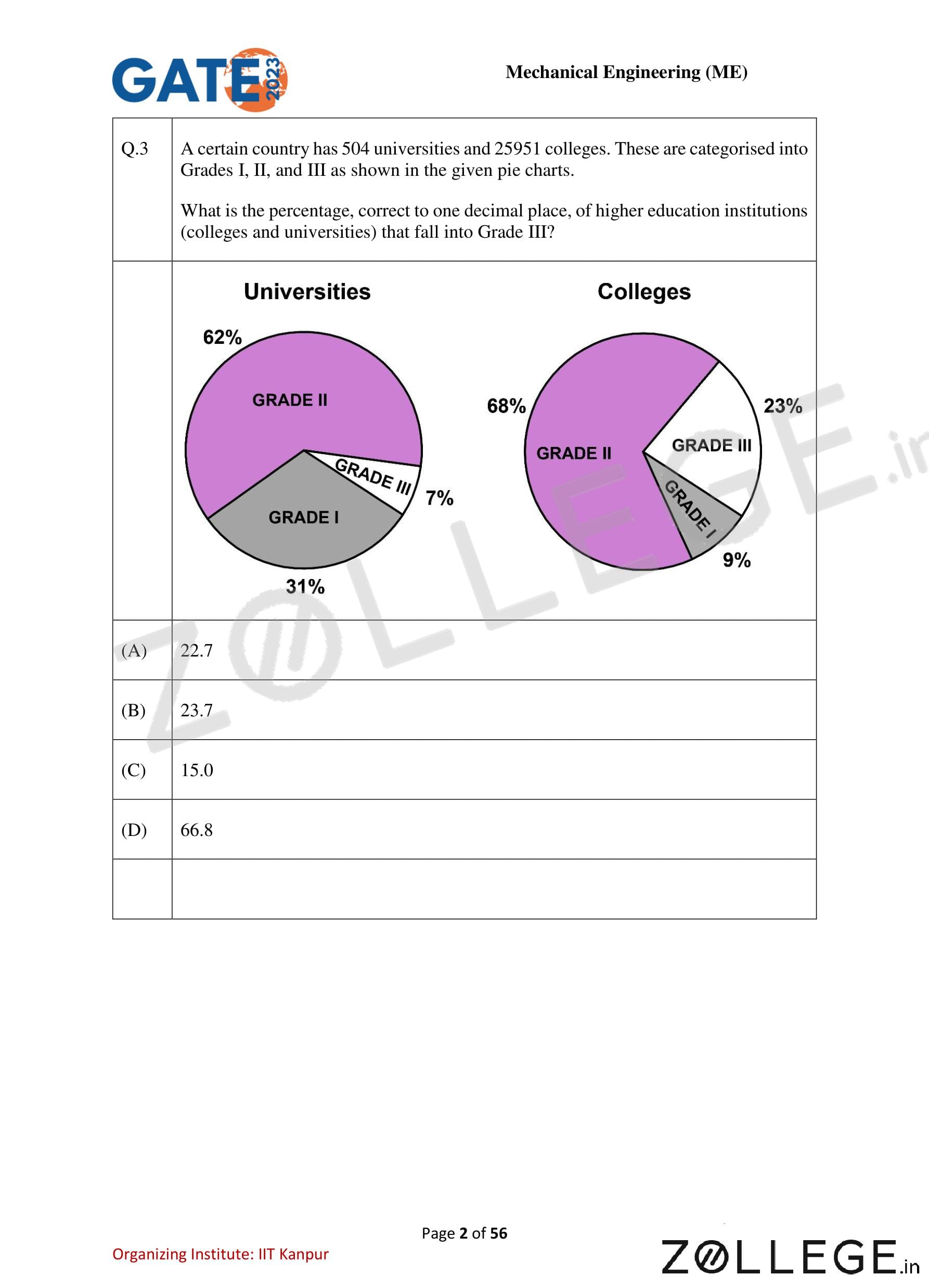
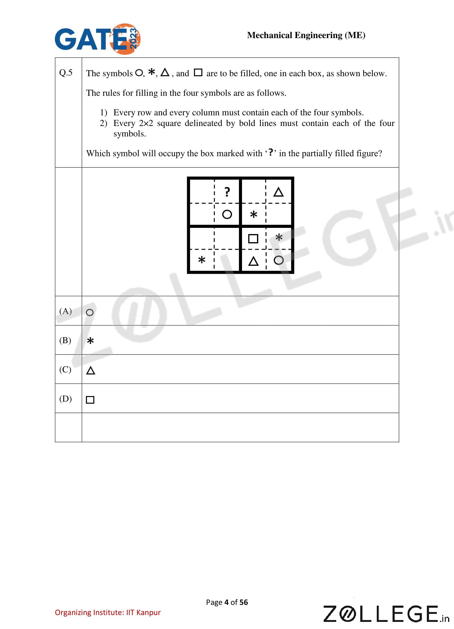
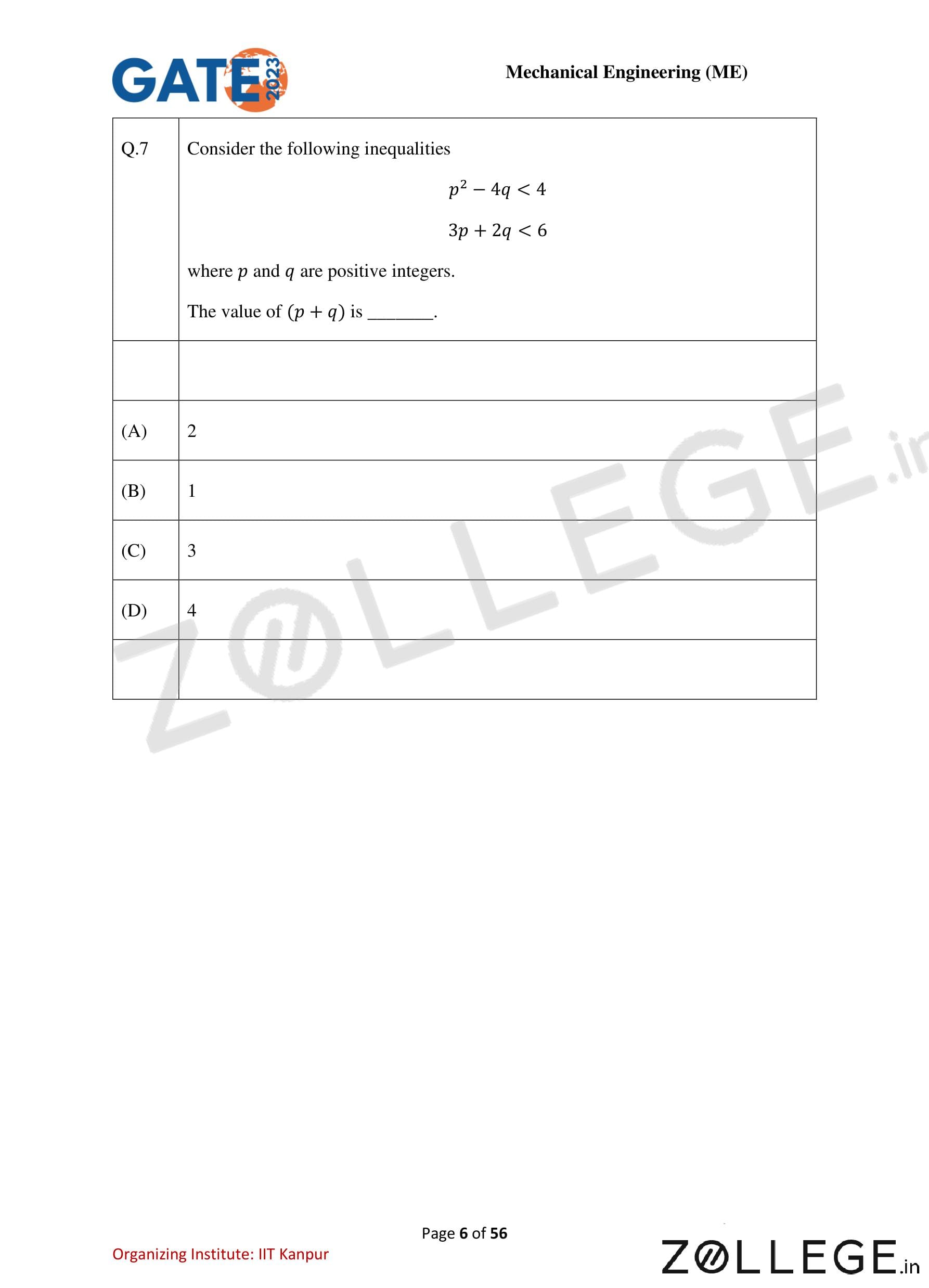
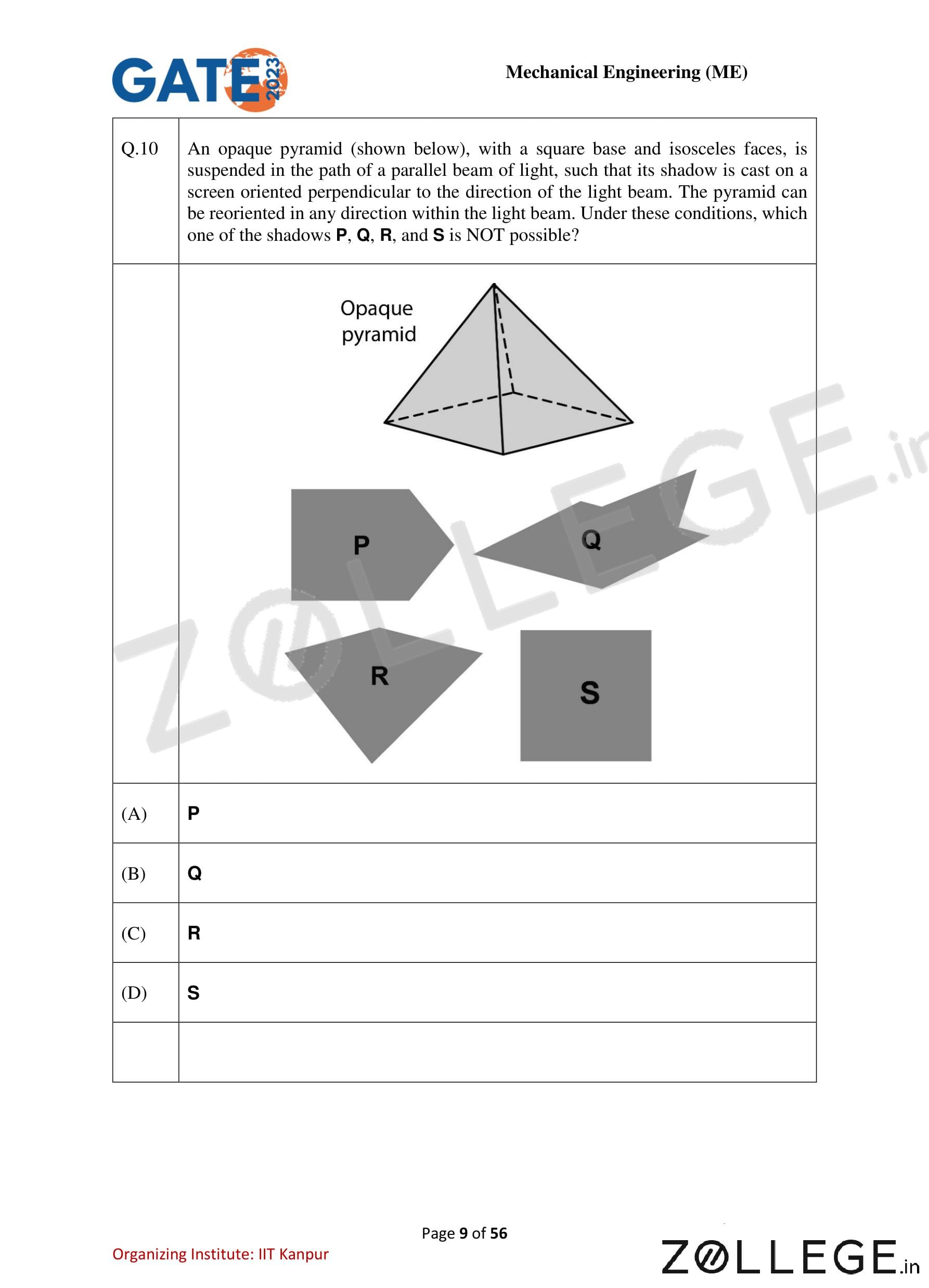
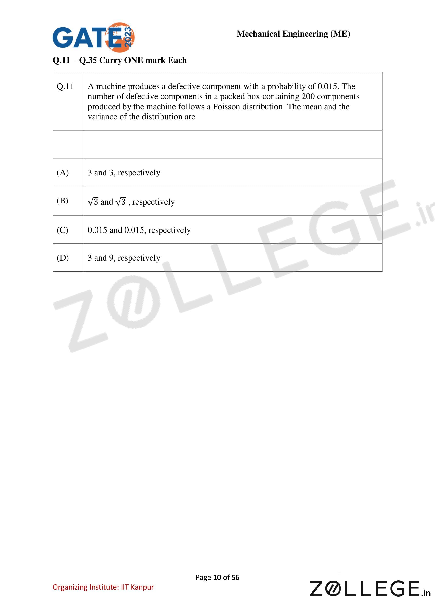
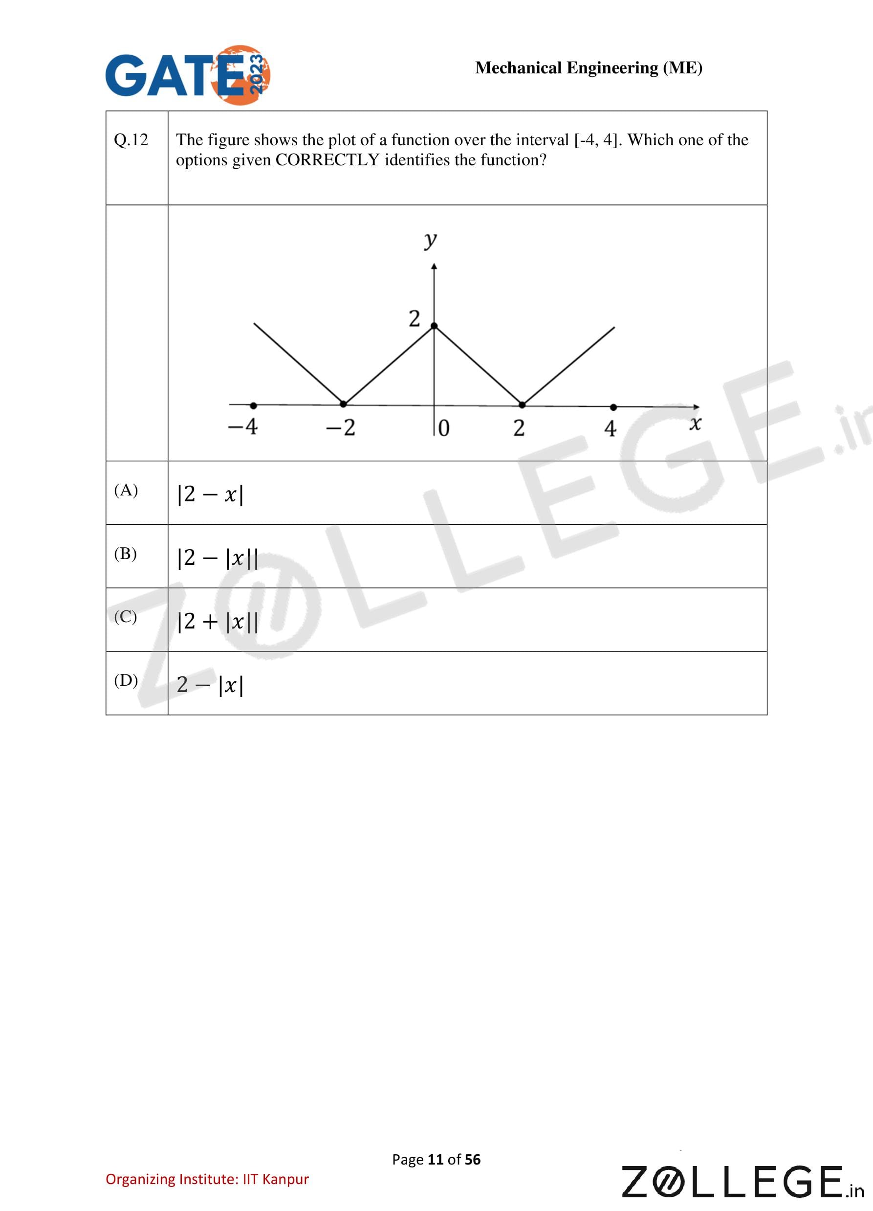
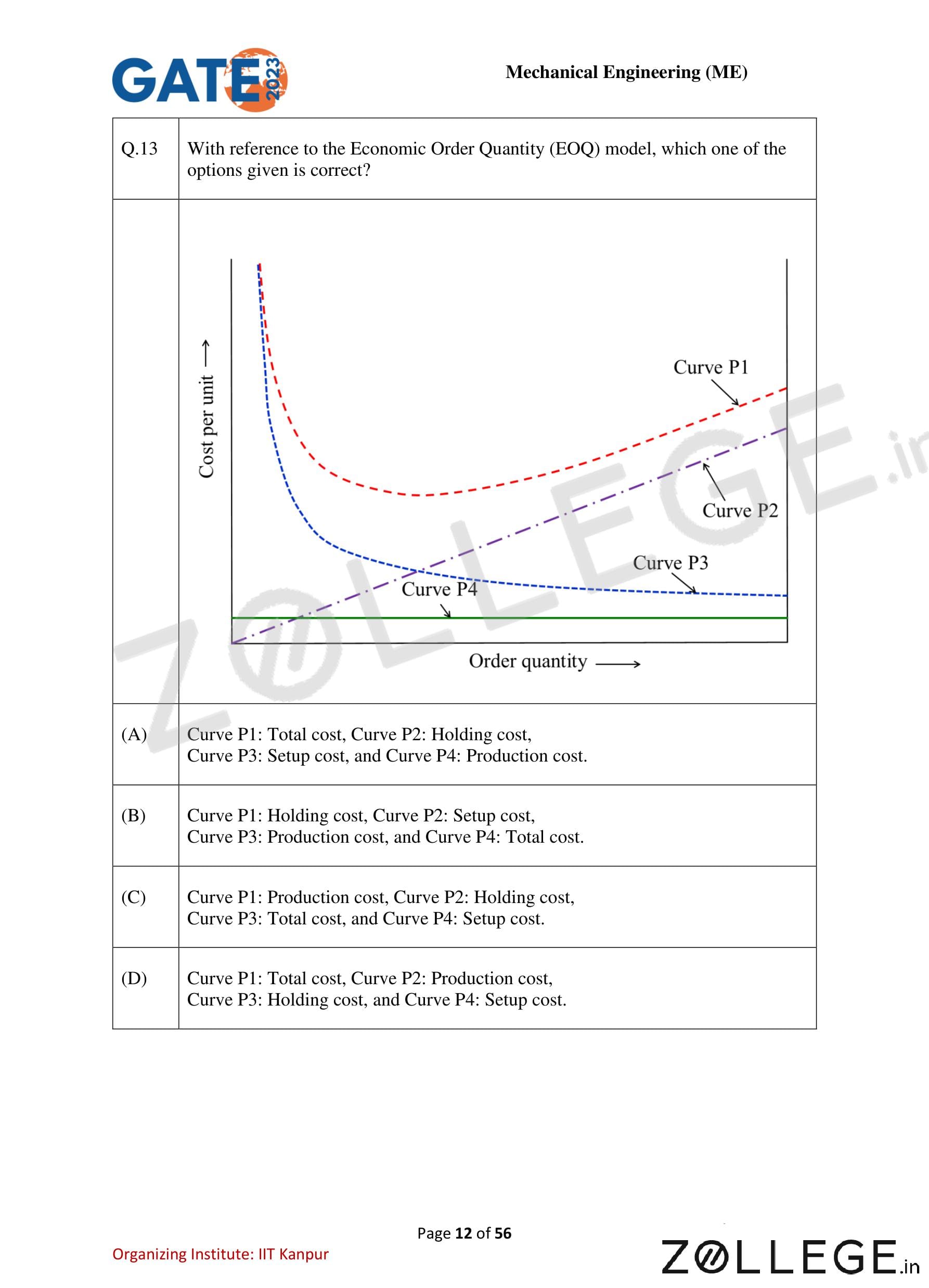
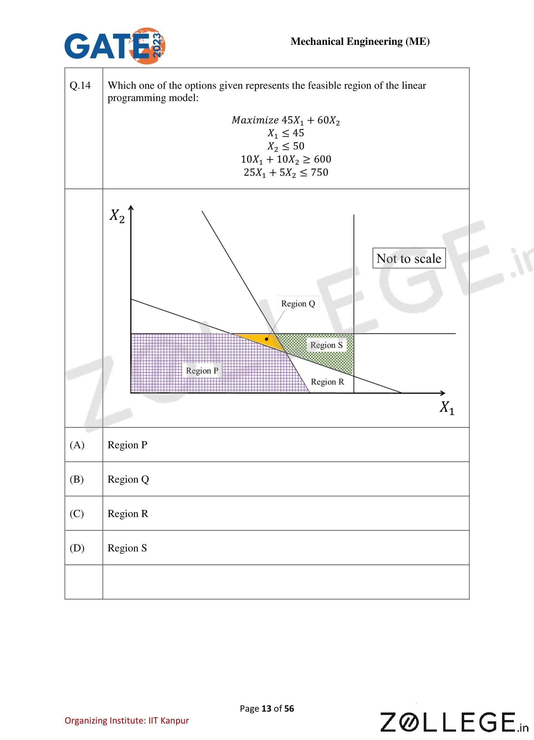
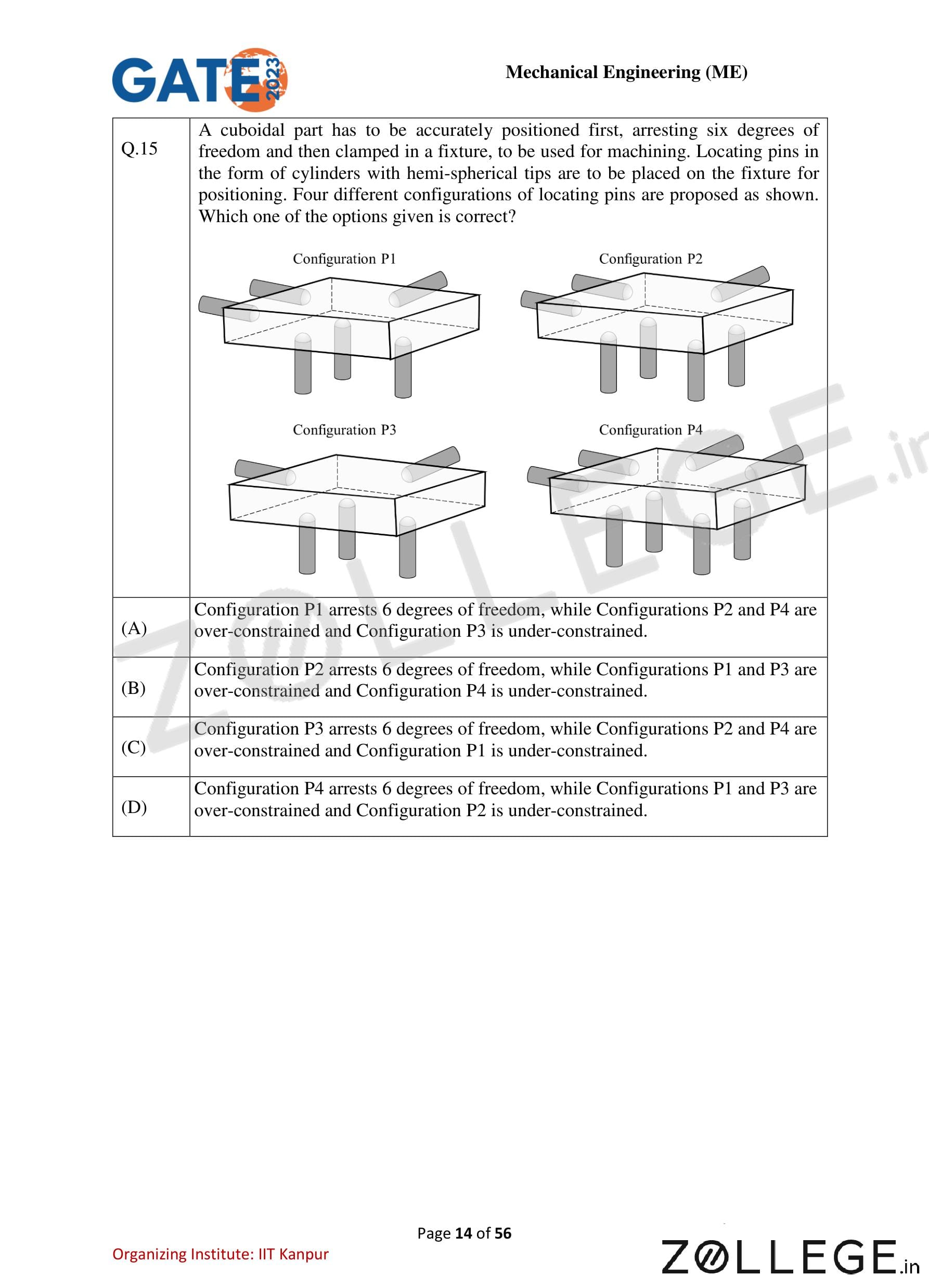

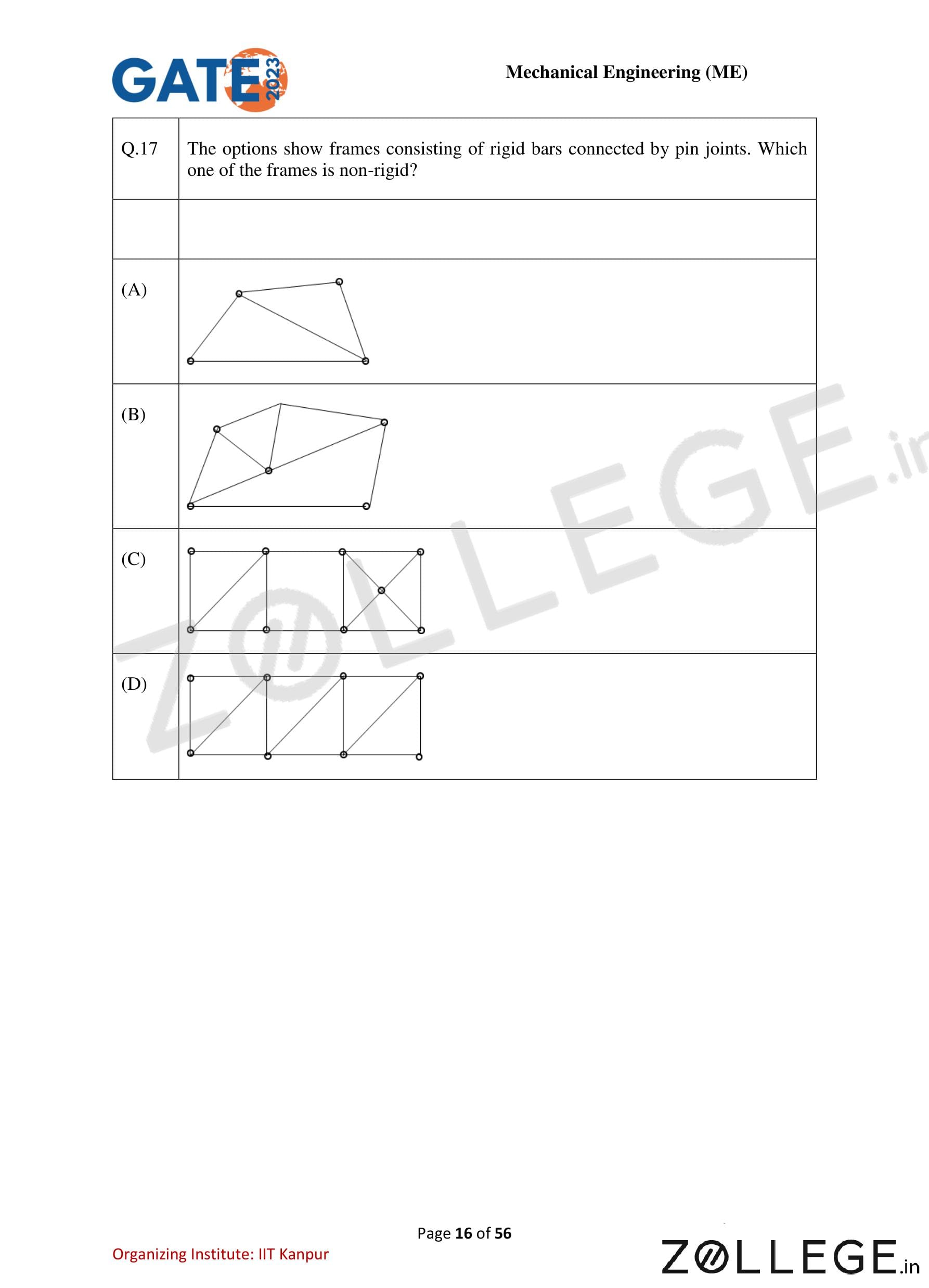
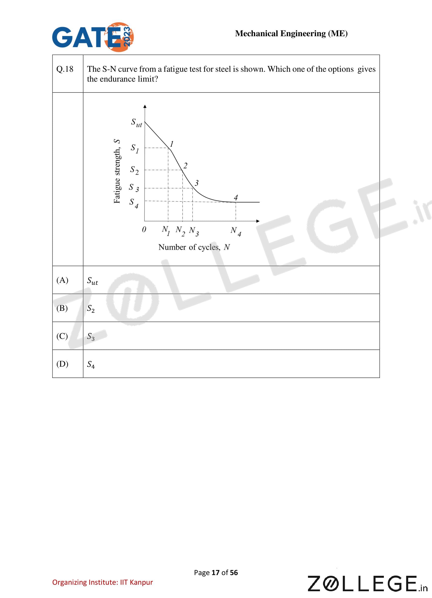

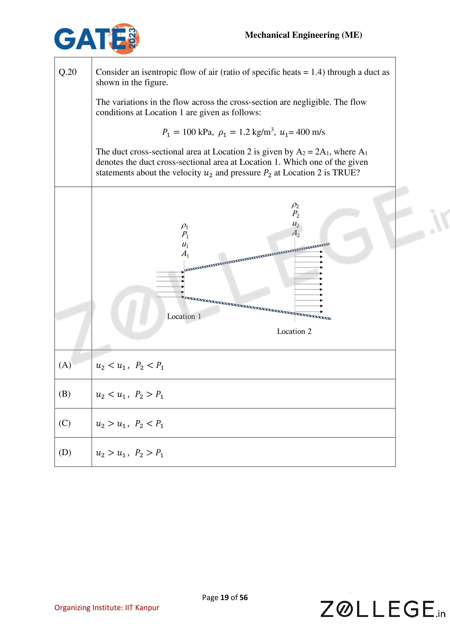
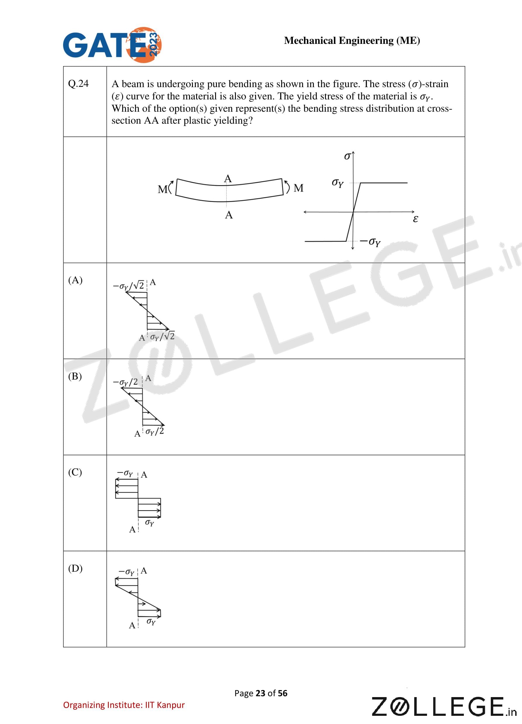
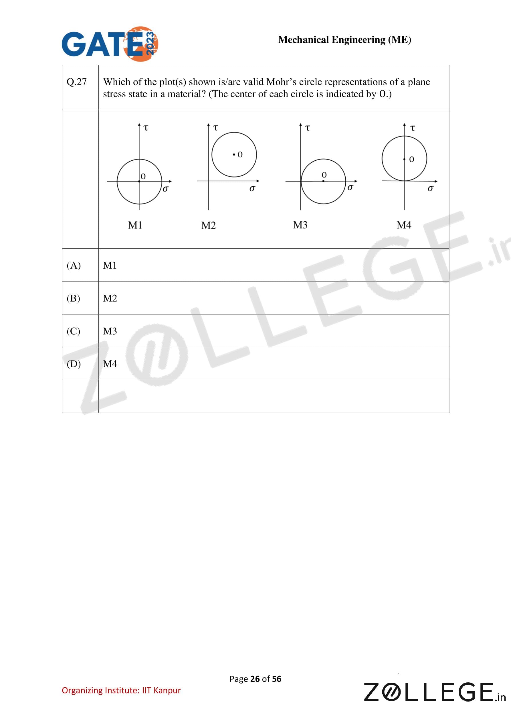
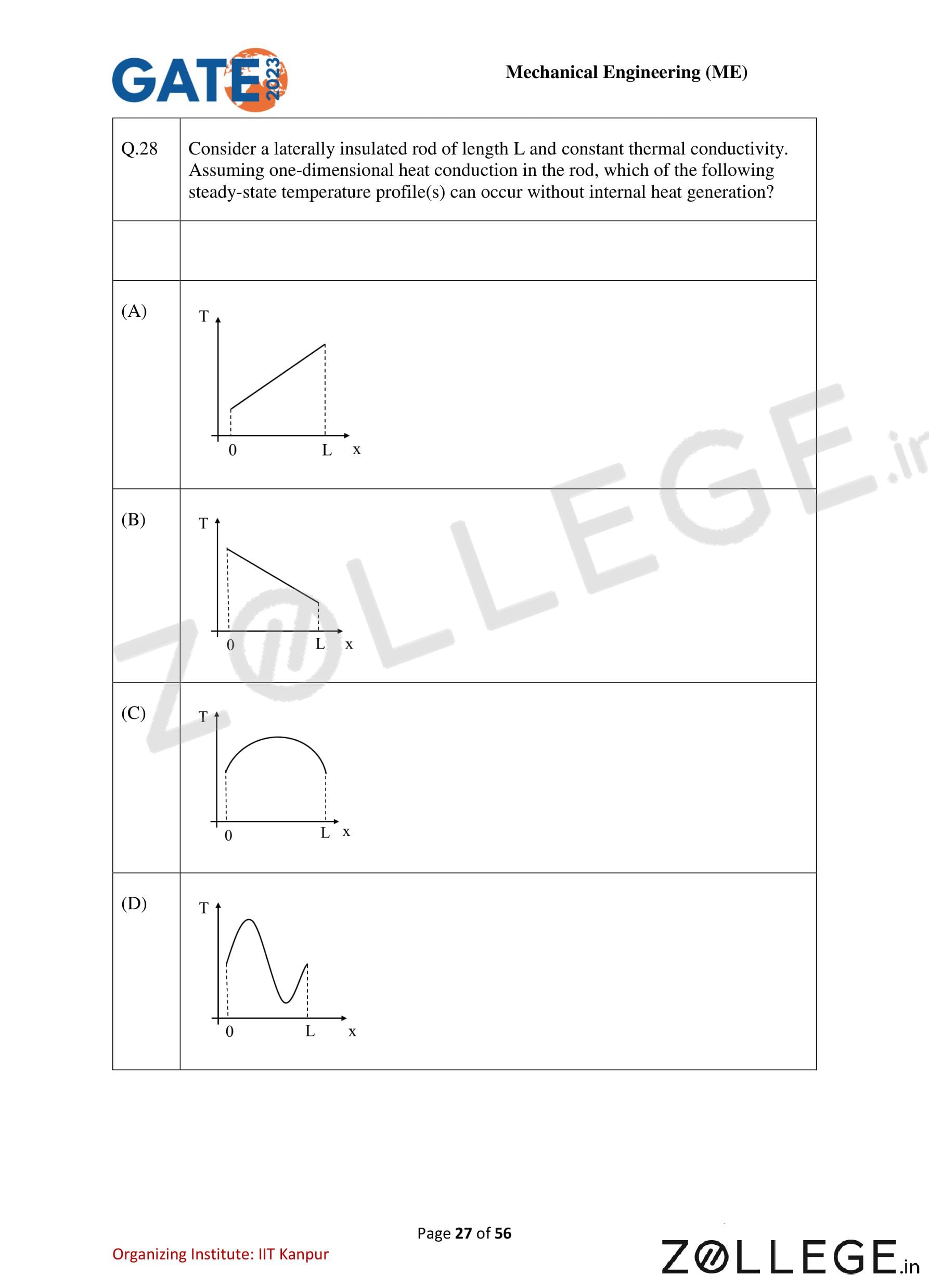
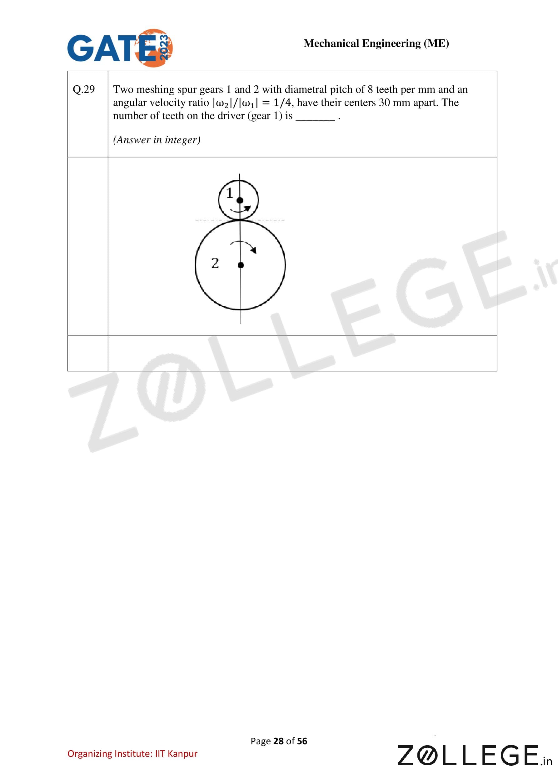
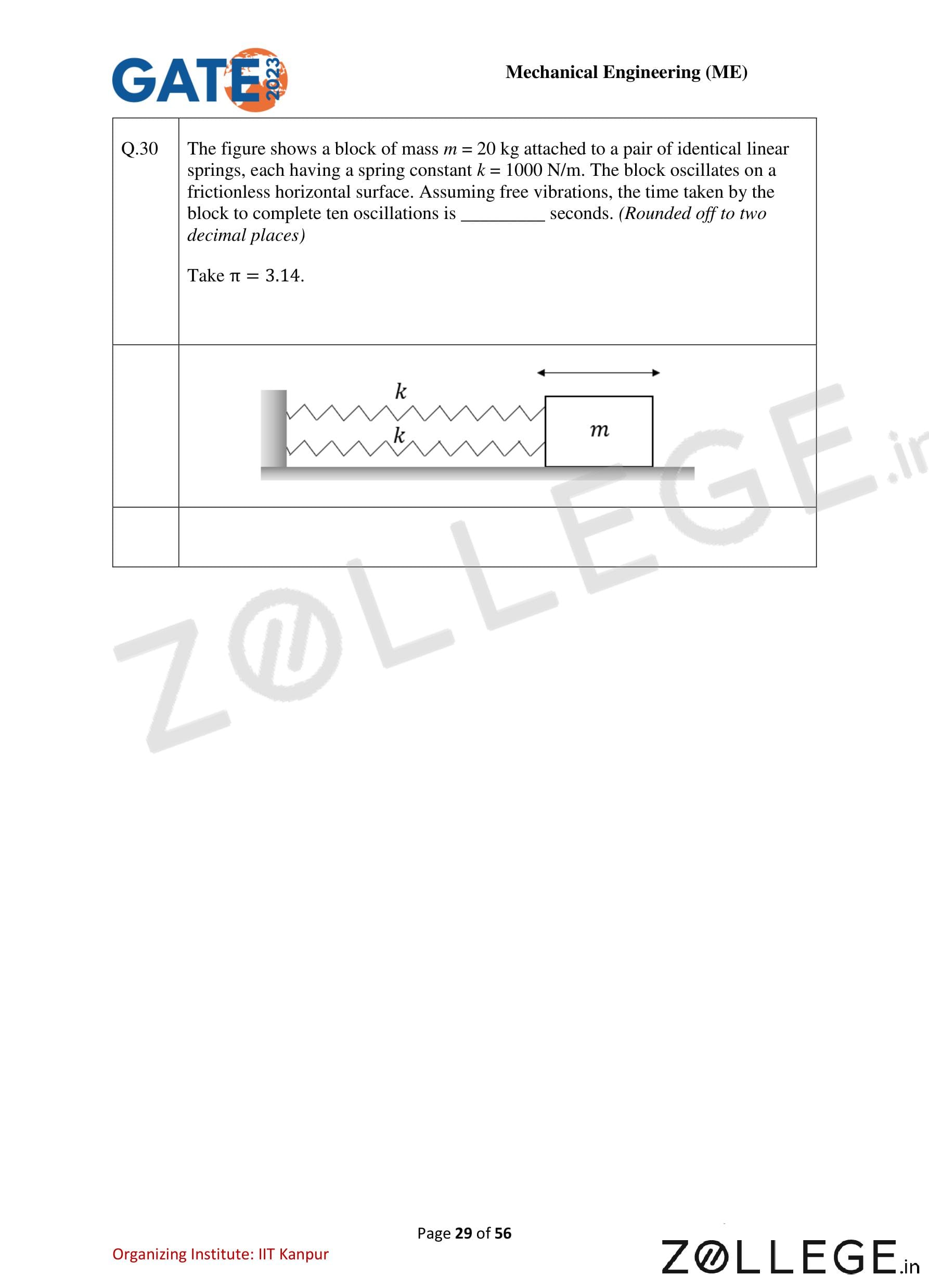
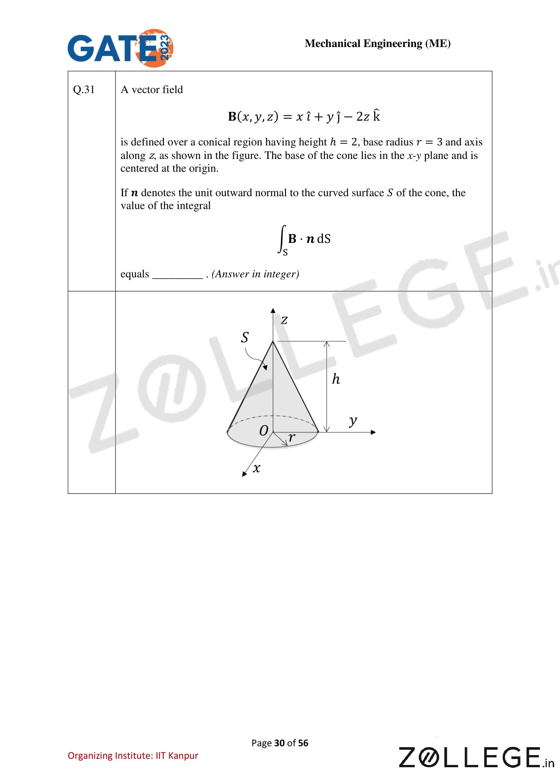
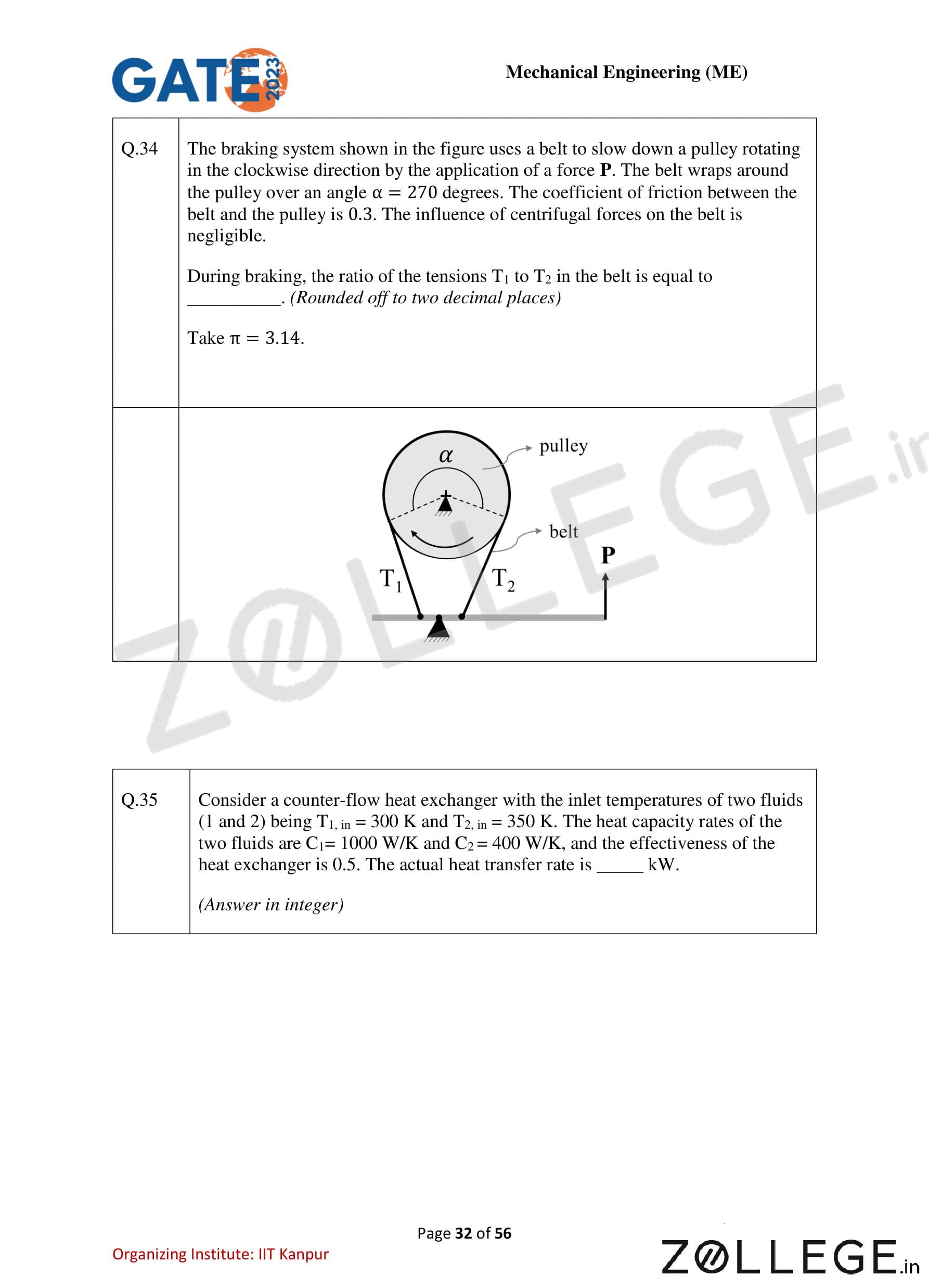
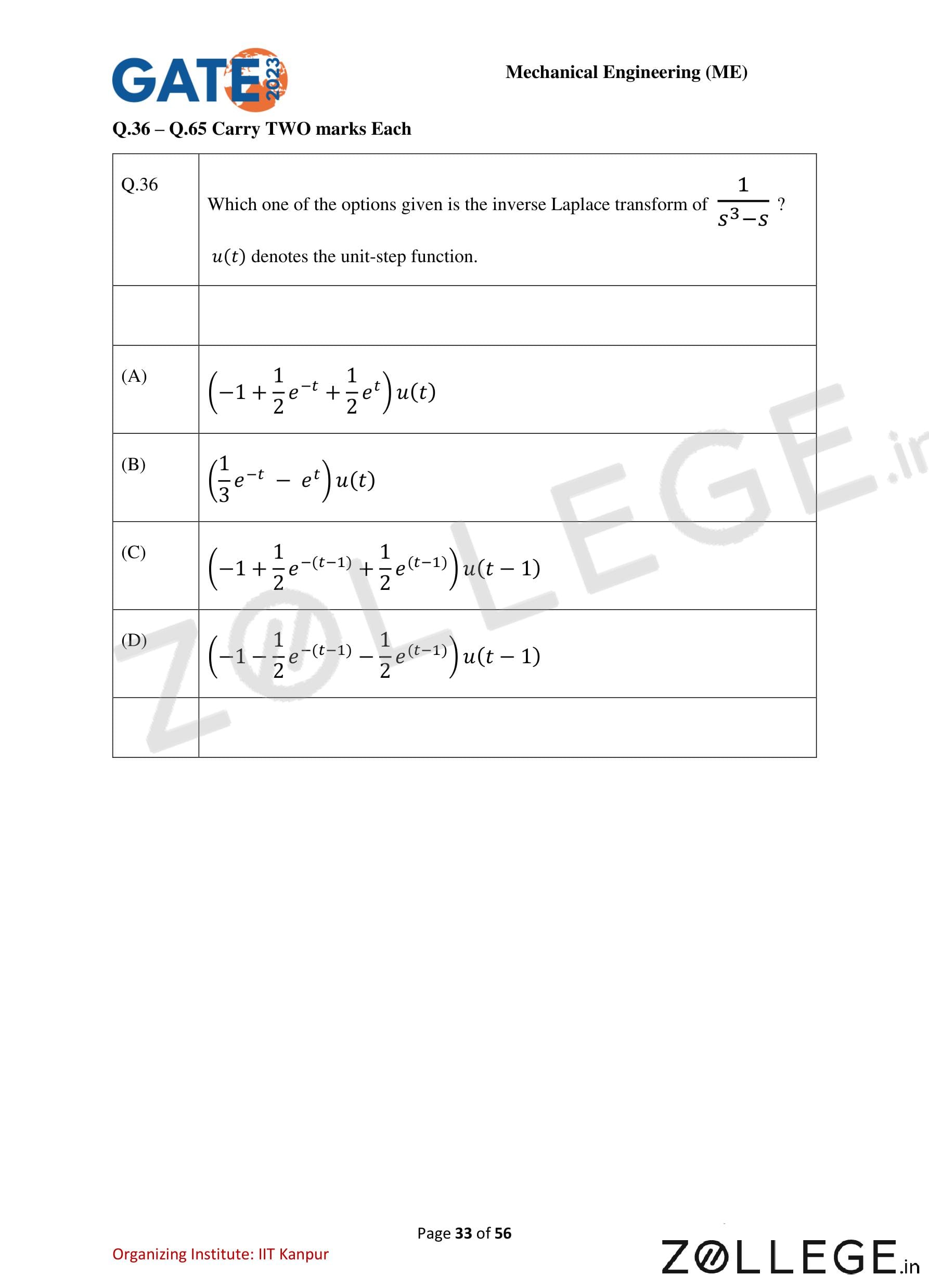
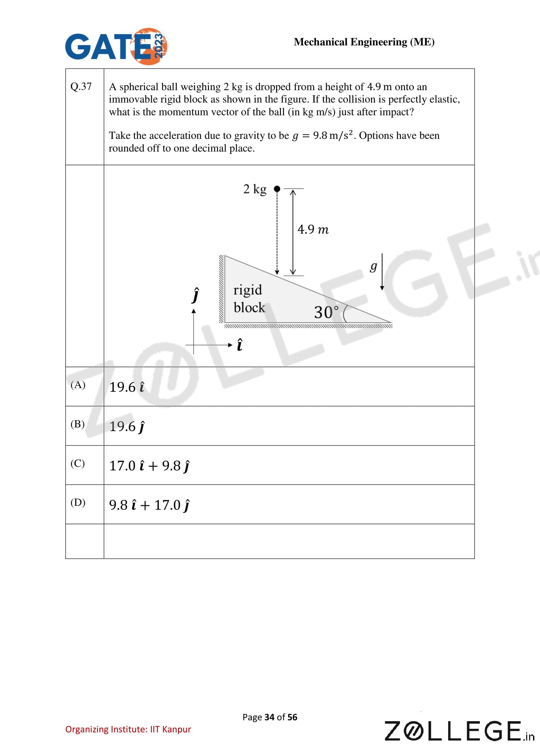
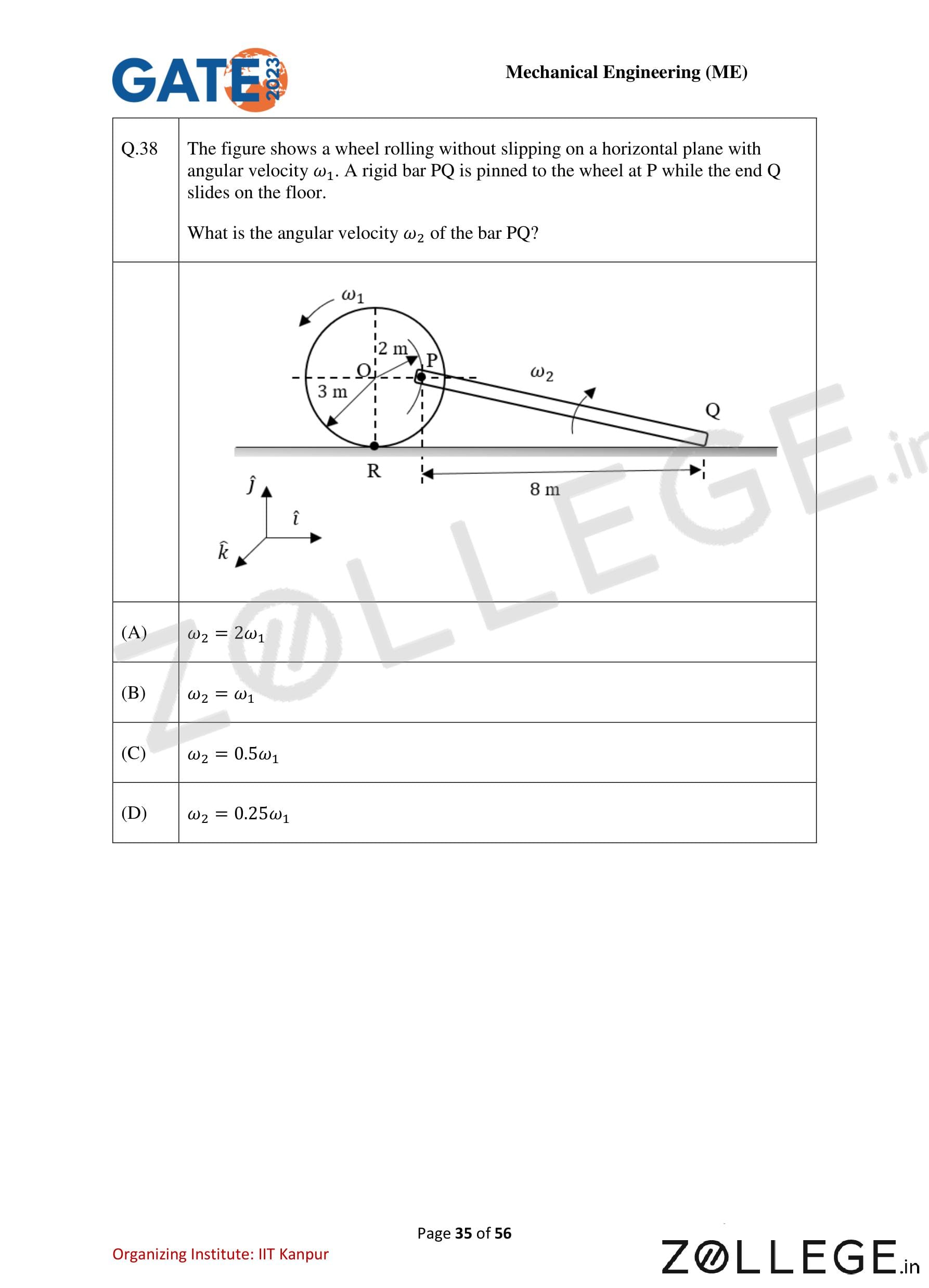
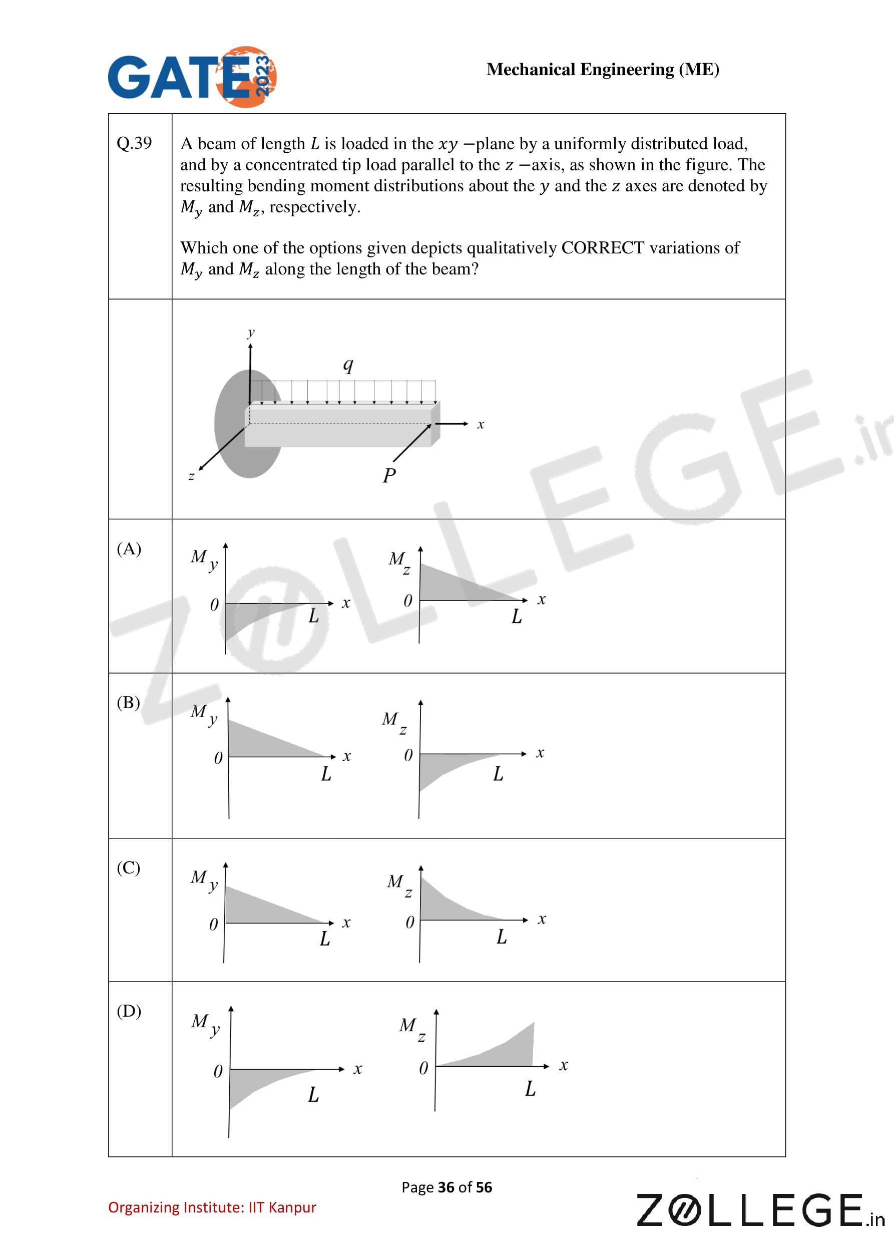
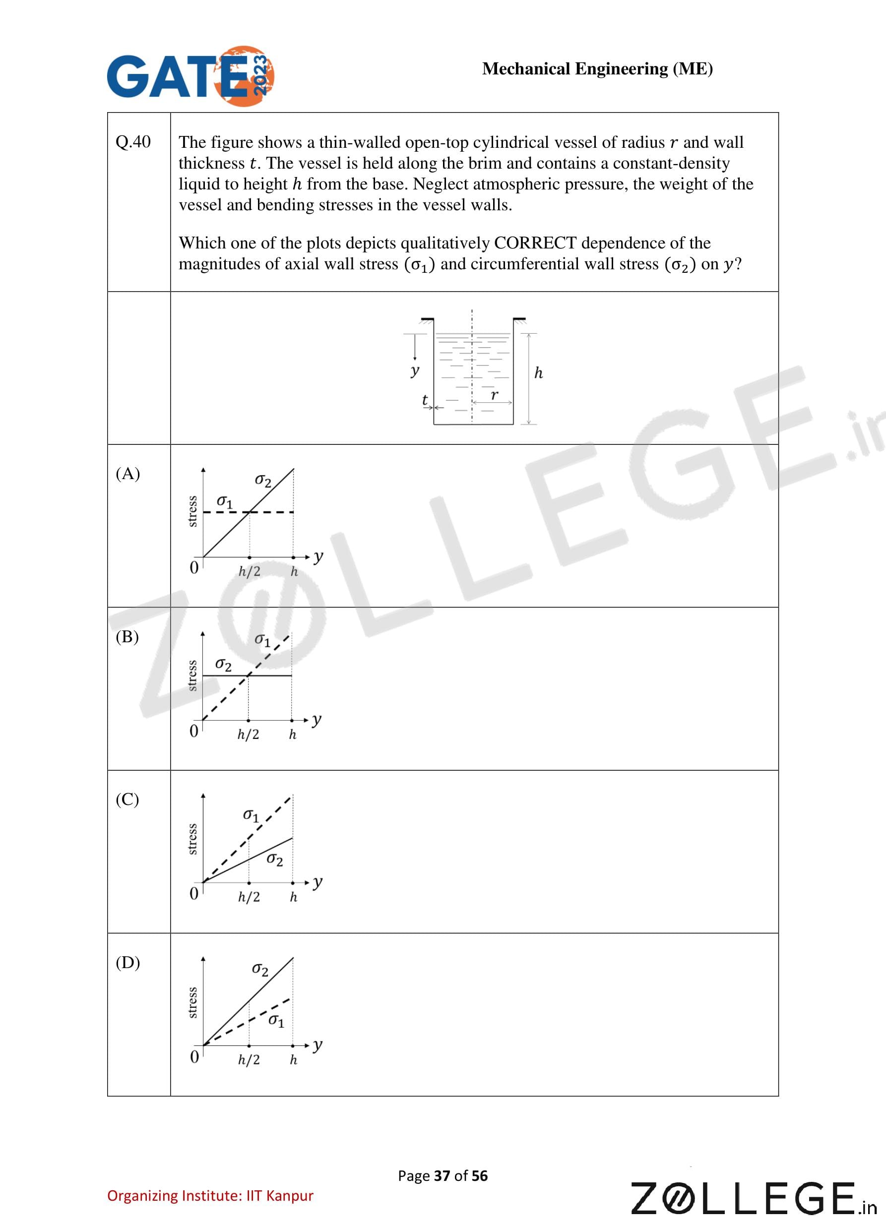
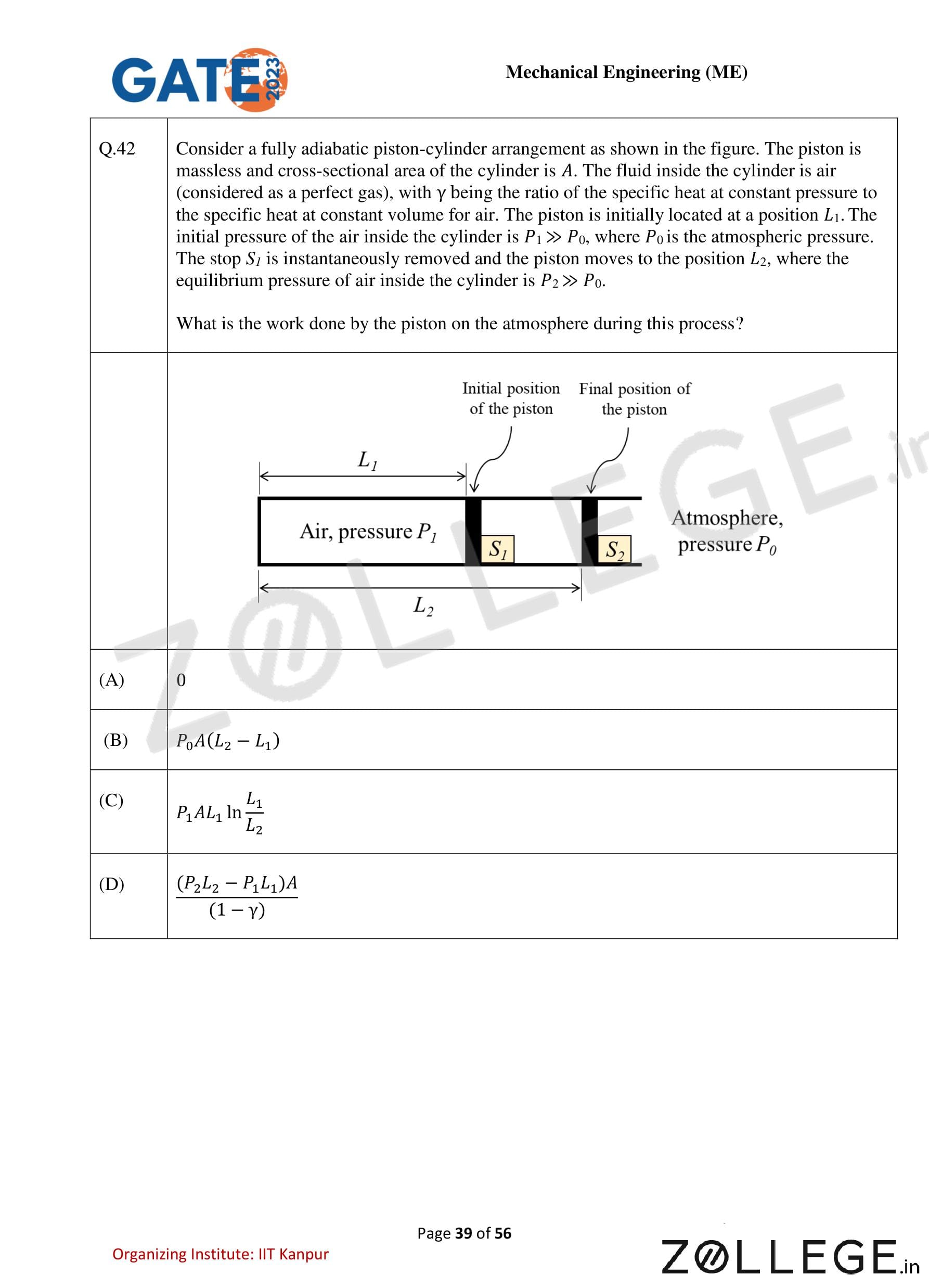
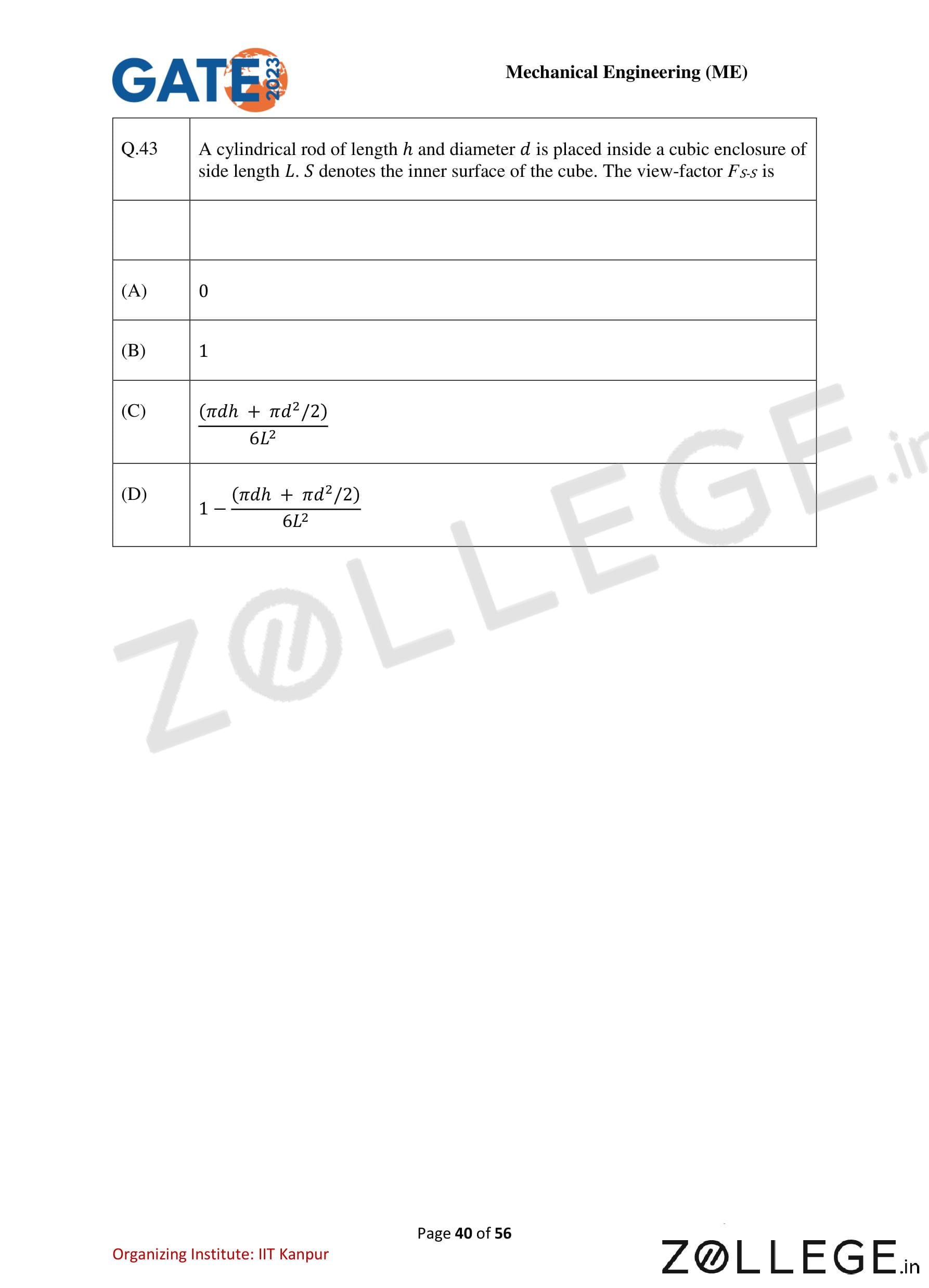
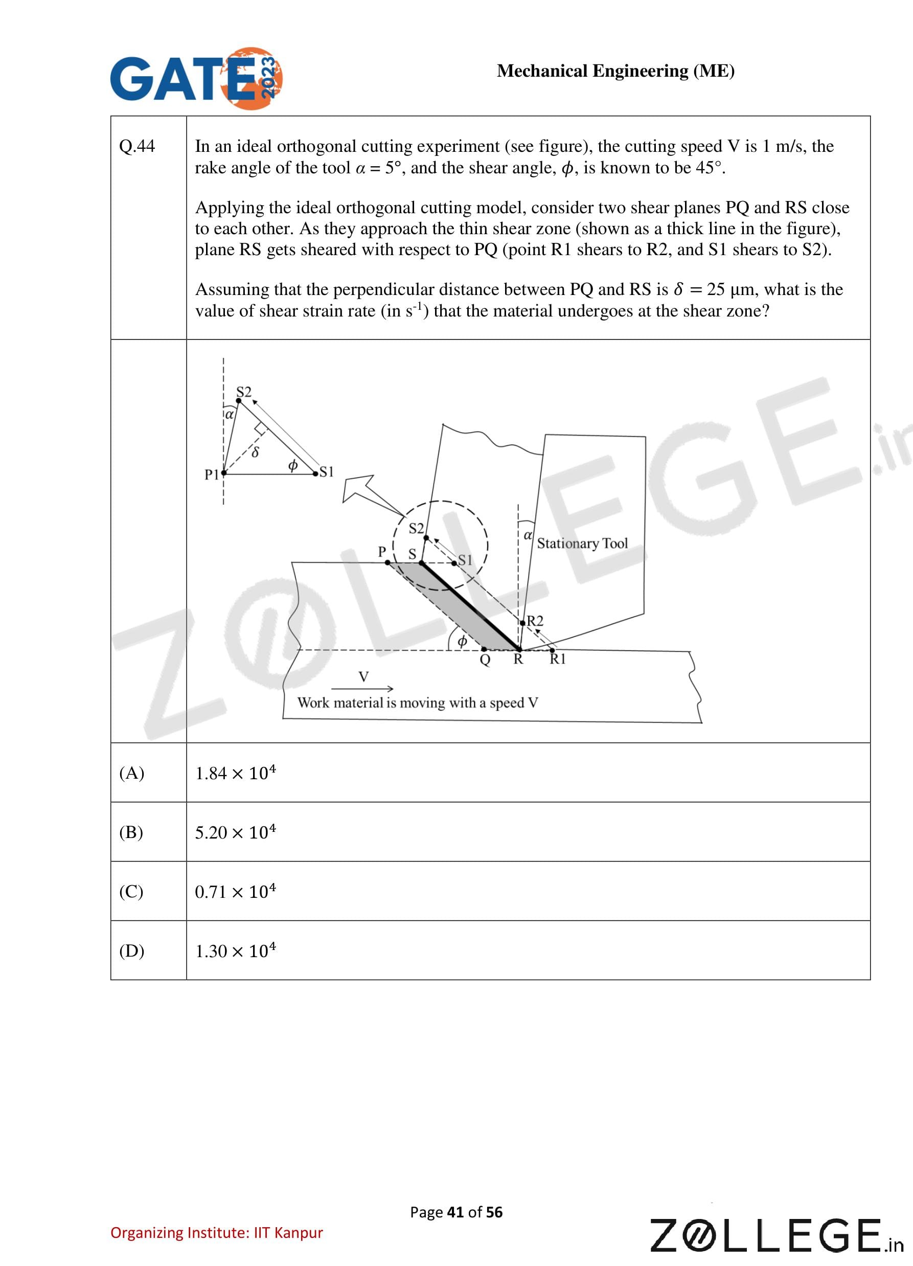
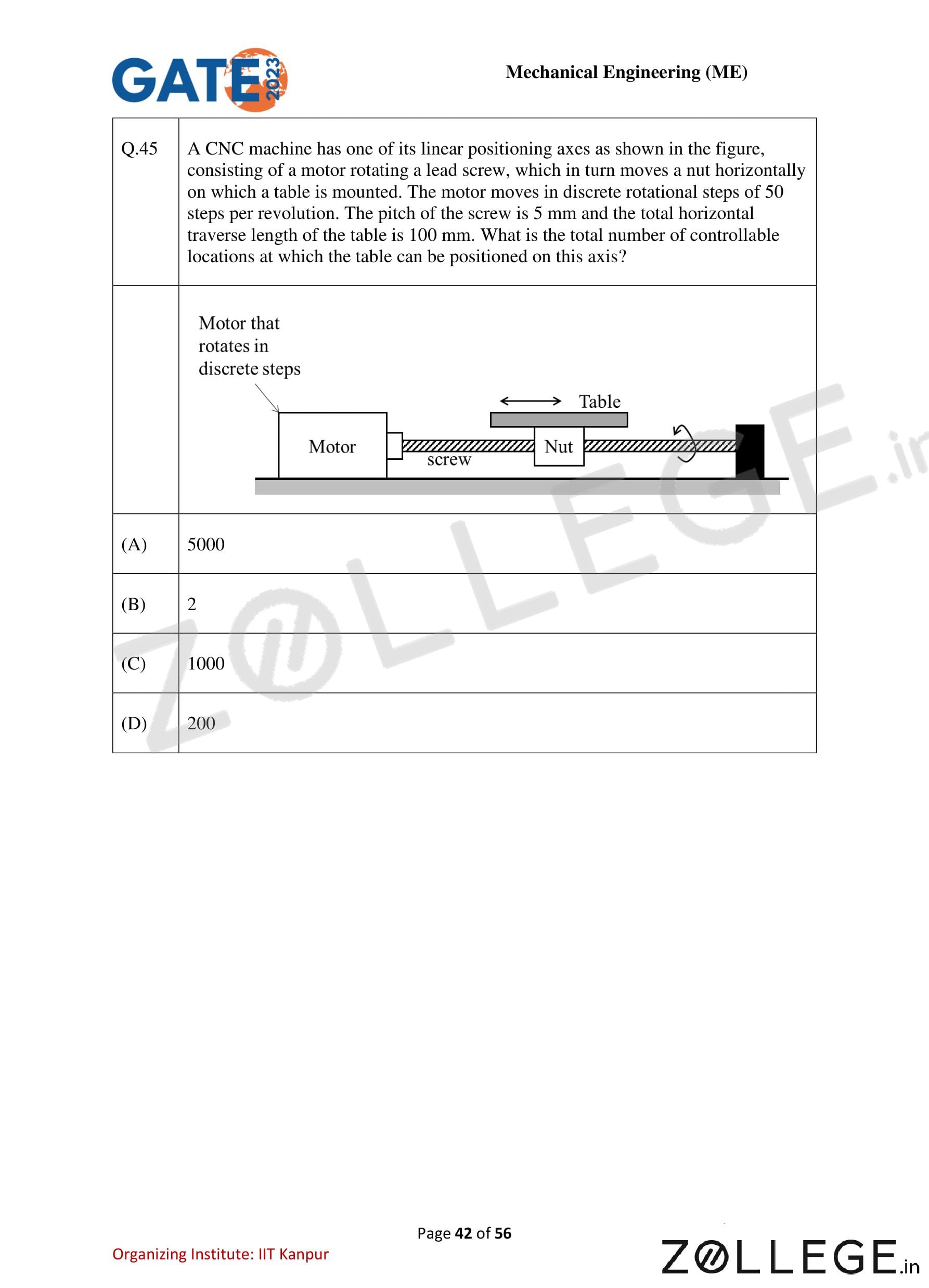
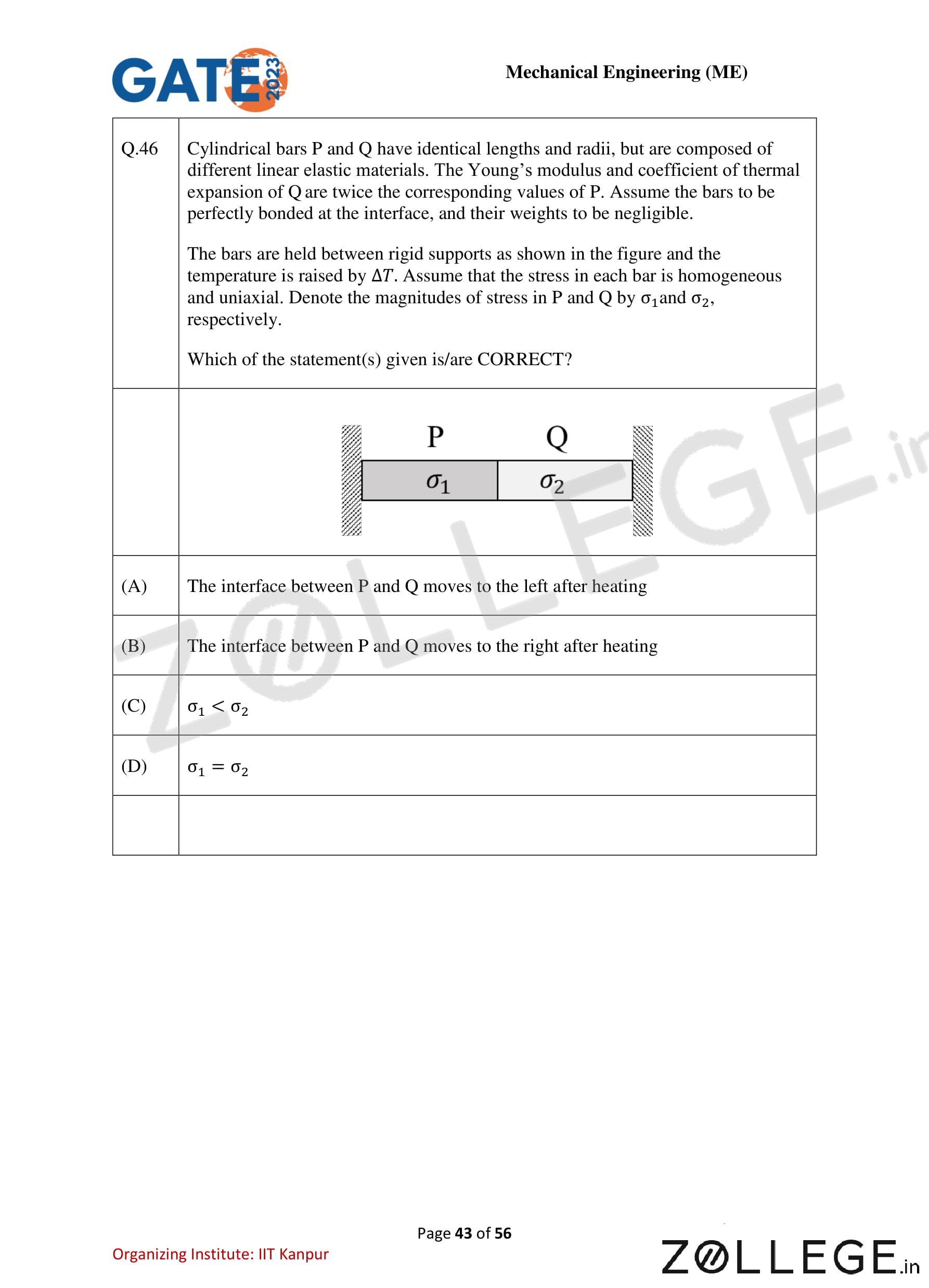
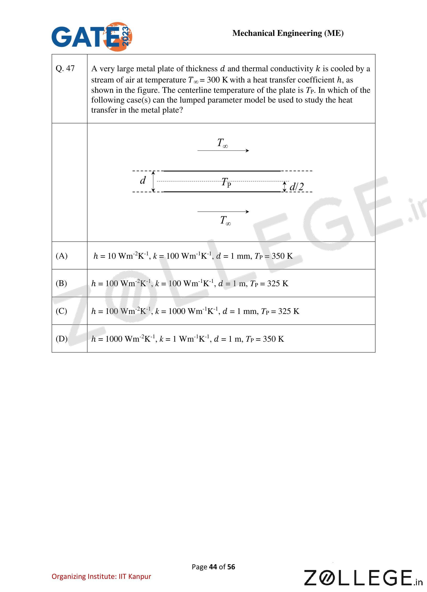
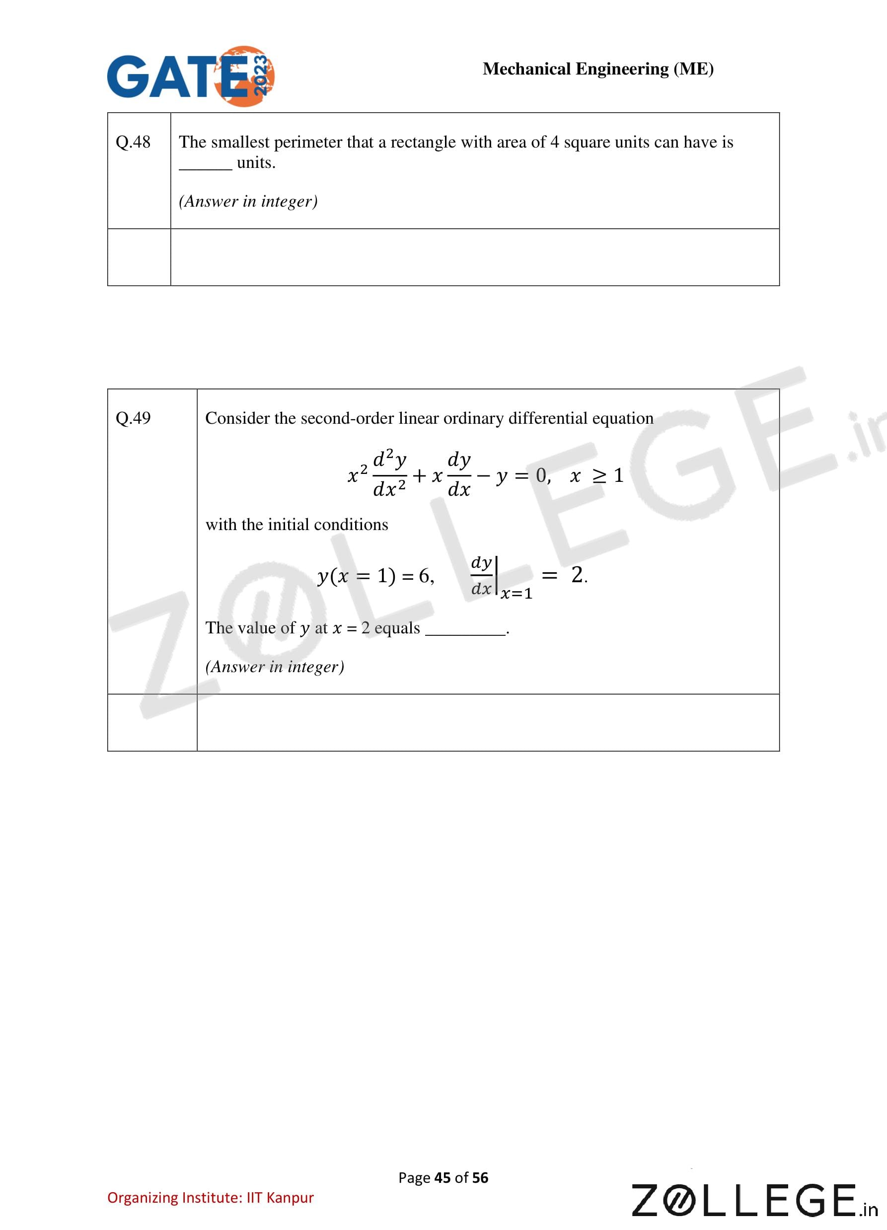
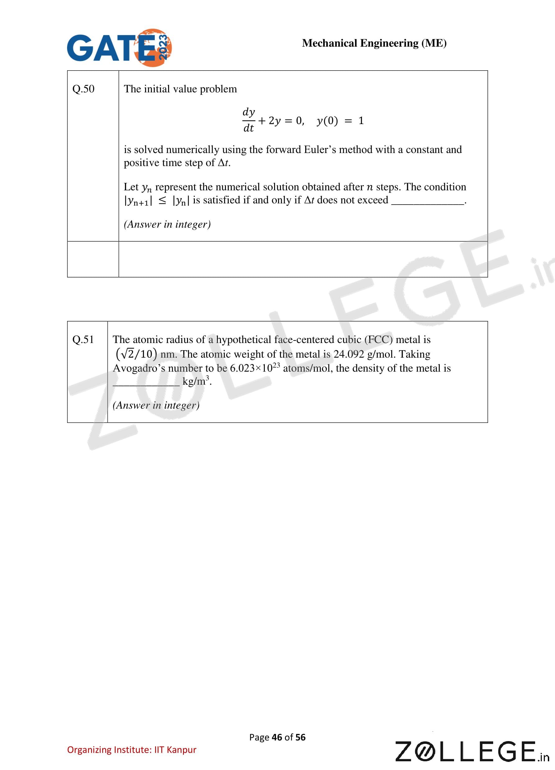
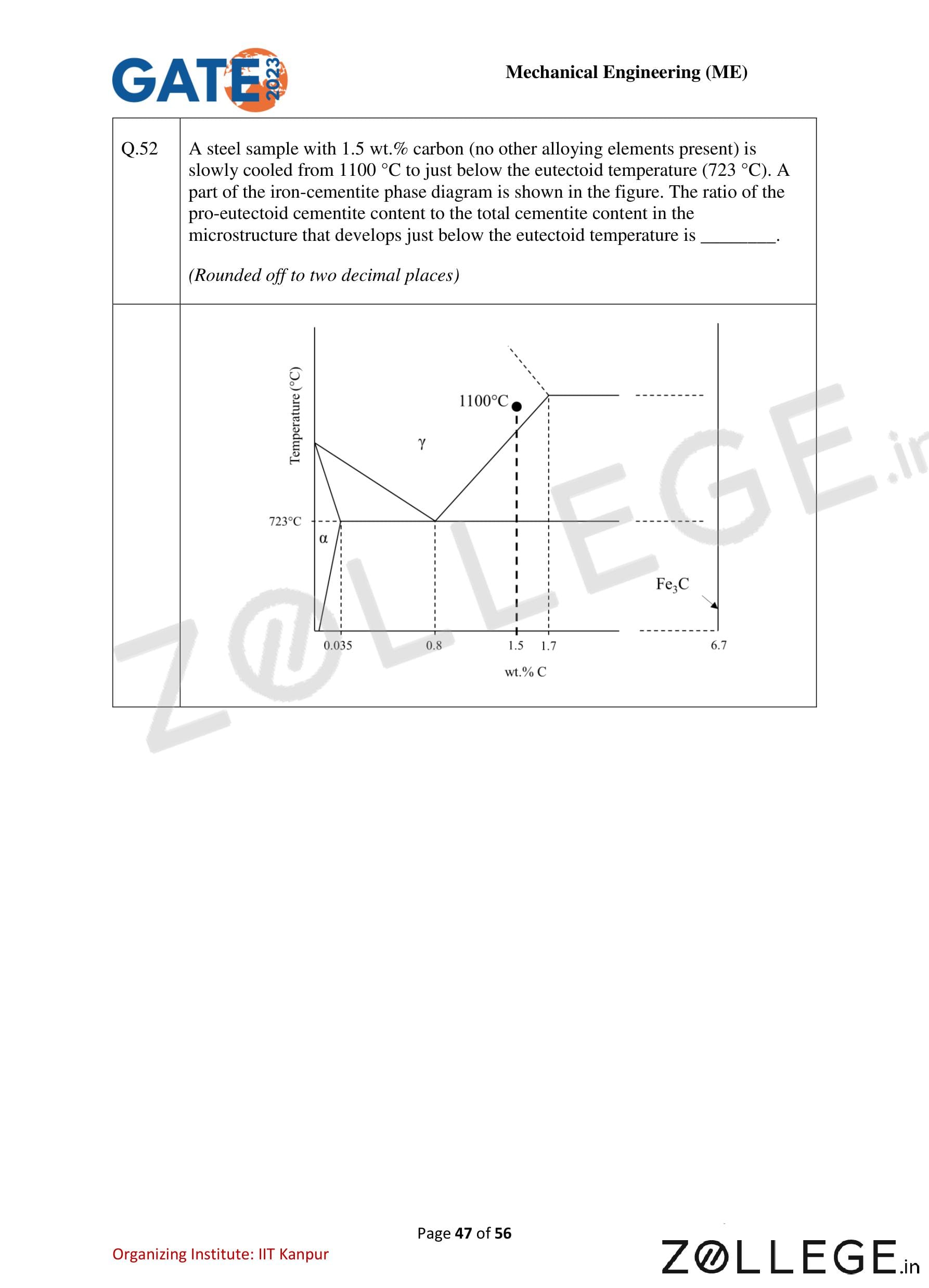
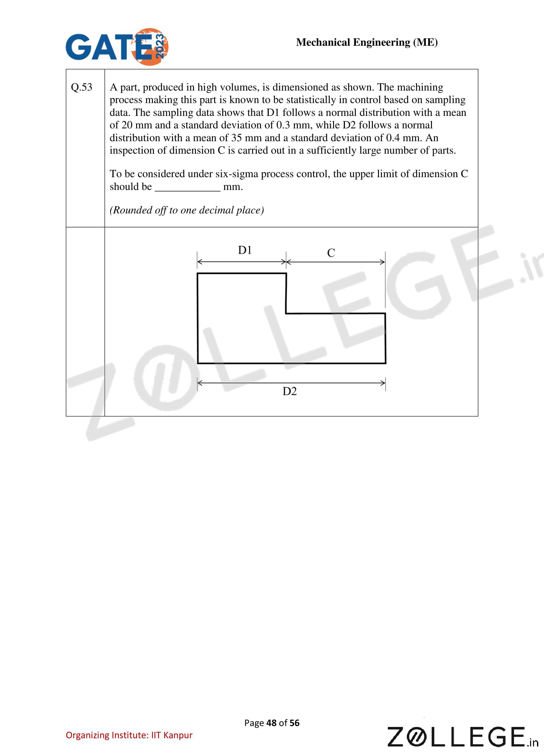
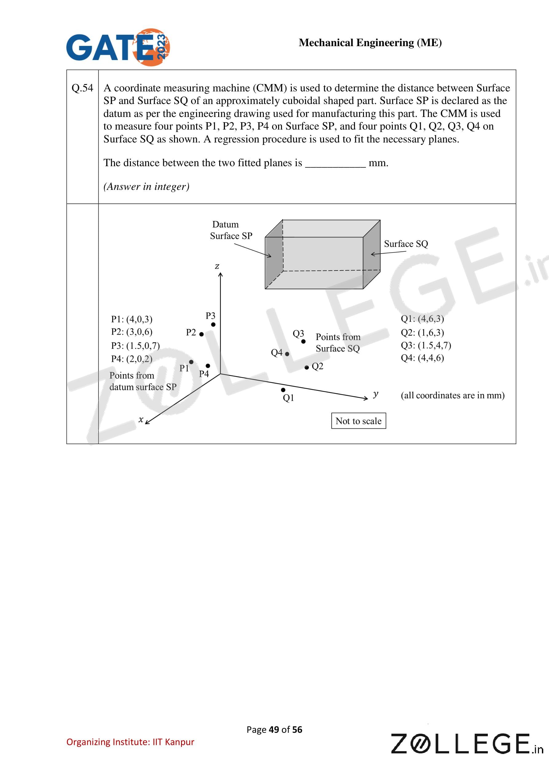
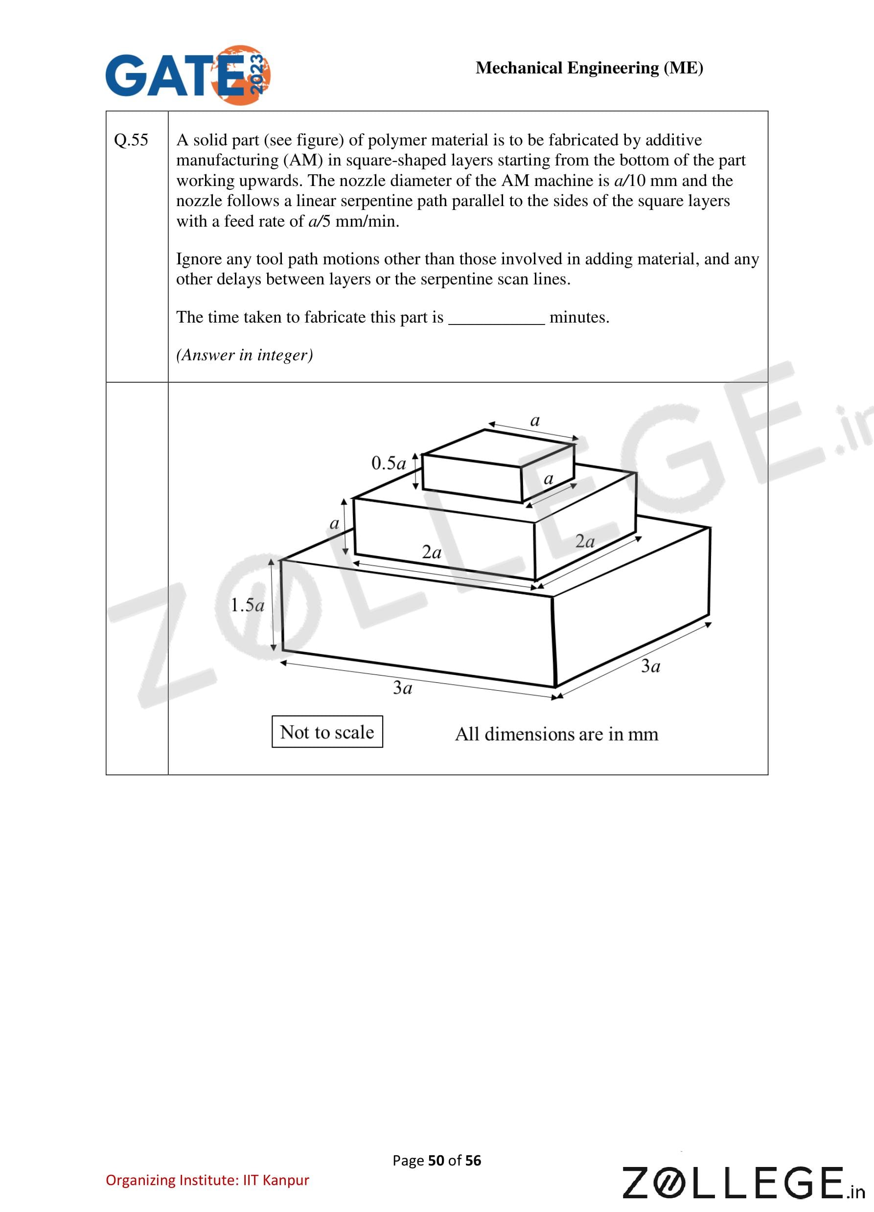
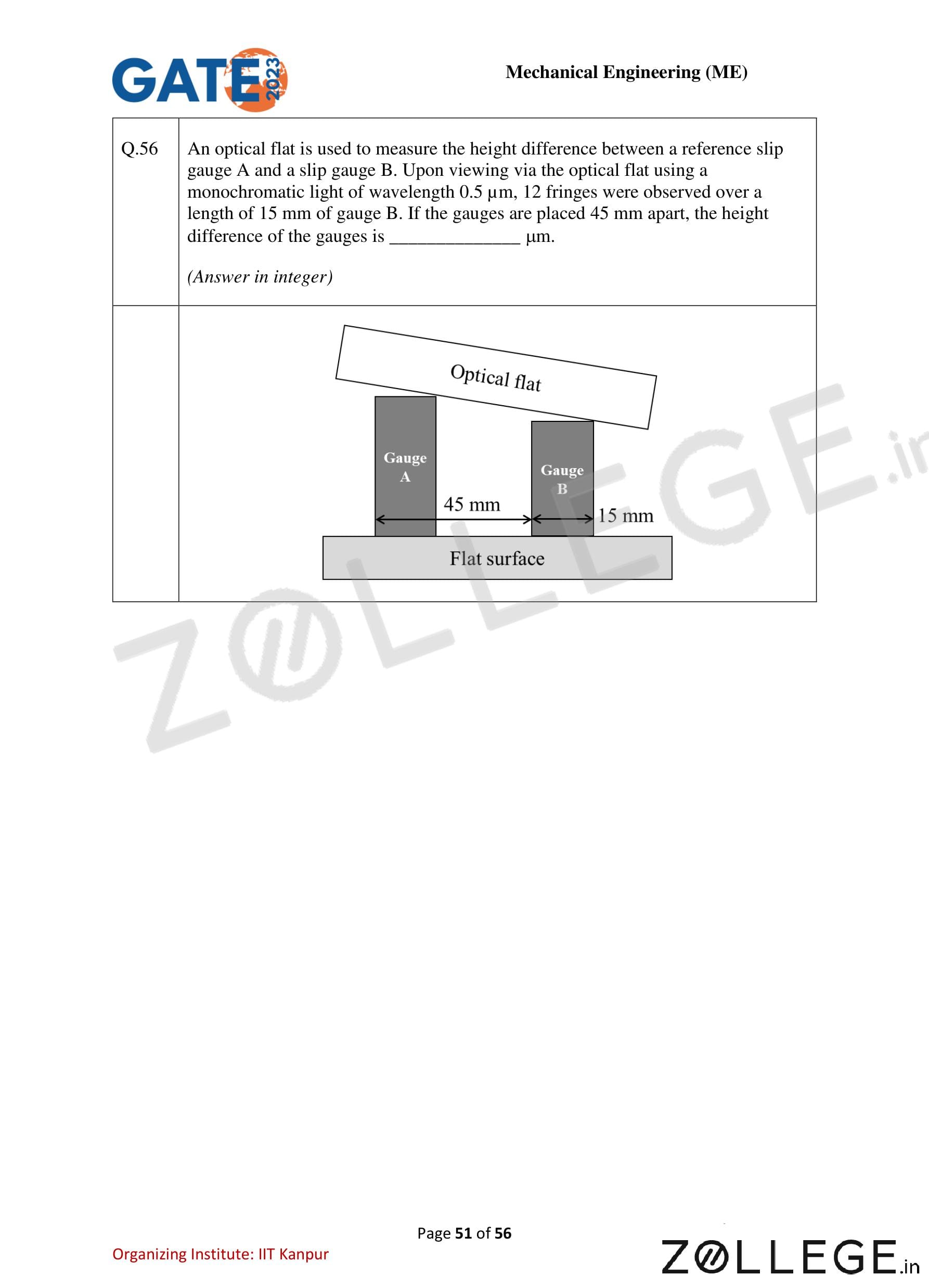
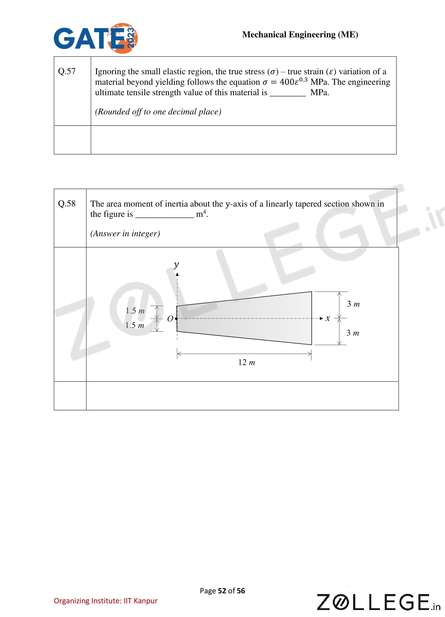
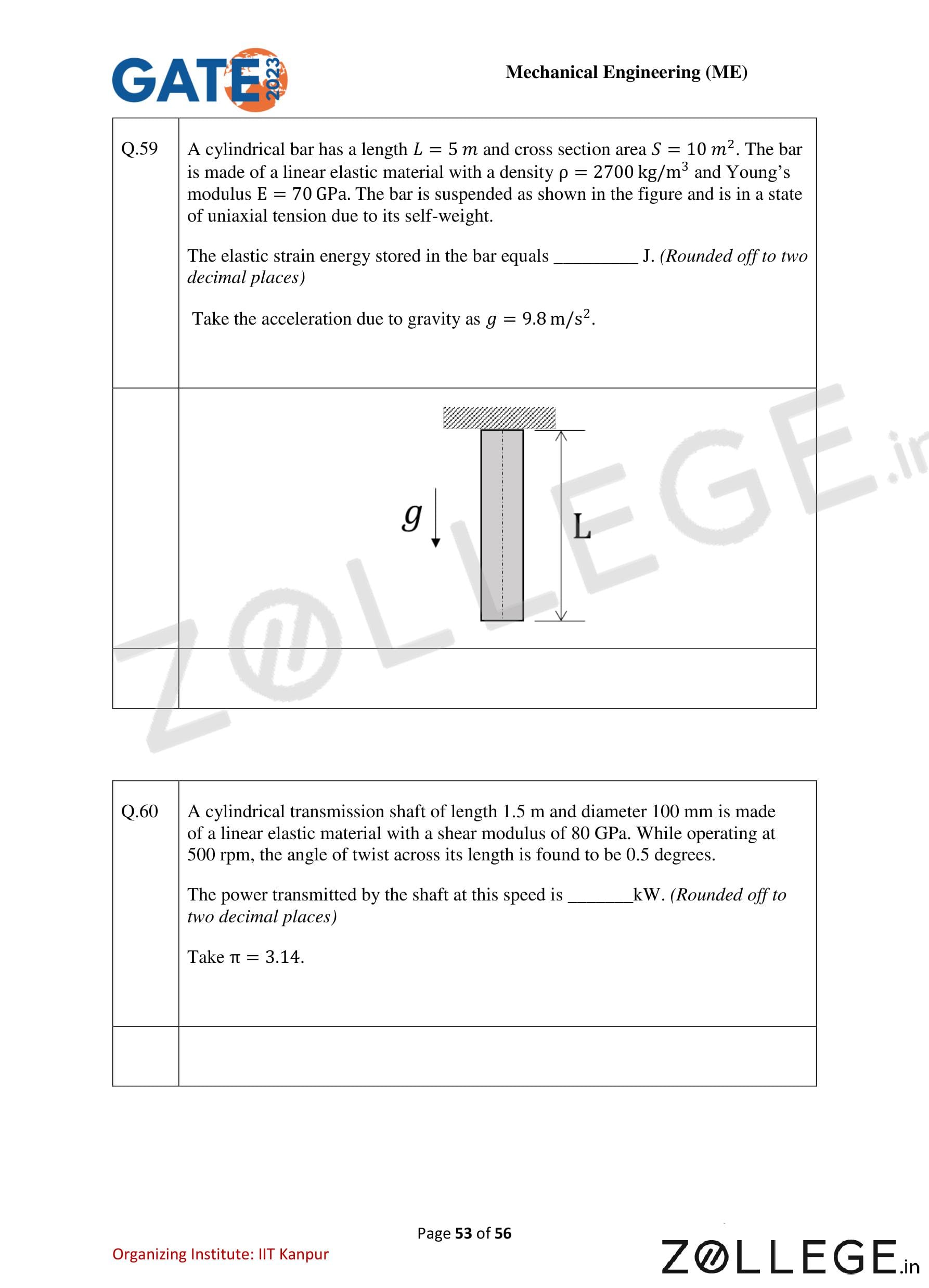
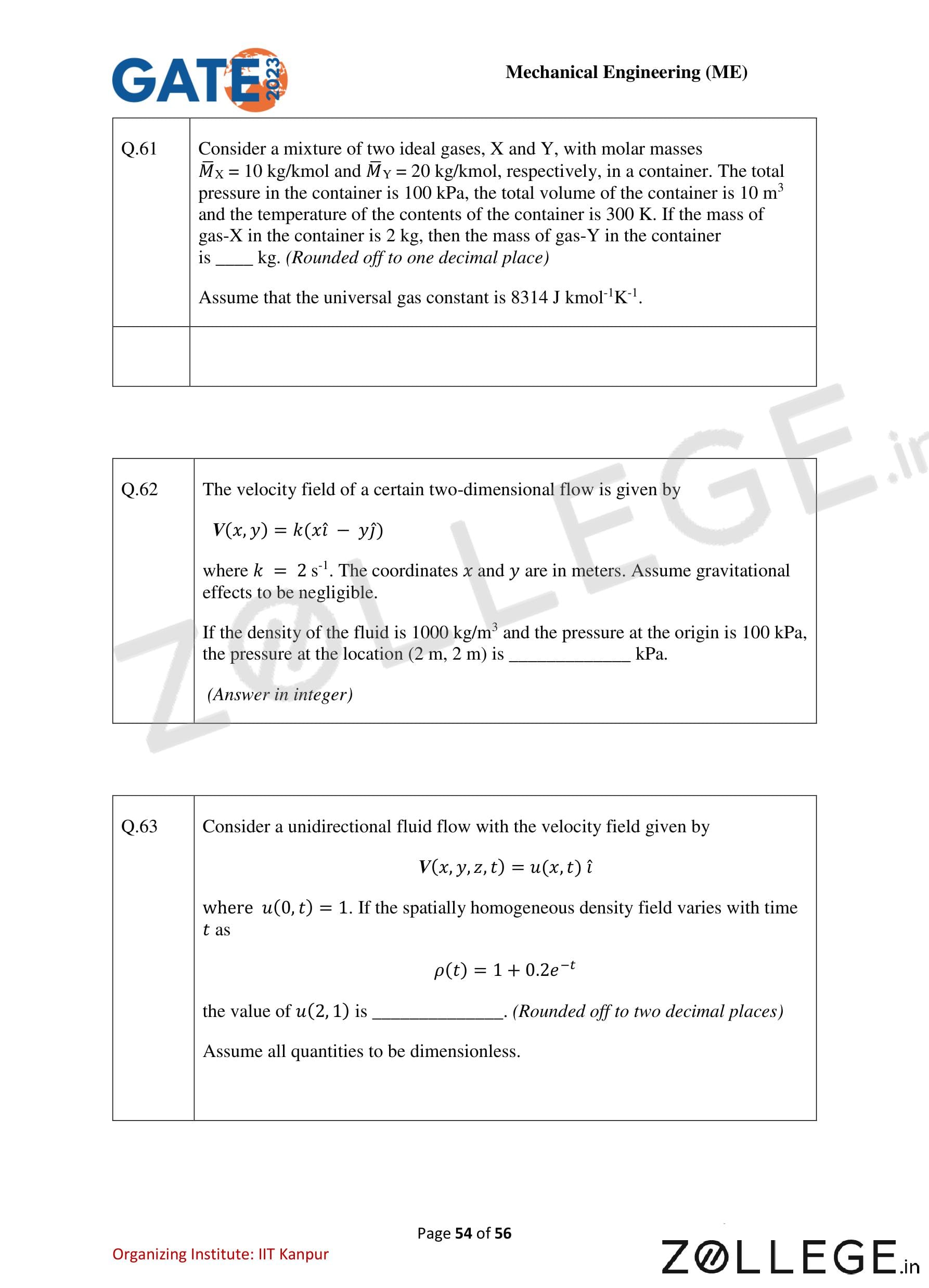
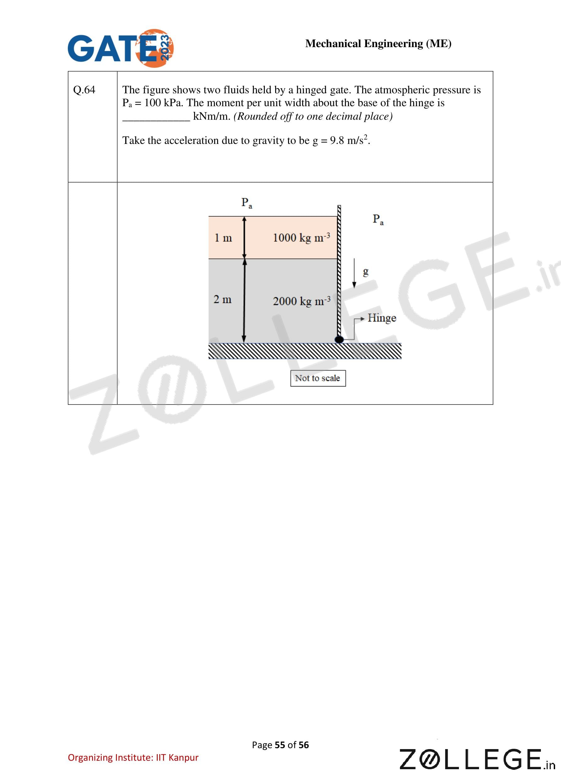
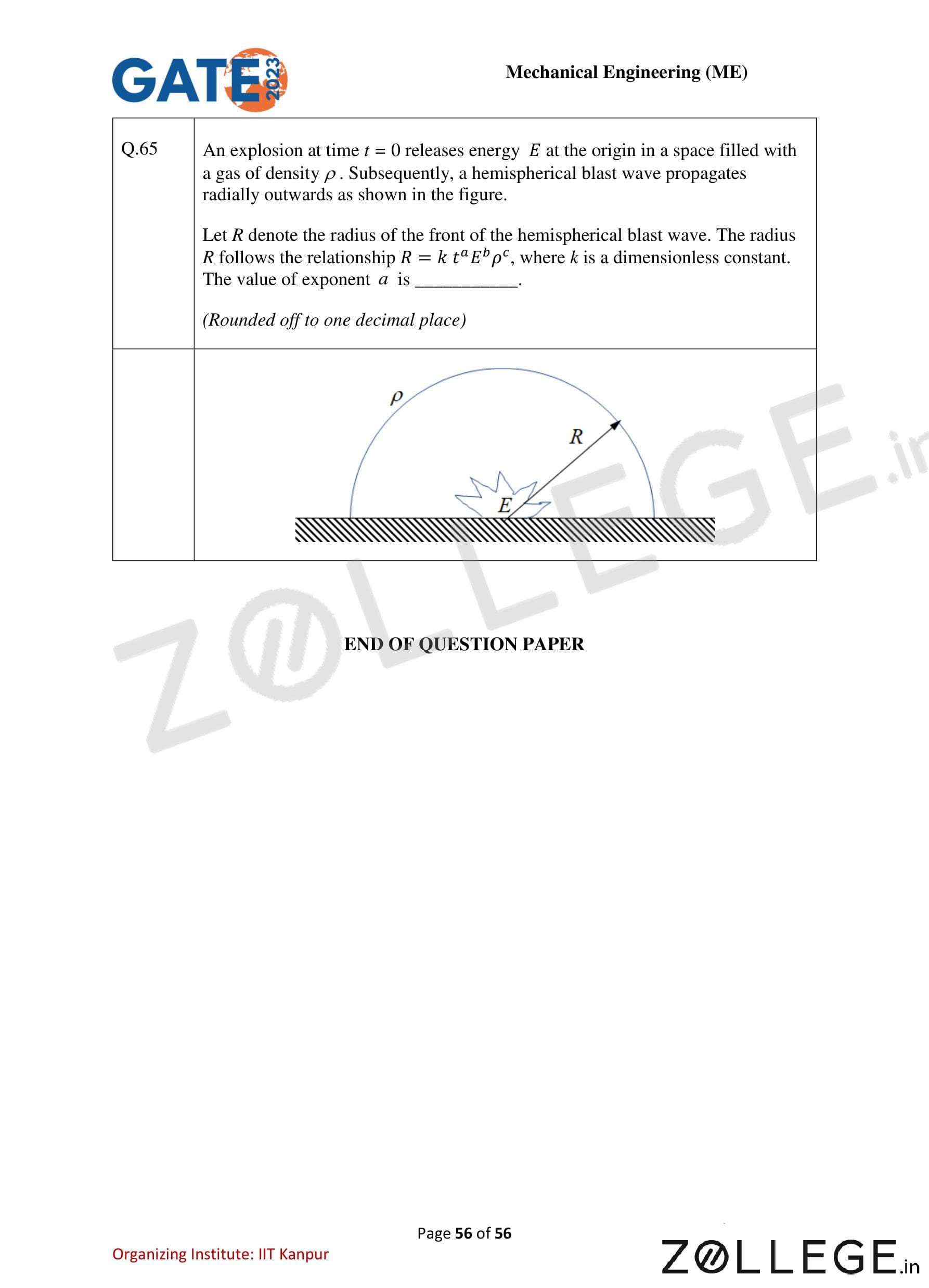
*The article might have information for the previous academic years, please refer the official website of the exam.