
GATE 2024 Electronics and Communication Engineering (ECE) Question Paper Pdf - Check Solutions with Answer Key Pdf
- Chemistry Syllabus
- Maths Syllabus
- Physics Syllabus
- Exam Pattern
- Paper Analysis
- Chemical Engg Syllabus
- Civil Engg Syllabus
- ECE Syllabus
- Mechanical Engg Syllabus
- Engg Science Syllabus
- Mining Engg Syllabus
- IN Syllabus
- CSE Syllabus
- EE Syllabus
- AE Syllabus
- BM Syllabus
- GG Syllabus
- EY Syllabus
- ST Syllabus
- TF Syllaus
- AR Syllabus
- XL Syllabus
- MT Syllabus
- PI Syllabus
- PE Syllabus
- ME Pattern
- TF Pattern
- CE Pattern
- EE Pattern
- EC Pattern
- CS Pattern
- BT Pattern
- BM Pattern
- IN Pattern
- DA Syllabus
- NA & ME Syallabus
- ES & Engg Syllabus
- Geomatics Engg Syllabus
- Agri Engg Syllabus
- Humanities and Social Sci
- PI Syllabus

.jpg?tr=h-55,w-55,c-force)
Content Strategist|Tech-innovator|National Hackathon Winner | Updated On - Feb 3, 2025
The GATE 2024 Electronics and Communication Engineering (ECE) Question Paper with Answer Key PDF is available for download. The exam was successfully conducted by IISc Bangalore on February 11, 2024, in the forenoon session from 9:30 AM to 12:30 PM. As per the students’ initial reactions, the GATE 2024 ECE Question Paper was reported as Moderately Challenging. The General Aptitude section was considered Easy to Moderate, the Engineering Mathematics section was of Moderate difficulty, while the Core ECE were reported as Difficult by most students.
GATE 2024 Electronics and Communication Engineering (ECE) Question Paper with Answer Key PDF
Candidates can download the GATE 2024 Electronics and Communication Engineering (ECE) Question Paper with Answer Key PDFs using the link below.
| GATE 2024 Electronics and Communication Engineering (ECE) Question Paper with Answer Key |  Download Download |
Check Solution |
GATE Electronics and Communication Engineering (ECE) 2024 Questions with Solutions
GENERAL APTITUDE
Question 1:
If ‘→' denotes increasing order of intensity, then the meaning of the words [charm → enamor → bewitch] is analogous to [bored → ____ → weary]. Which one of the given options is appropriate to fill the blank?
View Solution
Solution: The question describes a progression of intensity in the given contexts.
- In the first analogy [charm → enamor → bewitch], the intensity of attraction or fascination increases.
- Similarly, in [bored → ____ → weary], the progression reflects increasing exhaustion or disinterest.
The word jaded fits perfectly between bored and weary as it indicates a state of tiredness or overexposure leading to weariness.
Final Answer: (1) jaded
Question 2:
P, Q, R, S, and T have launched a new startup. Two of them are siblings. The office of the startup has just three rooms. All of them agree that the siblings should not share the same room. If S and Q are single children, and the room allocations shown below are acceptable to all:
P, R T, S Q
P, Q R, T S
Then, which one of the given options is the siblings?
View Solution
Solution: Step 1: Analyze the problem and conditions. - The siblings cannot share the same room.
- S and Q are single children, so they cannot have siblings.
Step 2: Examine the given room allocations. - In the first allocation: [P, R], [T, S], [Q]. P and R share a room, T and S share a room, and Q is alone.
- In the second allocation: [P, Q], [R,T], [S]. P and Q share a room, R and T share a room, and S is alone.
Step 3: Determine the sibling pair. - From the allocations, P and T do not share a room in either allocation.
- P and R, T and R, and other pairs do share rooms in one of the allocations, violating the condition for siblings.
Thus, the sibling pair is P and T. Final Answer: (1) P and T
Question 3:
Five years ago, the ratio of Aman's age to his father's age was 1:4, and five years from now, the ratio will be 2:5. What was his father's age when Aman was born?
View Solution
Solution: Step 1: Let Aman's age 5 years ago be x, and his father's age 5 years ago be 4x.
- Current age of Aman = x +5
- Current age of his father = 4x + 5
- Aman's age 5 years from now = x + 10
- Father's age 5 years from now = 4x + 10
Step 2: Use the second condition:
Aman's age (5 years from now)⁄Father's age (5 years from now) = 2⁄5
x + 10⁄4x + 10 = 2⁄5
Cross-multiply:
5(x + 10) = 2(4x + 10)
5x + 50 = 8x + 20
50 – 20 = 8x – 5x
3x = 30
x = 10
Step 3: Calculate the father's age when Aman was born: - Aman's current age = x + 5 = 10 + 5 = 15
- Father's current age = 4x + 5 = 40 + 5 = 45
- Father's age when Aman was born = 45 – 15 = 30.
Final Answer: (2) 30 years
Question 4:
For a real number x > 1, solve the equation: 1⁄log2x + 1⁄log3x + 1⁄log4x= 1 The value of x is:
View Solution
Solution: Step 1: Rewrite the logarithmic terms using the change of base formula.
Using the change of base formula logax = logbx⁄logba, the equation becomes: log 2⁄log x + log 3⁄log x + log 4⁄log x= 1
Step 2: Simplify the equation.
Factor out 1⁄log x: 1⁄log x (log 2 + log 3 + log 4) = 1
Simplify the terms inside the parenthesis using log a + log b = log(ab):
log 2 + log 3 + log 4 = log(2.3.4) = log 24
Thus, the equation becomes:
log 24⁄log x= 1
Step 3: Solve for x.
Multiply both sides by log x: log 24 = log x
By the property of logarithms, if log a = log b, then a = b. Hence:
x = 24
Final Answer: (3) 24
Question 5:
The greatest prime factor of (3199 – 3196) is:
View Solution
Solution: Step 1: Simplify the given expression.
The expression can be factored as:
3199 – 3196 = 3196 . (33 – 1)
Step 2: Simplify 33 – 1.
33 = 27 so 33 – 1 = 27 - 1 = 26
Thus, the expression becomes:
3199 - 3196 = 3196 . 26
Step 3: Factorize 26.
The prime factorization of 26 is:
26 = 2 x 13
Step 4: Identify the greatest prime factor. The prime factors of the entire expression are 3, 2, and 13. Among these, the greatest prime factor is:
13
Final Answer: (1) 13
Question 6:
Sequence the following sentences (P, Q, R, S) in a coherent passage:
P: Shifu's student exclaimed, “Why do you run since the bull is an illusion?"
Q: Shifu said, “Surely my running away from the bull is also an illusion."
R: Shifu once proclaimed that all life is illusion.
S: One day, when a bull gave him chase, Shifu began running for his life.
View Solution
Solution: Step 1: Analyze the sentences for logical flow.
- Sentence R introduces Shifu's belief that all life is an illusion, setting the philosophical context.
- Sentence S describes an event where Shifu's actions contradict his proclaimed belief, making it the next logical step. - Sentence P records the student's reaction, questioning Shifu's behavior. - Sentence Q concludes with Shifu's witty justification, tying the narrative together.
Step 2: Arrange the sentences in the correct sequence.
The coherent sequence is: R → S → P → Q
Final Answer: (C) RSPQ
Question 7:
Four identical cylindrical chalk-sticks, each of radius r = 0.5 cm and length l = 10 cm, are bound tightly together using a duct tape as shown in the following figure.
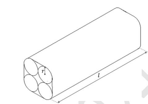
The width of the duct tape is equal to the length of the chalk-stick. The area (in cm²) of the duct tape required to wrap the bundle of chalk-sticks once, is:
View Solution
Solution: Step 1: Analyze the surface to be covered.
The arrangement of four cylinders forms a rectangular cross-section with semicircular ends.
The perimeter to be covered is:
Perimeter = 2(length of rectangle) + 2(semicircular arcs)
The length of the rectangle is 2r + 2r = 4r = 4(0.5) = 2 cm.
The semicircular arcs add up to the circumference of one full circle: 2πr = 2π(0.5) = π cm.
Total Perimeter = 2(2) + π = 4 + π cm
Step 2: Calculate the required area.
The length of the chalk-stick is l = 10 cm. The total area of the duct tape required is:
Area = Perimeter × Length = (4 + π) × 10 = 10(4 + π) cm²
Final Answer: (4) 10(4 + π)
Question 8:
The bar chart shows the data for the percentage of population falling into different categories based on Body Mass Index (BMI) in 2003 and 2023. Based on the data provided, which one of the following options is INCORRECT?

View Solution
Solution: Step 1: Analyze the data from the bar chart.
From the chart: - The percentage of population in the normal category has decreased from 50
- The percentage in the overweight category has increased from 30
- The percentage in the obese category has increased from 10
- The percentage in the underweight category has decreased slightly from 10
Step 2: Validate each statement.
1. Correct: The ratio of overweight to normal increased as overweight grew, and normal decreased.
2. Correct: The ratio of underweight to normal decreased as underweight fell and normal decreased moderately.
3. Incorrect: The ratio of obese to normal increased because obese grew from 10 percentage to 15 percentage , and normal decreased from 50 percentage to 40 percentage.
4. Correct: The percentage of population in the normal category indeed decreased.
Final Answer: (3)
Question 9:
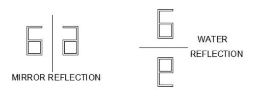
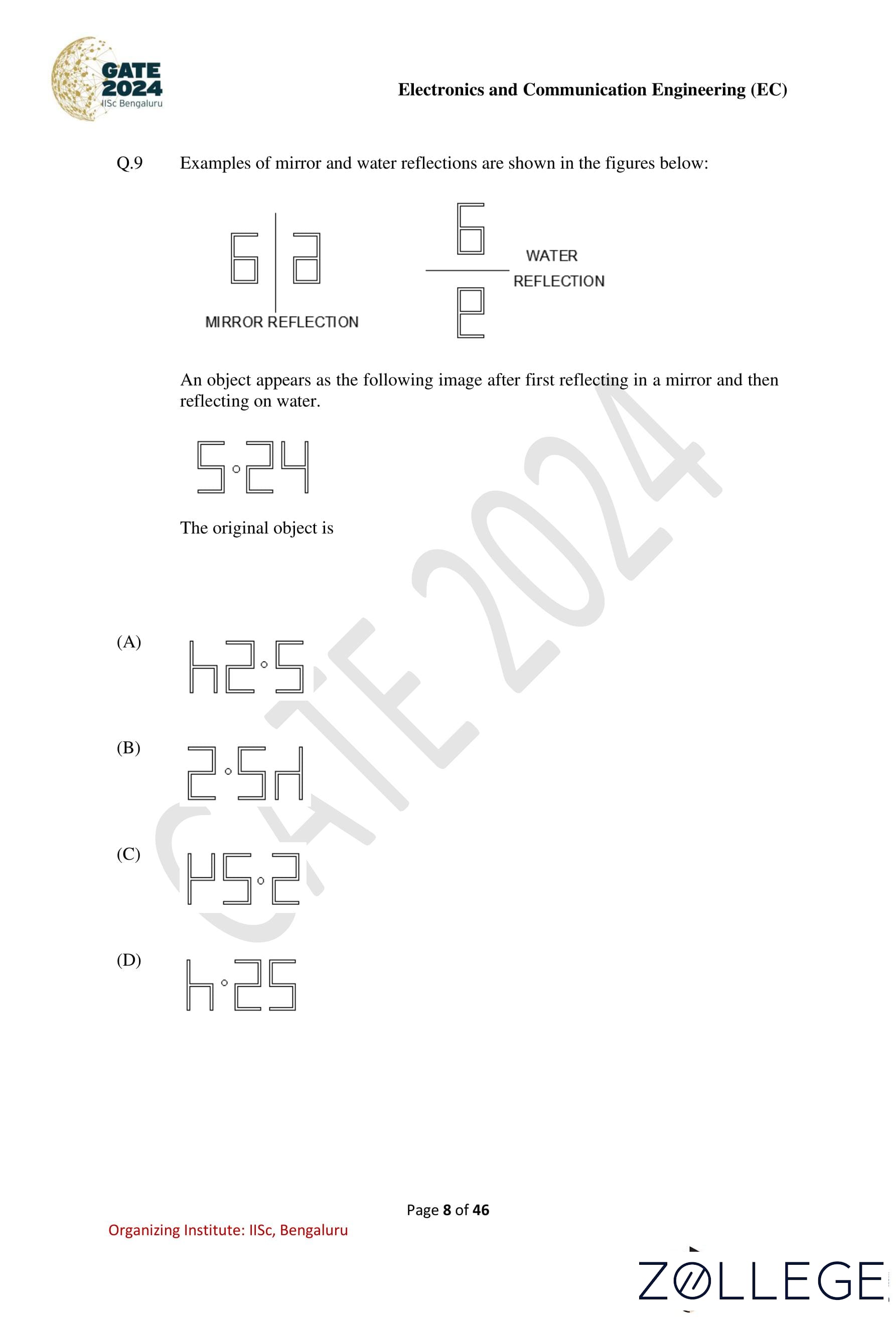
Examples of mirror and water reflections are shown in the figures below:
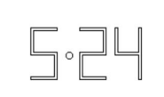
An object appears as the following image after first reflecting in a mirror and then reflecting on water:
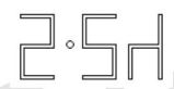
The original object is:

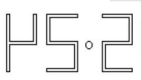


View Solution
Solution: Step 1: Analyze the transformation process.
The object undergoes two transformations:
- Mirror reflection: A horizontal flip of the original object.
- Water reflection: A vertical flip of the mirrored object.
Step 2: Reverse the transformations.
Starting with the final image  , reverse the water reflection (vertical flip) to obtain:

Then reverse the mirror reflection (horizontal flip) to obtain:

Step 3: Verify the final result.
The original object before the transformations is:
Final Answer: (1)
Question 10:
Two identical sheets A and B, of dimensions 24 cm × 16 cm, can be folded into half using two distinct operations, FO1 or FO2. In FO1, the axis of folding remains parallel to the initial long edge, and in FO2, the axis of folding remains parallel to the initial short edge. If sheet A is folded twice using FO1, and sheet B is folded twice using FO2, the ratio of the perimeters of the final shapes of A and B is:
View Solution
Solution: Step 1: Fold sheet A twice using FO1.
- In FO1, the sheet is folded along the long edge. After the first fold, the dimensions of sheet A become: 24⁄2 cm x 16 cm = 12 cm x 16 cm.
- After the second fold along the long edge, the dimensions become: 12⁄2 cm x 16cm = 6cm × 16 cm.
- The perimeter of the final shape of A is:
2 × (6 + 16) = 2 × 22 = 44 cm.
Step 2: Fold sheet B twice using FO2.
- In FO2, the sheet is folded along the short edge. After the first fold, the dimensions of sheet B become: 24 cm x 16⁄2 cm = 24 cm x 8 cm.
- After the second fold along the short edge, the dimensions become: 24 cm x 8⁄2 cm = 24 cm x 4cm.
- The perimeter of the final shape of B is:
2 × (24 + 4) = 2 × 28 = 56 cm.
Step 3: Calculate the ratio of perimeters. The ratio of the perimeters of A to B is: 44⁄56= 11⁄14
However, the question asks for the inverse ratio (final to initial), so:
Ratio = 14 : 11.
Final Answer: (1) 14:11
Engineering Mathematics & ECE
Question 11:
The general form of the complementary function of a differential equation is given by:
yc(t) = (At + B)e-2t, where A and B are real constants determined by the initial condition. The corresponding differential equation is:
View Solution
Solution: Step 1: Analyze the complementary function.
The given complementary function is:
yc(t) = (At + B)e-2t.
This indicates a repeated root of -2 in the characteristic equation.
Step 2: Form the characteristic equation.
The complementary solution corresponds to the characteristic equation:
(r + 2)2 = 0
r = -2, -2.
Step 3: Derive the differential equation. The characteristic equation (r + 2)2 = 0 translates to the differential equation:
d2y/dt2 + 4dy/dt + 4y = f(t).
Final Answer: (1) d²y/dt² + 4dy/dt + 4y = f(t)
Question 12:
In the context of Bode magnitude plots, 40 dB/decade is the same as:
View Solution
Solution: Step 1: Define the relationship between decade and octave.
A decade corresponds to a tenfold increase in frequency, while an octave corresponds to a doubling of frequency. The ratio of decade to octave is:
1 decade = log10(10) / log10(2) ≈ 3.32 octaves.
Step 2: Relate 40 dB/decade to dB/octave.
Given that 40 dB/decade is spread across 3.32 octaves, the dB per octave is:
40 dB / 3.32 octaves ≈ 12 dB/octave.
Final Answer: (1) 12 dB/octave
Question 13:
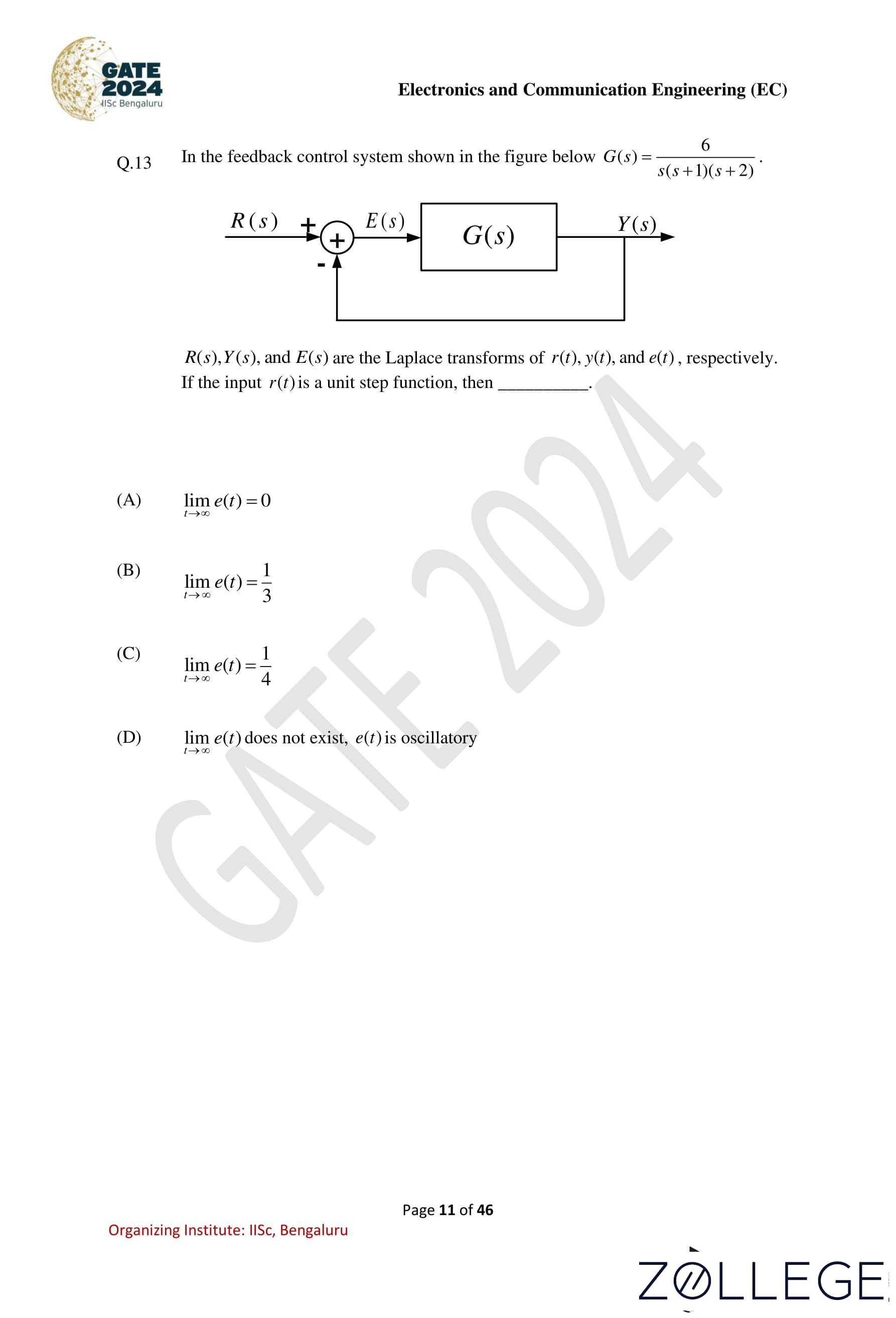
In the feedback control system shown in the figure below,
G(s) = 6⁄s(s+1)(s+2)
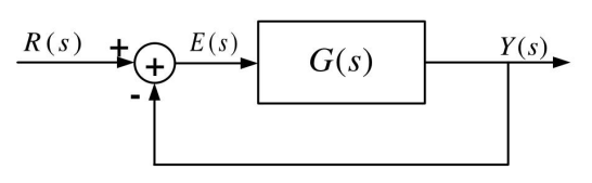
R(s), Y(s), and E(s) are the Laplace transforms of r(t), y(t), and e(t), respectively. If the input r(t) is a unit step function, then:
View Solution
Solution: Step 1: Express the transfer function and input.
The open-loop transfer function is:
G(s) = 6⁄s(s+1)(s+2)
The input r(t) is a unit step function, so: R(s) = 1⁄s
Step 2: Determine the error signal E(s).
In a feedback system:
E(s) = R(s) – Y(s), where Y(s) is the output signal given by: Y(s) = G(s)E(s)
⇒ E(s) = R(s)⁄1+G(s)
Substitute G(s) and R(s):
E(s) = 1⁄s 1⁄1+6/s(s+1)(s+2)= 1⁄s s(s+1)(s+2)⁄s(s+1)(s+2)+6 =(s2 + 3s + 2)⁄s(s2 + 3s + 8)
Step 3: Analyze the poles of E(s). The denominator of E(s) is:
s(s2 + 3s + 8).
The quadratic term s2 + 3s + 8 has complex conjugate roots because the discriminant is negative:
Δ = 32 – 4(1)(8) = 9 – 32 = -23.
Thus, the roots are: s = -3⁄2 ± j√23⁄2
Step 4: Conclude the behavior of e(t).
Since the Laplace transform E(s) has complex conjugate poles, the error signal e(t) contains oscillatory terms. As t → ∞, these oscillations persist, so the limit of e(t) does not exist.
Final Answer: (4) limt→∞ e(t) does not exist, e(t) is oscillatory.
Question 14:
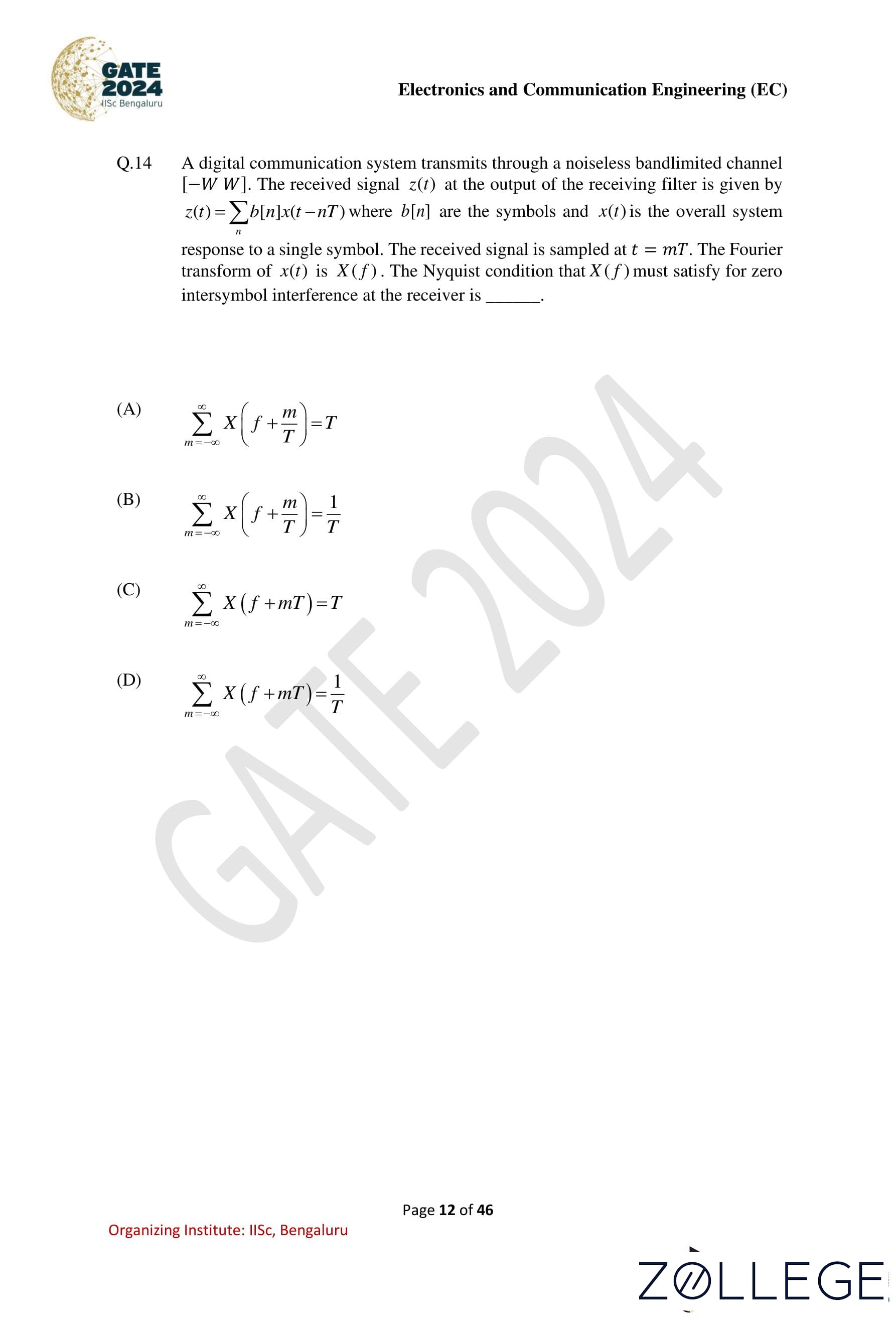
A digital communication system transmits through a noiseless bandlimited channel [-W, W]. The received signal z(t) at the output of the receiving filter is given by:
z(t) = ∑n b[n]x(t − nT), where b[n] are the symbols and x(t) is the overall system response to a single symbol. The received signal is sampled at t = mT. The Fourier transform of x(t) is X(f). The Nyquist condition that X(f) must satisfy for zero intersymbol interference at the receiver is:
View Solution
Solution: Step 1: Understanding the Nyquist Criterion The Nyquist criterion ensures that there is no intersymbol interference (ISI) in a sampled signal. This condition is required to guarantee that the signal z(t) at sampling instances t = mT does not experience overlapping contributions from adjacent symbols.
Step 2: Formulating the Nyquist Condition in the Frequency Domain Given that x(t) is the impulse response of the system, its Fourier transform X(f) should satisfy the Nyquist condition for zero ISI: ∑m=-∞∞ X(f + m⁄T) = T
This condition ensures that the system response is non-overlapping at multiples of the symbol duration T.
Step 3: Explanation of the Summation Property The summation in the frequency domain effectively represents periodic sampling in the time domain. The condition ∑m=-∞∞ X(f + m/T) being equal to T ensures proper pulse shaping and non-overlapping contributions of symbols, enabling accurate recovery of transmitted data.
Step 4: Choosing the Correct Answer Among the given options, the correct condition for zero ISI is: ∑m=-∞∞ X(f + m/T) = T
Final Answer: (1) ∑m=-∞∞ X(f + m/T) = T
Question 15:
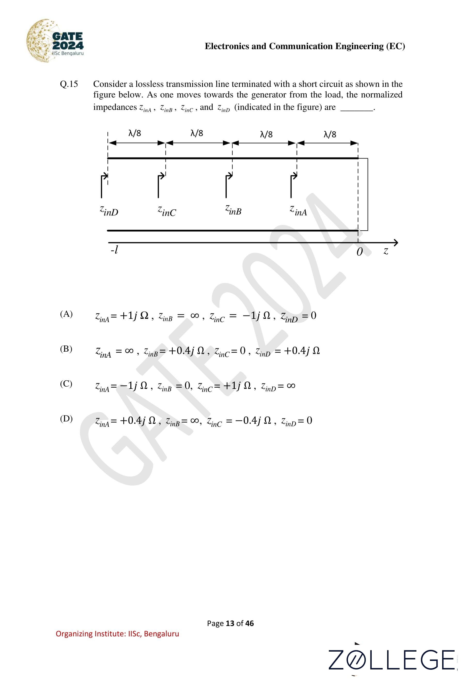
Consider a lossless transmission line terminated with a short circuit as shown in the figure below. As one moves towards the generator from the load, the normalized impedances ZinA, ZinB, ZinC, and zinD (indicated in the figure) are:
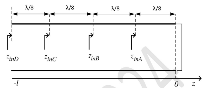
View Solution
Solution: Step 1: Analyze the properties of the lossless transmission line.
For a lossless transmission line terminated with a short circuit, the normalized input impedance at a distance z = –l from the load is given by:
Zin = j tan(2πl⁄λ), where λ is the wavelength.
Step 2: Evaluate the normalized impedances at each point.
- At z = -λ/8 (zinD): ZinD = j tan(-π⁄4) = j(0) = 0.
- At z = -λ/4 (zinC): ZinC = j tan(-π⁄2) = -j∞.
- At z = -3λ/8 (zinB): ZinB = j tan(-<
- At z = -λ/2 (zinA): ZinA = j tan(-π) = +j.
Step 3: Conclude the correct option.
The normalized input impedances are: ZinA = +jΩ, ZinB = ∞, ZinC = -jΩ, ZinD = 0.
Final Answer: (1) zinA = +jΩ, zinB = ∞, zinC = -jΩ, zinD = 0.
Question 16:
Let î and ĵ be the unit vectors along x and y axes, respectively, and let A be a positive constant. Which one of the following statements is true for the vector fields:
F₁ = A(îy + ĵx) and F₂ = A(îy – ĵx)?
View Solution
Solution: Step 1: Define the condition for an electrostatic field.
A vector field F is an electrostatic field if its curl is zero: ∇ × F = 0.
Step 2: Compute the curl of F₁.
F₁ = A(îy + ĵx). The curl of F₁ is:
∇ × F₁ = î j k⁄∂/∂x ∂/∂y ∂/∂z Ay Ax 0⁄∂/∂x ∂/∂y ∂/∂z
Expanding the determinant:
∇ × F₁ = î(∂A⁄∂y - ∂A⁄∂z) - ĵ(∂A⁄∂x - ∂A⁄∂z) + k(∂A⁄∂y - ∂A⁄∂x).
Since Ax and Ay are independent of z, the z-derivatives vanish. The x- and y-derivatives yield: ∇ × F₁ = k(A – A) = 0. Thus, F₁ is an electrostatic field.
Step 3: Compute the curl of F₂.
F₂ = A(îy – ĵx). The curl of F₂ is: ∇ × F₂ = î j k⁄∂/∂x ∂/∂y ∂/∂z Ay -Ax 0⁄∂/∂x ∂/∂y ∂/∂z
Expanding the determinant:
∇ × F₂ = k(A + A) = k(2A). Since the curl is nonzero, F₂ is not an electrostatic field.
Final Answer: (2) Only F₁ is an electrostatic field.
Question 17:
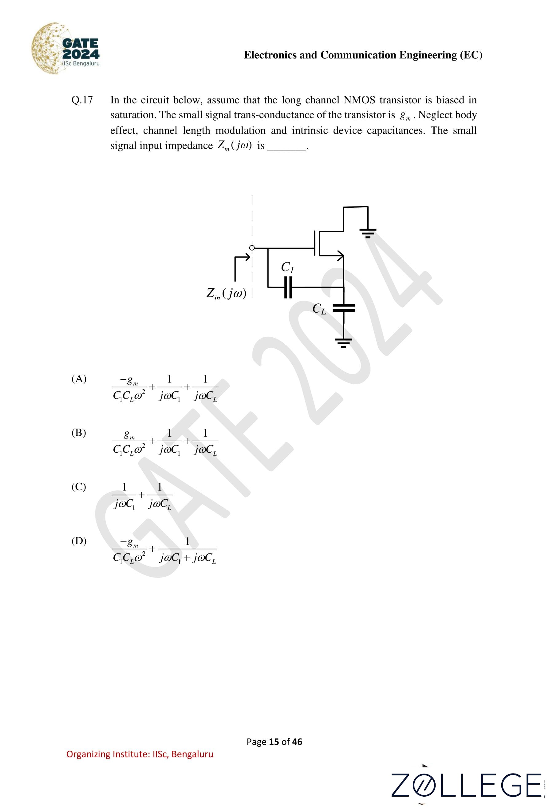
In the circuit below, assume that the long channel NMOS transistor is biased in saturation. The small signal transconductance of the transistor is gm. Neglect body effect, channel length modulation, and intrinsic device capacitances. The small signal input impedance Zin(jw) is:
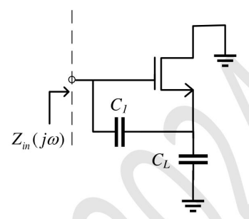
View Solution
Solution: Step 1: Analyze the circuit.
The input impedance Zin(jω) is determined by the equivalent impedance of the capacitor C1, the capacitor CL, and the small signal model of the transistor, which includes the transconductance gm.
Step 2: Derive the input impedance.
The NMOS transistor introduces a dependent current source with transconductance gm, and the capacitors C1 and CL contribute reactive impedances. The impedance due to the capacitors is given by:
ZC1 = 1⁄jωC1 , ZCL = 1⁄jωCL
The transconductance gm contributes a term proportional to –gm, and the capacitors introduce terms proportional to ω2. Combining all contributions, the small signal input impedance is:
Zin(jω) = -gm⁄CLC1ω2 + 1⁄jωC1 + 1⁄jωCL
Step 3: Verify the final expression.
The derived expression matches the option: -gm⁄CLC1ω2 + 1⁄jωC1 + 1⁄jωCL
Final Answer: (1) -gm⁄CLC1ω2 + 1⁄jωC1 + 1⁄jωCL
Question 18:
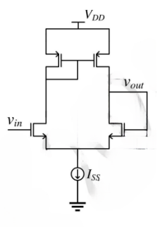
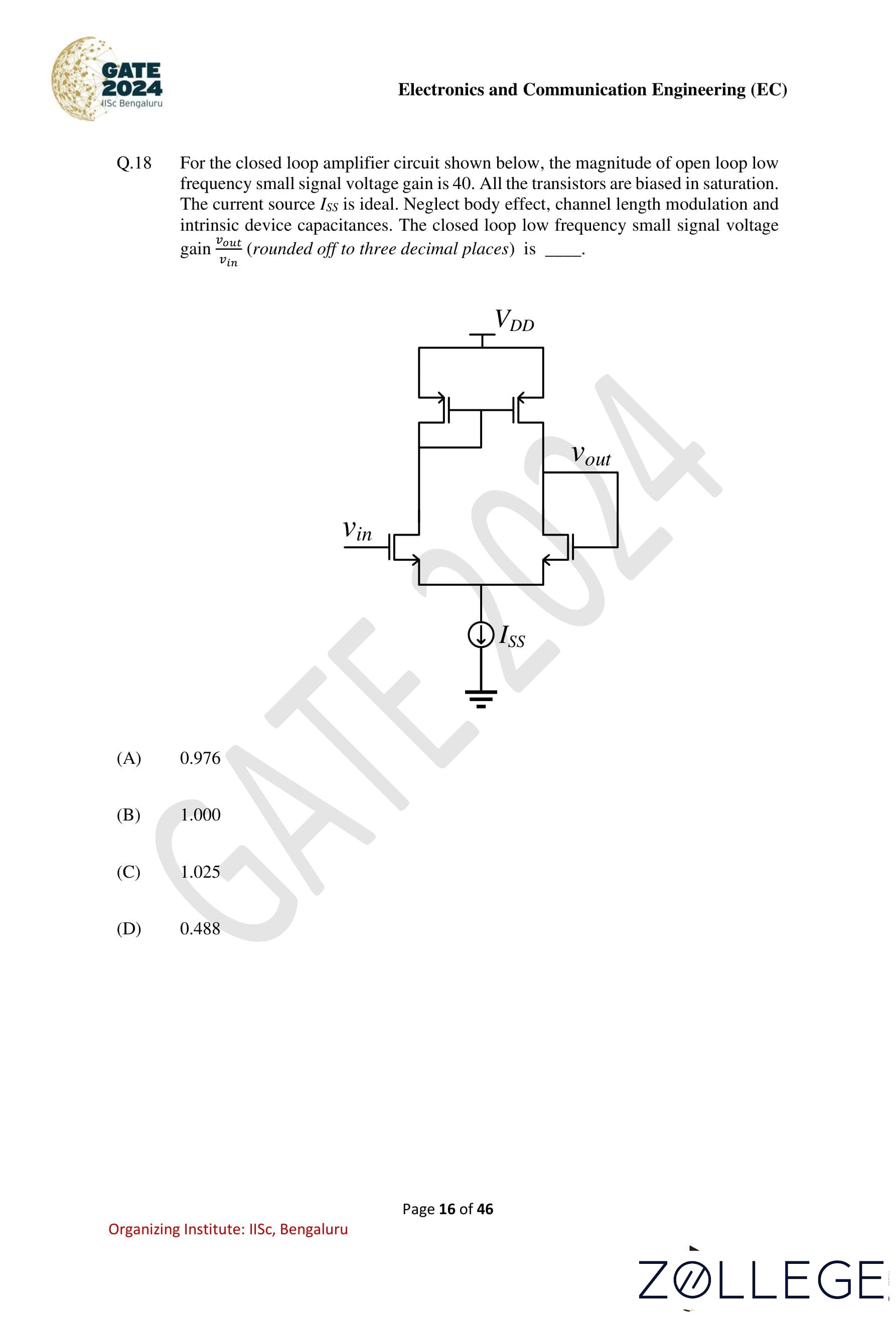
For the closed-loop amplifier circuit shown below, the magnitude of open-loop low-frequency small signal voltage gain is 40. All the transistors are biased in saturation. The current source Iss is ideal. Neglect body effect, channel length modulation, and intrinsic device capacitances. The closed-loop low-frequency small signal voltage gain Vout⁄Vin (rounded off to three decimal places) is:
View Solution
Solution: Step 1: Identifying the circuit type The given circuit is a differential amplifier with a source-coupled pair and an ideal current source Iss. The circuit uses negative feedback.
Step 2: Using the voltage gain formula for negative feedback For a negative feedback amplifier with an open-loop gain of A and feedback factor β, the closed-loop gain is given by:
ACL = A⁄1+Aβ
Step 3: Analyzing the feedback network In the given circuit, the feedback factor β can be found from the resistive feedback network. Since the circuit includes direct feedback from output to input, the feedback factor β is approximately 1.
Step 4: Substituting given values Given that the open-loop gain A is 40 and β = 1:
ACL = 40⁄1+40(1) = 40⁄41 ≈ 0.976
Therefore, the closed-loop voltage gain is 0.976, which matches the given option (1).
Final Answer: 0.976
Question 19:
For the Boolean function: F(A, B, C, D) = ∑m(0, 2, 5, 7, 8, 10, 12, 13, 14, 15), the essential prime implicants are:
View Solution
Solution: Step 1: Identify the minterms.
The given minterms are 0, 2, 5, 7, 8, 10, 12, 13, 14, 15. These minterms correspond to the binary representation of the function.
Step 2: Construct the Karnaugh Map.
Map the minterms onto a 4-variable K-map and group adjacent ones to find prime implicants.
Step 3: Determine essential prime implicants.
From the K-map grouping: Essential prime implicants are: BD and B̅D̅.
Final Answer: (1) BD, B̅D̅
Question 20:
A white Gaussian noise w(t) with zero mean and power spectral density N0⁄2, when applied to a first-order RC low-pass filter produces an output n(t). At a particular time t = tk, the variance of the random variable n(tk) is:
View Solution
Solution: Step 1: Determine the transfer function of the RC low-pass filter.
The transfer function of a first-order RC low-pass filter is:
H(f) = 1⁄1+j2πfRC
Step 2: Relate the power spectral density to the variance.
The output power spectral density Sn(f) is:
Sn(f) = |H(f)|2Sw(f).
For white Gaussian noise, Sw(f) = N0⁄2. The magnitude squared of the transfer function is: |H(f)|2 = 1⁄1+(2πfRC)2.
Step 3: Compute the variance.
The variance of the output n(tk) is the integral of the power spectral density over all frequencies:
Variance = ∫-∞∞ Sn(f) df = ∫-∞∞ N0⁄2 1⁄1+(2πfRC)2 df.
Substituting ω = 2πf, the integral becomes: Variance = N0⁄2 ∫-∞∞ 1⁄1+(ωRC)2dω⁄2π
The standard integral for 1⁄1+x2 yields:
∫-∞∞ 1⁄1+(ωRC)2 dω = π⁄RC
Thus, the variance is:
Variance = N0⁄2 * π⁄2π * 1⁄RC = N0⁄4RC
Final Answer: (1) N0⁄4RC
Question 21:
A causal and stable LTI system with impulse response h(t) produces an output y(t) for an input signal x(t). A signal x(0.5t) is applied to another causal and stable LTI system with impulse response h(0.5t). The resulting output is:
View Solution
Solution: Step 1: Recall the properties of LTI systems under scaling.
For a causal and stable LTI system, the output y(t) is given by the convolution of the input x(t) with the impulse response h(t): y(t) = x(t) * h(t).
When the input x(t) is scaled by x(at) and the impulse response is scaled by h(at), the resulting output becomes:
y(t) → 1⁄a y(t⁄a).
Step 2: Apply the given conditions.
Here, the input is x(0.5t) and the impulse response is h(0.5t). Substituting α = 0.5 into the scaling property:
y(t) → 1⁄0.5 y(t⁄0.5) = 2y(0.5t).
Step 3: Verify the result.
The output of the second LTI system is scaled by a factor of 2 and compressed by a factor of 0.5, resulting in: 2y(0.5t)
Final Answer: (1) 2y(0.5t)
Question 22:
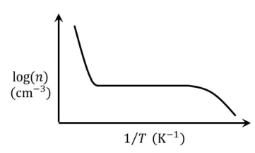
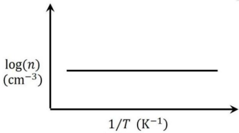
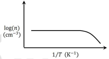
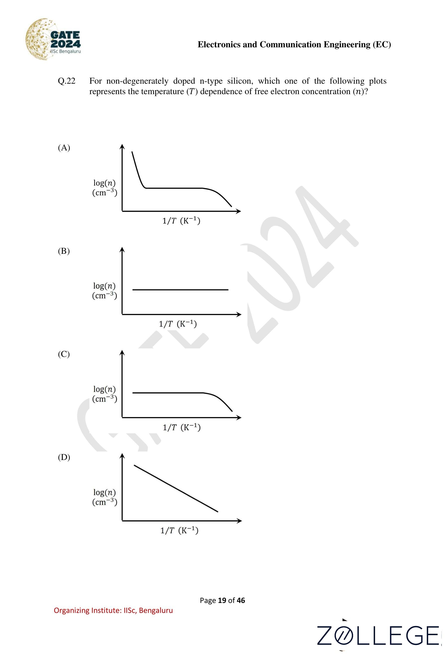
For non-degenerately doped n-type silicon, which one of the following plots represents the temperature (T) dependence of free electron concentration (n)?
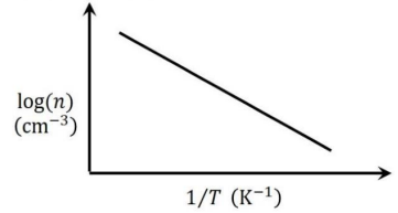
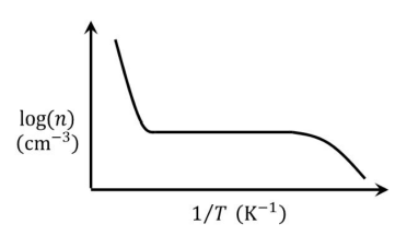
View Solution
Solution: Step 1: Recall the temperature dependence of carrier concentration in n-type silicon. For non-degenerately doped n-type silicon: 1. At low temperatures, the majority carriers (n) are determined by the donor atom ionization, which becomes temperature-independent (saturated). 2. At high temperatures, intrinsic carrier generation dominates, and n increases due to thermal excitation.
Step 2: Interpret the plot.
1. At low 1/T (high temperatures), intrinsic excitation starts contributing, causing a slight increase in carrier concentration.
2. At high 1/T (low temperatures), the donor ionization dominates, leading to a saturation in n.
Step 3: Match with the given plots.
From the given options, only plot (A) accurately represents the described behavior:
- Saturation at low 1/T
- Slight decrease at high 1/T due to temperature effects.
Final Answer: (1) 
Question 23:
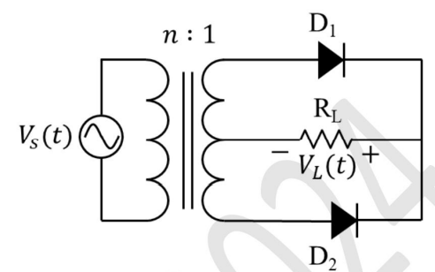
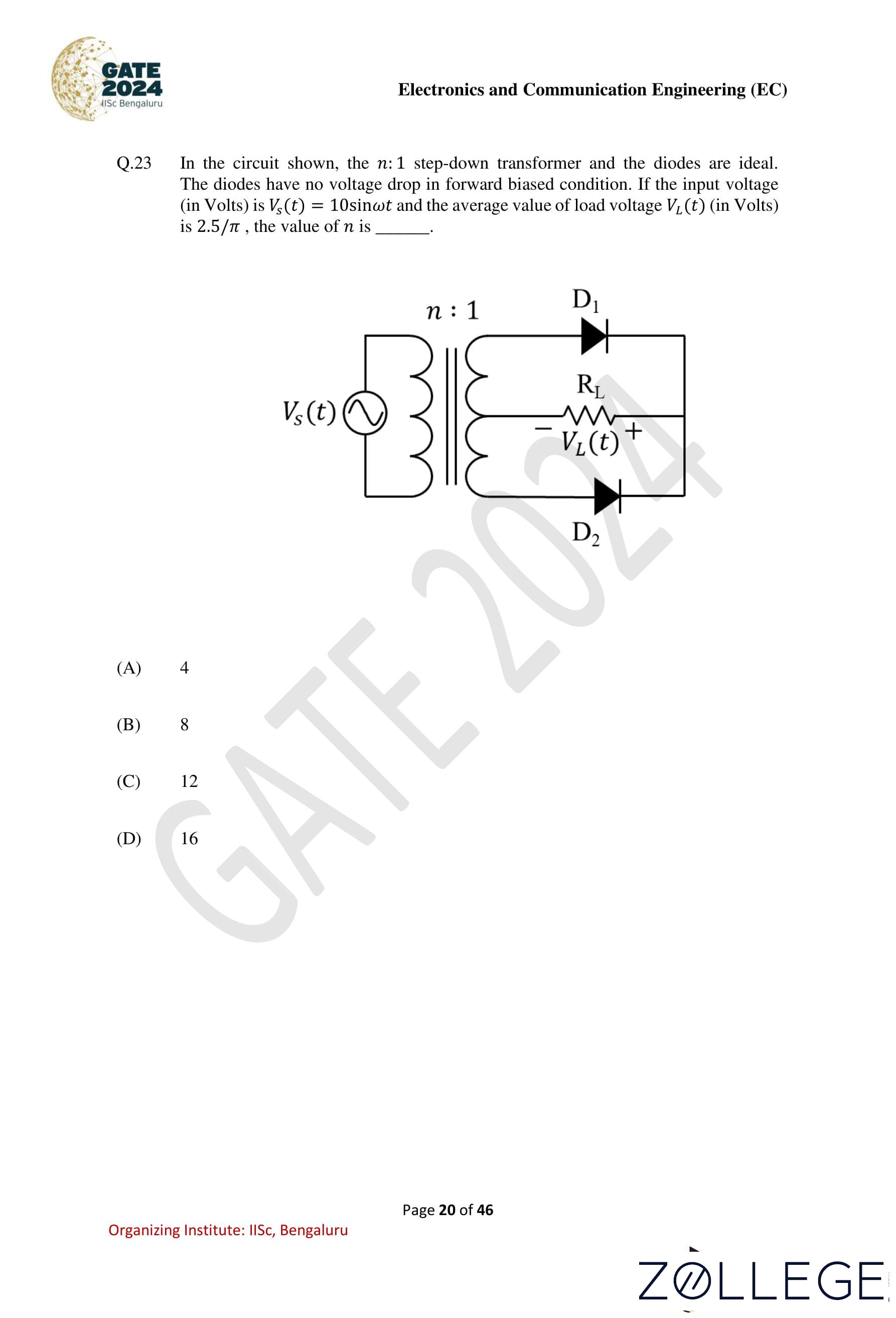
In the circuit shown, the n : 1 step-down transformer and the diodes are ideal. The diodes have no voltage drop in forward-biased condition. If the input voltage (in Volts) is Vs(t) = 10 sin ωt and the average value of load voltage VL(t) (in Volts) is 2.5/π, the value of n is ____.
View Solution
Solution: Step 1: Understanding the circuit operation The given circuit is a full-wave rectifier with a center-tapped transformer. The output voltage across the load resistor RL is the rectified version of the secondary voltage.
Step 2: Transformer voltage relationship The primary voltage is given as: Vs(t) = 10 sin ωt
The secondary voltage Vsec(t) will be scaled by the transformer turns ratio n : 1:
Vsec(t) = 10⁄n sin ωt
Step 3: Rectified output voltage For a full-wave rectifier, the output is the absolute value of the input waveform: VL(t) = | 10⁄n sin ωt|
Step 4: Calculating the average voltage The average value of a full-wave rectified sine wave is given by: Vavg = 2Vpeak⁄π
Substituting the given values: 2⁄π * 10⁄n = 2.5⁄π
Step 5: Solving for n Canceling 2⁄π from both sides:
10⁄n = 2.5 , 10⁄2.5 = n, n = 4
Thus, the correct value of n is 4, which corresponds to option (1).
Final Answer: (1) 4
Question 24:
For a causal discrete-time LTI system with transfer function: H(z) = 2z2 + 3⁄(z + 1⁄3)(z - 1⁄2) which of the following statements is/are true?
View Solution
Solution: Step 1: Check system stability.
A system is stable if all poles lie within the unit circle. Here, the poles are at z = -1⁄3 and z = 1⁄2, both within the unit circle. Therefore, the system is stable.
Step 2: Check for minimum phase.
A system is minimum phase if all zeros lie within the unit circle. The zeros of H(z) are outside the unit circle, so the system is not minimum phase.
Step 3: Initial value of the impulse response.
The initial value of the impulse response corresponds to H(z) evaluated at z = ∞:
H(∞) = 2(∞)2 + 3⁄(∞ + 1⁄3)(∞ - 1⁄2) = 2.
Step 4: Final value of the impulse response.
The final value theorem does not apply since the system is causal and the denominator has a pole at z = 1. Thus, the final value is 0.
Final Answer: (1), (3), (4)
Question 25:
Let ρ(x, y, z, t) and u(x, y, z, t) represent density and velocity, respectively, at a point (x, y, z) and time t. Assume ∂ρ⁄∂t is continuous. Let V be an arbitrary volume in space enclosed by the closed surface S, and ĥ be the outward unit normal of S. Which of the following equations is/are equivalent to:
∂ρ⁄∂t + ∇ ⋅ (ρu) = 0?
View Solution
Solution: Step 1: Apply the divergence theorem. Using the divergence theorem, the volume integral of ∇ ⋅ (ρu) can be expressed as:
∫V ∇ ⋅ (ρu)dv = ∫S ρu ⋅ ĥ ds.
Step 2: Analyze the given options. From the continuity equation:
∫V ∂ρ⁄∂t dv = -∫V ∇⋅ (ρu)dv.
Using the divergence theorem:
∫V ∂ρ⁄∂t dv = - ∫S ρu ⋅ ĥ ds.
Step 3: Match with options. Options (1) and (3) satisfy the continuity equation, while (2) and (4) do not.
Final Answer: (1), (3)
Question 26:
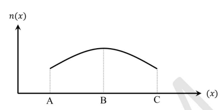
The free electron concentration profile n(x) in a doped semiconductor at equilibrium is shown in the figure, where the points A, B, and C mark three different positions. Which of the following statements is/are true?
View Solution
Solution: Step 1: Analyze the concentration gradient.
The electron diffusion current flows from regions of high concentration to low concentration. Between B and C, the electron concentration decreases, so the diffusion current flows from C to B.
Step 2: Analyze the electric field direction.
The electric field is established due to the gradient in carrier concentration. It opposes the diffusion current. Hence, the electric field points from B to C.
Final Answer: (1), (2), (3)
Question 27:
A machine has a 32-bit architecture with 1-word long instructions. It has 24 registers and supports an instruction set of size 40. Each instruction has five distinct fields, namely opcode, two source register identifiers, one destination register identifier, and an immediate value. Assuming that the immediate operand is an unsigned integer, its maximum value is ____.
View Solution
Solution: Step 1: Determine the bit allocation for instruction fields.
The total instruction size is 32 bits. Fields include:
- Opcode: Supports 40 instructions, requiring [log240] = 6 bits.
- Source Registers: Each requires [log224] = 5 bits. Two source registers require 2×5 = 10 bits.
- Destination Register: Requires [log224] = 5 bits.
- Immediate Value: Remaining bits in the instruction.
Step 2: Calculate the bits allocated for the immediate value.
Bits for immediate value = 32 – (6 + 10 + 5) = 11.
Step 3: Calculate the maximum value of the immediate operand.
An 11-bit unsigned integer has a maximum value of: 211 - 1 = 2047.
Final Answer: 2047
Question 28:
An amplitude modulator has output (in Volts): s(t) = A cos(400πt) + B cos(360πt) + B cos(440πt). The carrier power normalized to 1Ω resistance is 50 Watts. The ratio of the total sideband power to the total power is 1
/9. The value of B (in Volts, rounded off to two decimal places) is ____
View Solution
Solution: Step 1: Power distribution in amplitude modulation.
The carrier power is: Pc = A2⁄2×1Ω = 50 Watts.
Thus: A2 = 100.
Step 2: Total sideband power.
The total sideband power is the sum of the powers of the two sideband components:
PSB = B2⁄2 + B2⁄2 = B2.
Step 3: Power ratio.
The total power is the sum of the carrier power and sideband power: Ptotal = Pc + PSB = 50 + B2.
The given ratio of sideband power to total power is: PSB⁄Ptotal = 1⁄9
Substitute PSB = B2 and Ptotal = 50 + B2:
B2⁄50+B2 = 1⁄9
Step 4: Solve for B2.
Simplify:
9B2 = 50 + B2 ⇒ 8B2 = 50 ⇒ B2 = 50⁄8= 6.25.
Thus: B = √6.25 = 2.50 Volts.
Final Answer: 2.50
Question 29:
In a number system of base r, the equation x2 − 12x + 37 = 0 has x = 8 as one of its solutions. The value of r is ____.
View Solution
Solution: Step 1: Substitute x = 8 into the equation.
In base r, the coefficients 12 and 37 are represented as: 12 = 1r + 2, 37 = 3r + 7.
Substitute x = 8 into the equation: 82 − (1r + 2).8 + (3r + 7) = 0.
Step 2: Simplify the equation.
Expand: 64 − (1r + 2). 8 + (3r + 7) = 0
Simplify: 64 – 8r – 16 + 3r + 7 = 0 ⇒ -5r + 55 = 0.
Step 3: Solve for r.
5r = 55 ⇒ r = 11.
Final Answer: (3) 11
Question 30:
Let ℝ and ℝ3 denote the set of real numbers and the three-dimensional vector space over it, respectively. The value of α for which the set of vectors: {[2 3 α], [3 -1 3], [1 -5 7]} does not form a basis of ℝ3 is ____.
View Solution
Solution: Step 1: Condition for basis formation A set of vectors forms a basis for ℝ3 if and only if they are linearly independent, which requires the determinant of the corresponding matrix to be non-zero.
Step 2: Construct the matrix The given vectors can be arranged as rows (or columns) of the matrix: A = 2 -3 α⁄3 -1 3 1 -5 7⁄3 -1 3
Step 3: Compute the determinant Expanding the determinant of the matrix:
2 -3 α⁄3 -1 3 1 -5 7⁄3 -1 3
Expanding along the first row: = 2((-1)(7) - (3)(-5)) - (-3)((3)(7) - (3)(1)) + α((3)(-5) - (-1)(1))
= 2 (-7+15) + 3 (21 − 3) + α (−15 + 1)
= 2(8) + 3(18) + α(-14)
= 16 + 54 – 14α
= 70 – 14α
Step 4: Find condition for dependence For the vectors to be linearly dependent, the determinant must be zero:
70 – 14α = 0, α = 5
Therefore, the given set of vectors does not form a basis of R³ when α = 5.
Final Answer: 5
Question 31:
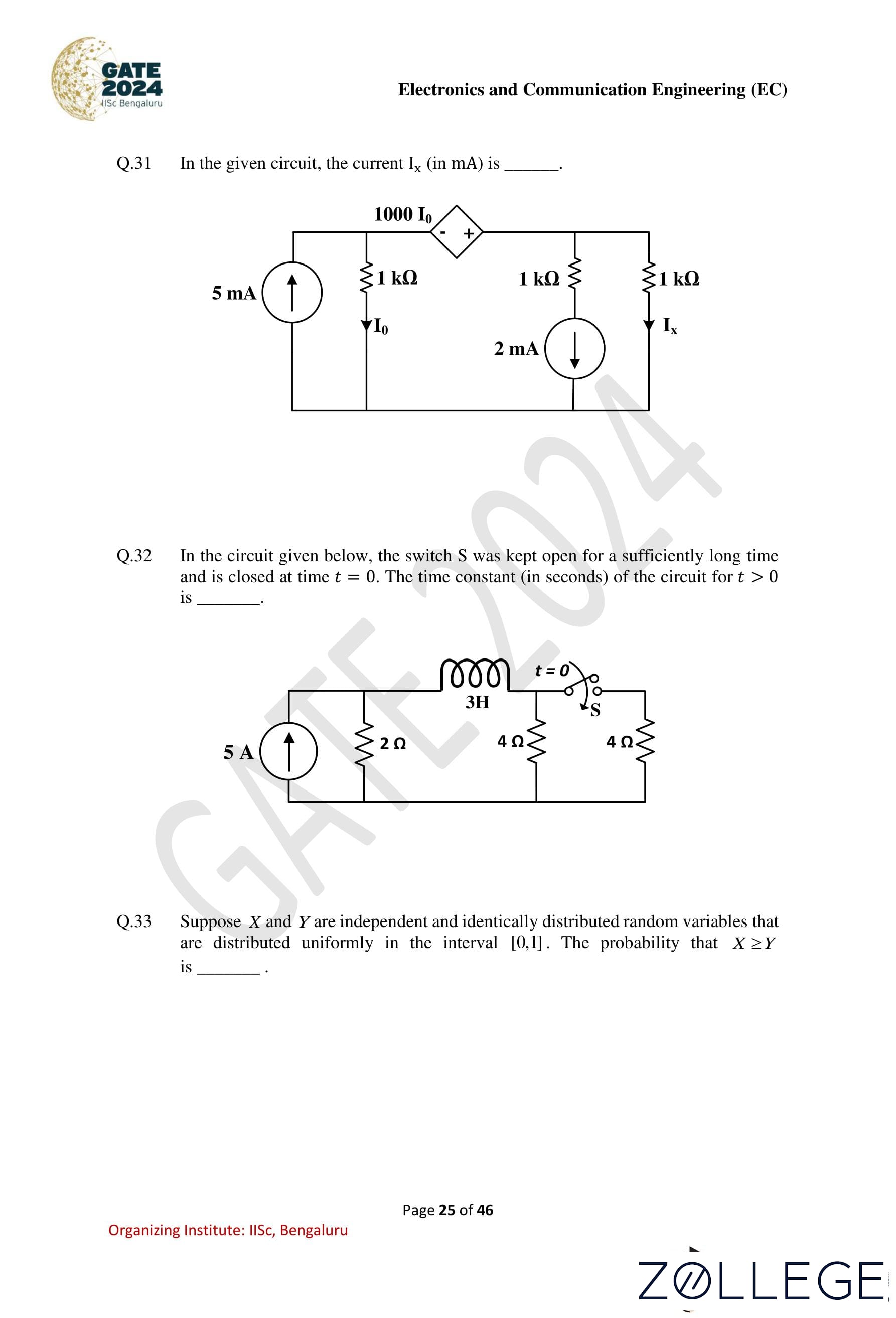
In the given circuit, the current Ix (in mA) is ____.
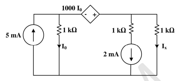
View Solution
Solution: Step 1: Analyze the current division.
The circuit contains a current source of 5 mA, a dependent source 1000Io, and resistors. Apply Kirchhoff's Current Law (KCL) at the node containing Ix.
Step 2: Define the currents.
Let the current through the first resistor be Io = 2 mA. The dependent current source provides 1000Io = 1000 × 2 mA = 2 A.
Step 3: Calculate Ix.
The current Ix flows through the 1 kΩ resistor. Since the currents balance with the dependent source and the resistors, Ix = 2 mA.
Final Answer: 2
Question 32:
In the circuit given below, the switch S was kept open for a sufficiently long time and is closed at time t = 0. The time constant (in seconds) of the circuit for t > 0 is ____. 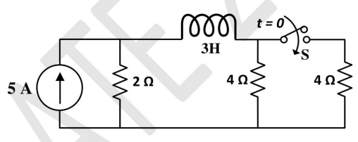
View Solution
Solution: Step 1: Determine the equivalent resistance.
When the switch S is closed, the 4Ω resistors are in parallel:
Req = 4×4⁄4+4 = 2 Ω.
This Req is in series with the 2Ω resistor: Rtotal = 2 + 2 = 4 Ω.
Step 2: Calculate the time constant.
The time constant is: τ = L⁄Rtotal
Substitute L = 3H and Rtotal = 4Ω: τ = 3⁄4 = 0.75 seconds.
Final Answer: 0.75
Question 33:
Suppose X and Y are independent and identically distributed random variables that are distributed uniformly in the interval [0, 1]. The probability that X > Y is ____.
View Solution
Solution: Step 1: Define the probability.
The probability that X > Y is: P(X > Y) = ∫∫(X>Y) fX,Y(x, y) dx dy,
where fX,Y(x, y) = 1 for a uniform distribution over [0, 1].
Step 2: Evaluate the integral.
The region x > y in the unit square [0, 1] × [0, 1] is a triangle with area 1⁄2.
P(X ≥ Y) = ∫01∫0x 1 dy dx = ∫01 x dx = x2⁄2|01 = 1⁄2 = 0.5
Final Answer: 0.50
Question 34:
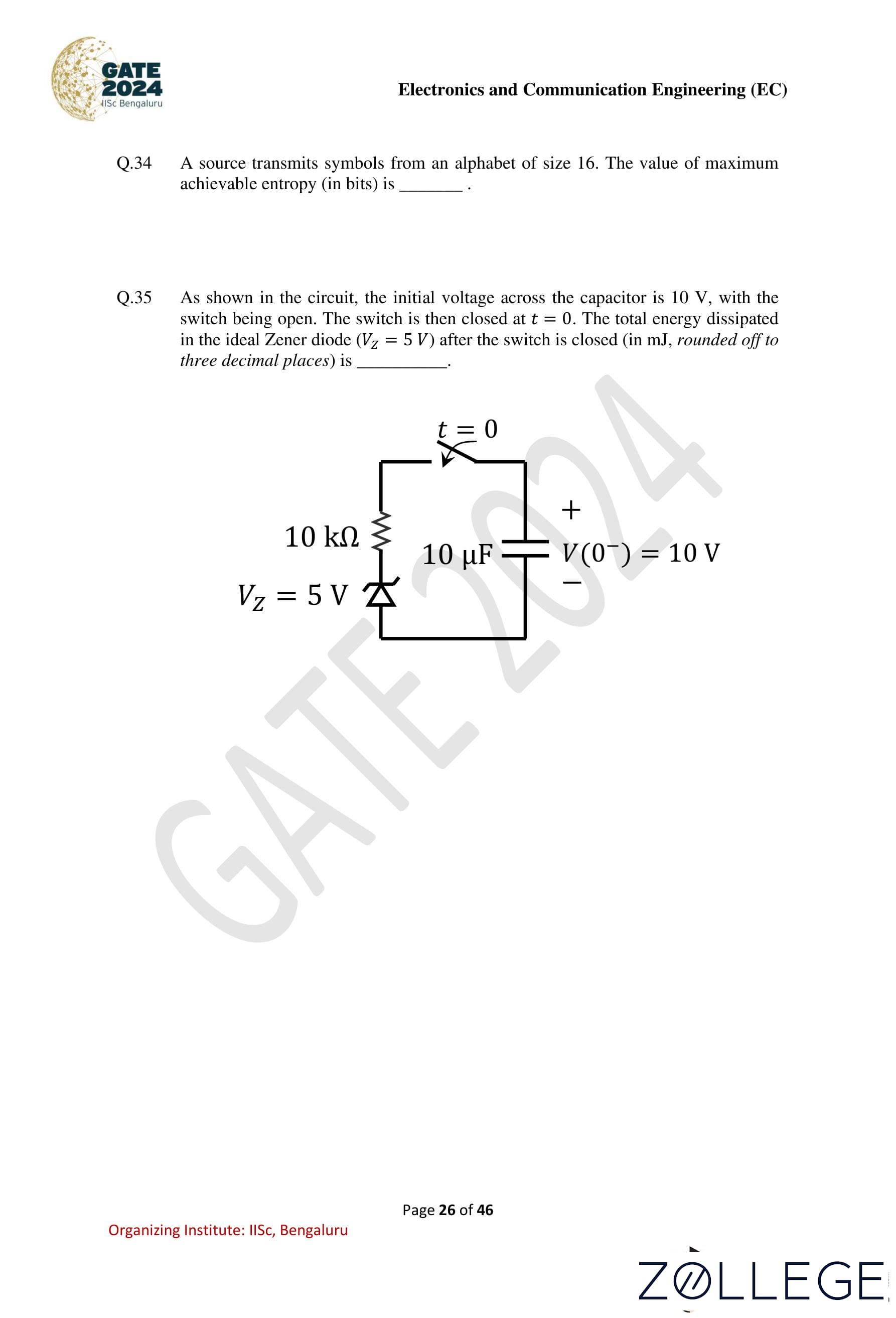
A source transmits symbols from an alphabet of size 16. The value of maximum achievable entropy (in bits) is ____.
View Solution
Solution: Step 1: Recall the formula for maximum entropy.
For a source with an alphabet size N, the maximum entropy Hmax is achieved when all symbols are equally likely. It is given by:
Hmax = log2 N.
Step 2: Substitute N = 16.
Hmax = log2 16 = 4 bits.
Final Answer: 4
Question 35:
As shown in the circuit, the initial voltage across the capacitor is 10 V, with the switch being open. The switch is then closed at t = 0. The total energy dissipated in the ideal Zener diode (Vz = 5 V) after the switch is closed (in mJ, rounded off to three decimal places) is ____.
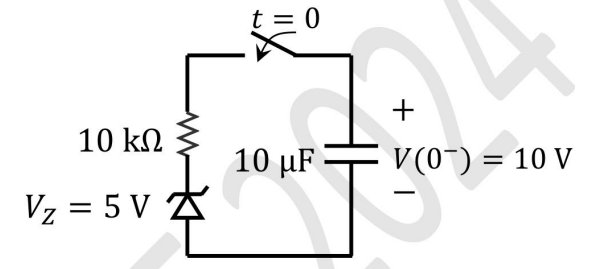
View Solution
Solution: Step 1: Calculate the initial energy stored in the capacitor.
The energy stored in a capacitor is given by: E = 1⁄2 CV2.
Substitute C = 10 μF = 10 × 10-6 F and V = 10 V: Einitial = 1⁄2 × 10 × 10-6 × (10)2 = 0.0005 J.
Step 2: Calculate the final energy in the capacitor. After the switch is closed, the voltage across the capacitor is clamped to Vz = 5 V. The final energy is:
Efinal = 1⁄2 × 10 × 10-6 × (5)2 = 0.000250 J.
Step 3: Calculate the energy dissipated.
The energy dissipated in the Zener diode is the difference between the initial and final energies:
Edissipated = Einitial – Efinal = 0.0005 – 0.000250 = 0.000250 J.
Convert to mJ: Edissipated = 0.250 mJ.
Final Answer: 0.250
Question 36:
Consider the Earth to be a perfect sphere of radius R. Then the surface area of the region, enclosed by the 60°N latitude circle, that contains the north pole in its interior is ____.
View Solution
Solution: Step 1: Surface area formula for a spherical cap.
The surface area of a spherical cap is given by: A = 2πR2(1 – cos θ), where θ is the latitude angle from the equator.
Step 2: Determine cos θ.
For the 60° N latitude, θ = 30° (measured from the pole). Thus: cos 30° = √3⁄2
Step 3: Substitute into the formula.
Substitute R, cos 30° = √3⁄2:
A = 2πR2(1 - √3⁄2) = (2 - √3)πR2.
Final Answer: (1) (2 – √3)πR2
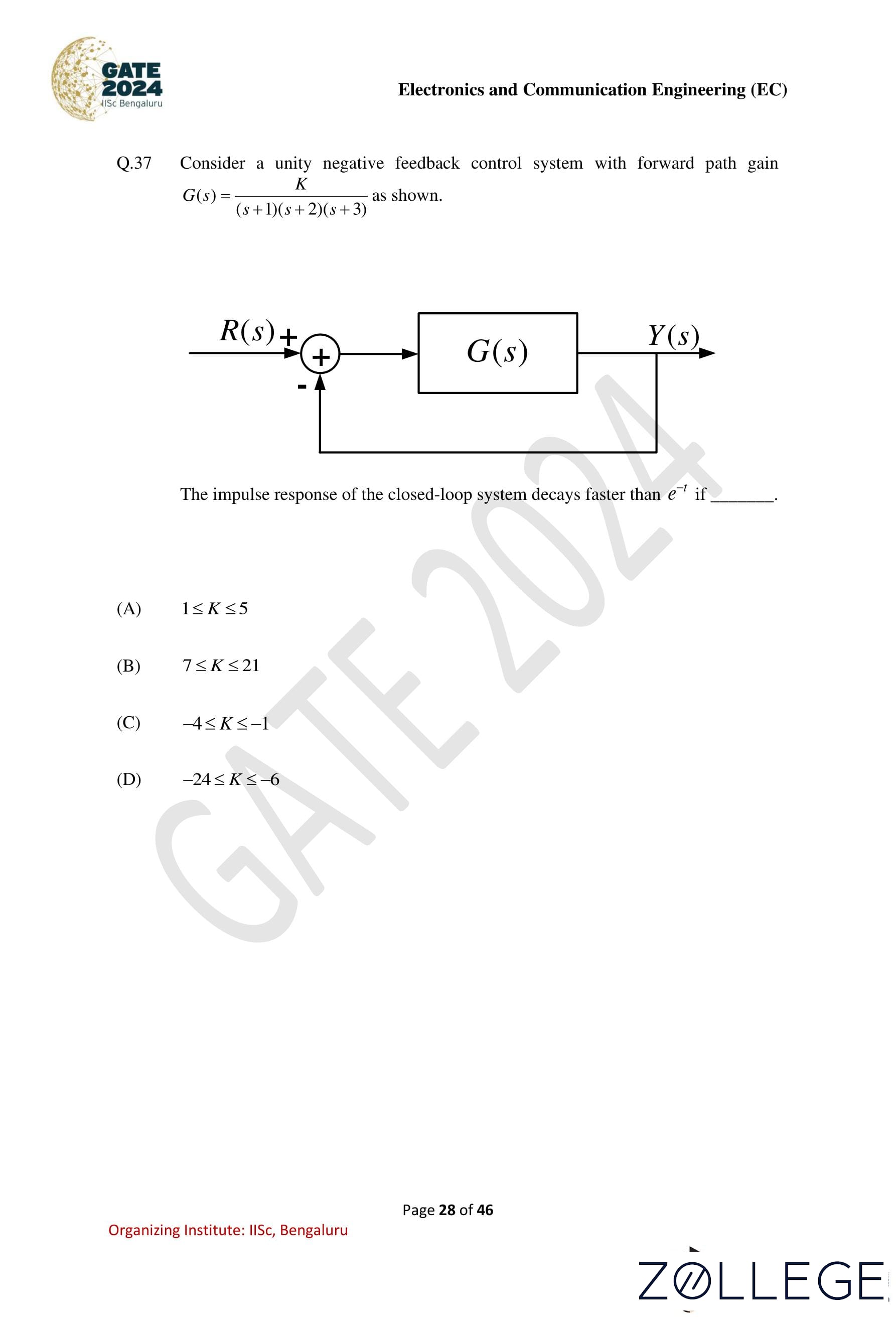
Question 37:
Consider a unity negative feedback control system with forward path gain: G(s) = K⁄(s+1)(s+2)(s+3)
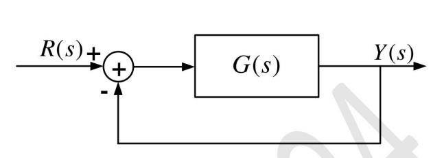
The impulse response of the closed-loop system decays faster than e-t if ____.
View Solution
Solution: Step 1: Closed-loop system characteristic equation.
The closed-loop transfer function is:
T(s) = G(s)⁄1+G(s) = K⁄(s+1)(s+2)(s+3)1⁄1+K/(s+1)(s+2)(s+3)
The characteristic equation is: (s + 1)(s + 2)(s + 3) + K = 0.
Step 2: Decay faster than e-t.
The impulse response decays faster than e-t if all poles of the closed-loop system have a real part less than -1.
Step 3: Determine the range of K.
Solving the characteristic equation for the root locations shows that 1 ≤ K ≤ 5 ensures all poles have real parts less than -1.
Final Answer: (1) 1 ≤ k ≤ 5
Question 38:
A satellite attitude control system, as shown below, has a plant with transfer function: G(s) = 1⁄s2, cascaded with a compensator: C(s) = K(s+α)⁄s+4
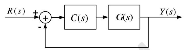
where K and α are positive real constants. In order for the closed-loop system to have poles at −1 ± j√3, the value of α must be ____.
View Solution
Solution: Step 1: Closed-loop transfer function characteristic equation.
The open-loop transfer function is: T(s) = C(s)G(s)⁄1+C(s)G(s)= K(s+α)/(s+4) s2⁄1+K(s+α)/(s+4) s2
The characteristic equation is: s2(s + 4) + K(s + α) = 0.
Step 2: Pole placement condition.
The desired closed-loop poles are at −1±j√3. Substitute these into the characteristic equation to determine α.
Step 3: Solve for α.
Matching coefficients with the expanded form of the characteristic equation yields: α = 1.
Final Answer: (2) 1
Question 39:
A uniform plane wave with electric field: E(x) = Aŷe-j2πx/λ V/m, is traveling in the air (relative permittivity, εr = 1, and relative permeability, μr = 1) in the +x direction. It is incident normally on an ideal electric conductor (conductivity, σ = ∞) at x = 0. The position of the first null of the total magnetic field in the air (measured from x = 0, in meters) is ____.
View Solution
Solution: Step 1: Standing wave condition.
The total magnetic field forms a standing wave due to the reflection from the conductor at x = 0. The nulls of the magnetic field occur at: x = λ⁄4, 3λ⁄4 ,.....
Step 2: Wavelength calculation.
The propagation constant is: β = 2π⁄λ ⇒ λ = 2π⁄β
Substitute β = 2π⁄λ : x = 3 m.
Step 3: First null position.
The first null is at: x = λ⁄4 = 3λ⁄4 m.
Final Answer: (1) λ⁄4
Question 40:
A 4-bit priority encoder has inputs D3, D2, D1, and D0 in descending order of priority. The two-bit output A̅B̅ is generated as 00, 01, 10, and 11 corresponding to inputs D3, D2, D1, and D0, respectively. The Boolean expression of the output bit B is ____.
View Solution
Solution: Step 1: Understanding the priority encoder operation A priority encoder outputs a binary code corresponding to the highest-priority active input. In this 4-bit priority encoder, the input priority order is D3 > D2 > D1 > D0.
Step 2: Analyzing the conditions for output B For bit B, we need to check when it should be high. The truth table for the priority encoder assigns:
B = 1 when D2 = 1 (if D3 is 0) or D1 = 1 (if D3 is 0)
Step 3: Deriving the Boolean expression The conditions can be written as follows:
- If D3 is 0 and D2 is 1, B should be 1 ⇒ D̅3D2.
- If D3 is 0 and D1 is 1, B should be 1 ⇒ D̅3D1.
Combining both cases, the final expression for B is:
B = D̅3D2 + D̅3D1
Thus, the correct Boolean expression is option (2).
Final Answer: (2) D̅3D2 + D̅3D1
Question 41:
The propagation delay of the 2 × 1 MUX shown in the circuit is 10 ns. Consider the propagation delay of the inverter as 0 ns. If S is set to 1, then the output Y is ____. 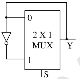
View Solution
Solution: Step 1: Analyze the MUX configuration.
The 2 × 1 MUX selects input 0 or 1 based on the select line S. When S = 1, the output Y reflects input 1, which is a square wave of frequency 50 MHz.
Step 2: Verify propagation delay. The propagation delay of the MUX is 10 ns, but this does not affect the frequency of the square wave.
Final Answer: (2) A square wave of frequency 50 MHz
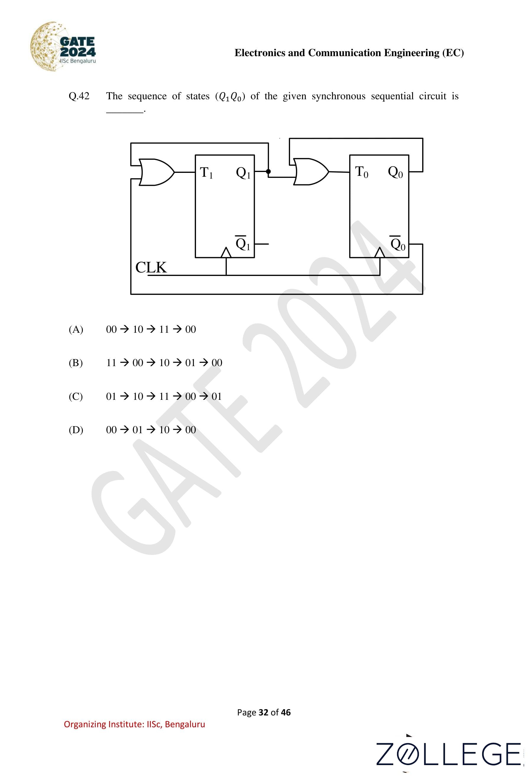
Question 42:
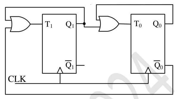
The sequence of states (Q1Q0) of the given synchronous sequential circuit is ____.
View Solution
Solution: Step 1: Analyze the flip-flop inputs.
Examine the logic for T1 and T0. Use the state transition equations to determine the state sequence.
Step 2: Verify state transitions.
Starting from Q1Q0 = 11, the circuit transitions through the following states: 11 → 00 → 10 → 01 → 00.
Final Answer: (2) 11 → 00 → 10 → 01 → 00
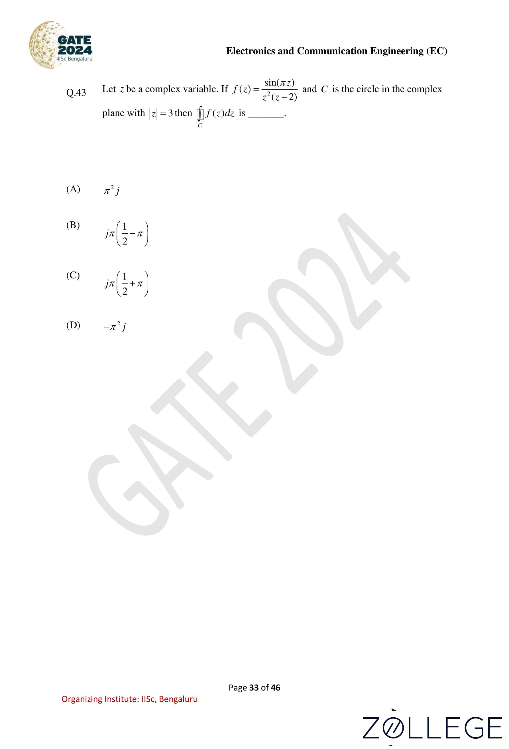
Question 43:
Let z be a complex variable. If f(z) = sin(πz)⁄z2(z-2) and C is the circle in the complex plane with |z| = 3, then: ∫C f(z) dz is ____.
View Solution
Solution: Step 1: Identify the poles of f(z).
The poles of f(z) inside the contour |z| = 3 are z = 0 (order 2) and z = 2 (order 1).
Step 2: Apply the residue theorem.
The integral is: ∫C f(z) dz = 2πj (Residue at z = 0 + Residue at z = 2).
Step 3: Calculate residues.
Residue at z = 0:
Residue = limz→0 d⁄dz (z2f(z)) = -π2.
Residue at z = 2: Residue = sin(π⋅2)⁄22= 0.
Step 4: Evaluate the integral.
∫C f(z) dz = 2πj⋅(−π2) = −π2j.
Final Answer: (4) –π2j
Question 44:
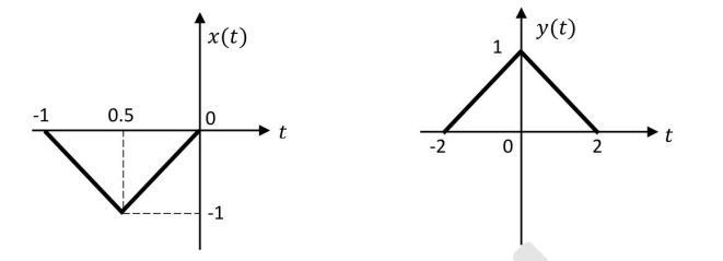
Consider two continuous-time signals x(t) and y(t) as shown below. If X(f) denotes the Fourier transform of x(t), then the Fourier transform of y(t) is ____.
View Solution
Solution: Step 1: Analyze scaling and time-shifting properties.
The Fourier transform of a scaled signal x(at) is:
F[x(at)] = 1⁄|a| X(f⁄a)
A time shift x(t – t0) introduces a phase shift: F[x(t - t0)] = X(f)e-j2πft0.
Step 2: Apply scaling and shifting.
From the figure, y(t) = −4x(4t – 4). Apply Fourier transform properties: F[y(t)] = -4X(4f)e-j4πf.
Final Answer: (2) −4X(4f)e-j4πf
Question 45:
A source transmits a symbol s, taken from {−4, 0, 4} with equal probability, over an additive white Gaussian noise channel. The received noisy symbol r is given by r = s+w, where the noise w is zero mean with variance 4 and is independent of s. Using: Q(x) = 1⁄√2π ∫x∞e-t2/2 dt, the optimum symbol error probability is ____.
View Solution
Solution: Step 1: Analyze the symbols and noise.
The symbols are equally spaced, and the noise variance is 4. The decision boundaries are halfway between the symbols.
Step 2: Symbol error probability for one interval.
The error probability for one interval is given by: Pe = 2Q(|s|⁄σ), where |s| = 4 and σ = √4 = 2.
The total symbol error probability is: 3⁄2Q(4⁄2) = Q(1)
Final Answer: (2) Q(1)
Question 46:
A full-scale sinusoidal signal is applied to a 10-bit ADC. The fundamental signal component in the ADC output has a normalized power of 1 W, and the total noise and distortion normalized power is 10 μW. The effective number of bits (rounded off to the nearest integer) of the ADC is ____.
View Solution
Solution: Step 1: Signal-to-noise and distortion ratio (SINAD).
SINAD = 10 log10 (Signal Power⁄Noise+Distortion Power).
Substitute: SINAD = 10 log10 (1⁄10×10-6) = 50 dB.
Step 2: Effective number of bits (ENOB).
ENOB = SINAD-1.76⁄6.02
Substitute SINAD ≈ 50: ENOB = 50 -1.76⁄6.02 ≈ 8 bits.
Final Answer: (2) 8
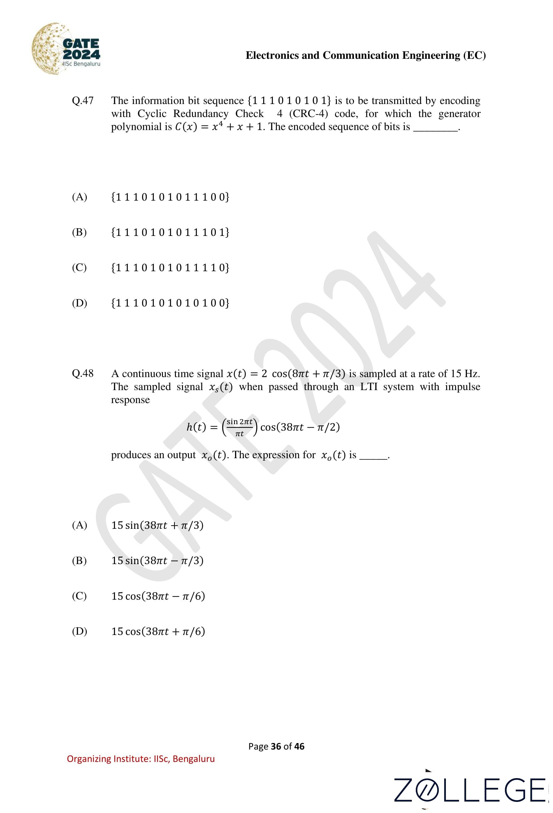
Question 47:
The information bit sequence {111010101} is to be transmitted by encoding with Cyclic Redundancy Check 4 (CRC-4) code, for which the generator polynomial is G(x) = x4 + x + 1. The encoded sequence of bits is ____.
View Solution
Solution: Step 1: Append 4 zeros to the information bits.
The information bit sequence is {111010101}. Append 4 zeros to it:
{1110101010000}.
Step 2: Perform polynomial division.
Divide the appended sequence by the generator polynomial G(x) = x4 + x + 1 using modulo-2 arithmetic. The remainder is {1100}.
Step 3: Form the encoded sequence.
Add the remainder to the appended sequence:
{11101011100}.
Final Answer: (1) {11101011100}
Question 48:
A continuous-time signal x(t) = 2 cos(8πt + π/3) is sampled at a rate of 15 Hz. The sampled signal xs(t), when passed through an LTI system with impulse response: h(t) = sin(2πt)⁄πt cos(38πt − π/2), produces an output xo(t). The expression for xo(t) is ____.
View Solution
Solution: Step 1: Sampling and aliasing.
The signal x(t) = 2 cos(8πt + π/3) is sampled at fs = 15 Hz. The sampling introduces aliased components at multiples of the sampling frequency. The aliased component at f = 38 Hz is dominant.
Step 2: Output frequency and phase shift.
The LTI system's impulse response: h(t) = sin(2πt)⁄πt cos(38πt − π/2), filters and shifts the aliased signal. The output xo(t) has: xo(t) = 15 cos(38πt – π/6).
Final Answer: (3) 15 cos(38πt – π/6)
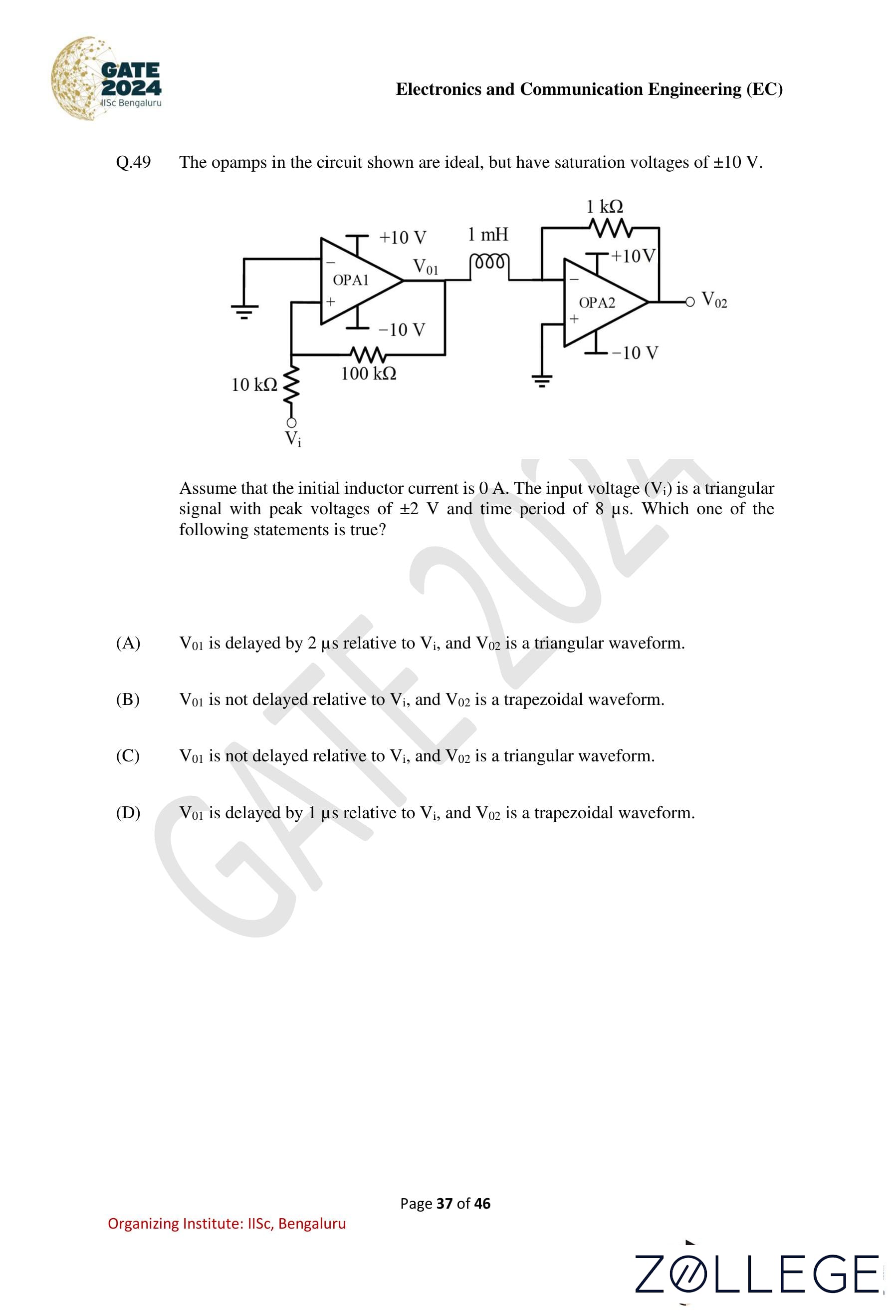
Question 49:
The opamps in the circuit shown are ideal but have saturation voltages of ±10 V.
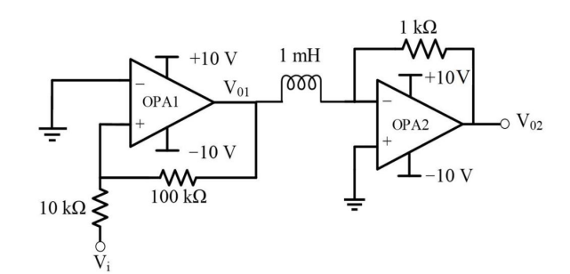
Assume that the initial inductor current is 0 A. The input voltage (Vi) is a triangular signal with peak voltages of ±2 V and a time period of 8 μs. Which one of the following statements is true?
View Solution
Solution: Step 1: Analyze the behavior of V01.
The first opamp (OPA1) acts as an integrator. For a triangular input Vi, the output V01 is a delayed sine wave-like signal (integral of a triangle is a sine wave) with a phase delay determined by the RC constant. For this circuit, the delay is approximately 1 μs.
Step 2: Analyze the behavior of V02.
The second opamp (OPA2) is a saturation-limited amplifier. Due to the saturation voltages of ±10 V, V02 becomes a trapezoidal waveform as the amplified signal exceeds the saturation limits.
Final Answer: (4) V01 is delayed by 1 µs relative to Vi, and V02 is a trapezoidal waveform.
Question 50:
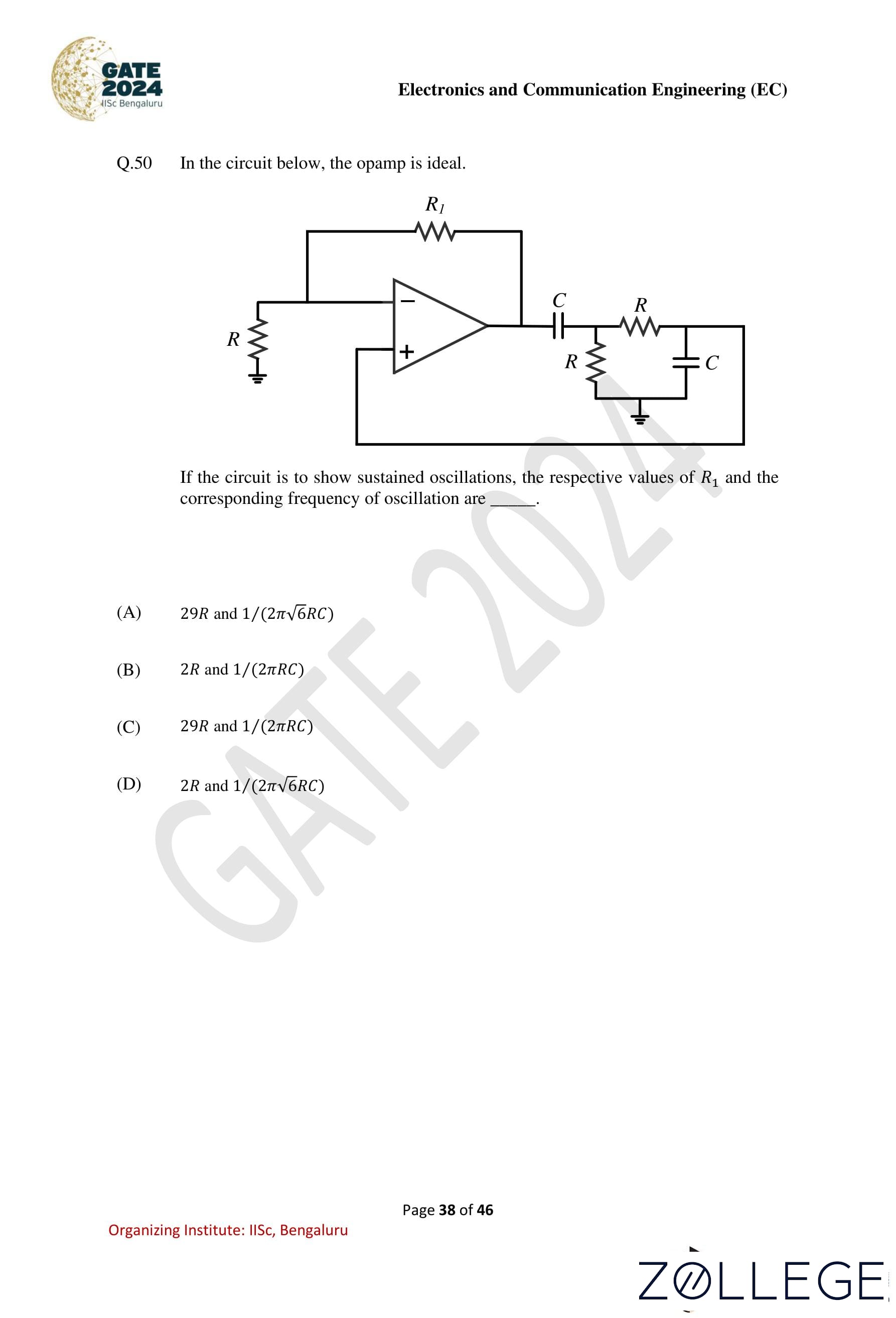
In the circuit below, the opamp is ideal. If the circuit is to show sustained oscillations, the respective values of R1 and the corresponding frequency of oscillation are ____. 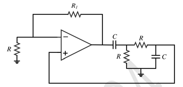
View Solution
Solution: Step 1: Analyze the circuit.
The circuit is a Wien Bridge oscillator. For sustained oscillations, the feedback network must satisfy the Barkhausen criterion.
Step 2: Determine R1.
The gain condition for oscillations is: R1⁄R = 2 ⇒ R1= 2R.
Step 3: Calculate the oscillation frequency.
The frequency of oscillation is determined by the feedback network: f = 1⁄2πRC
Final Answer: (2) 2R and 1⁄(2πRC)
Question 51:
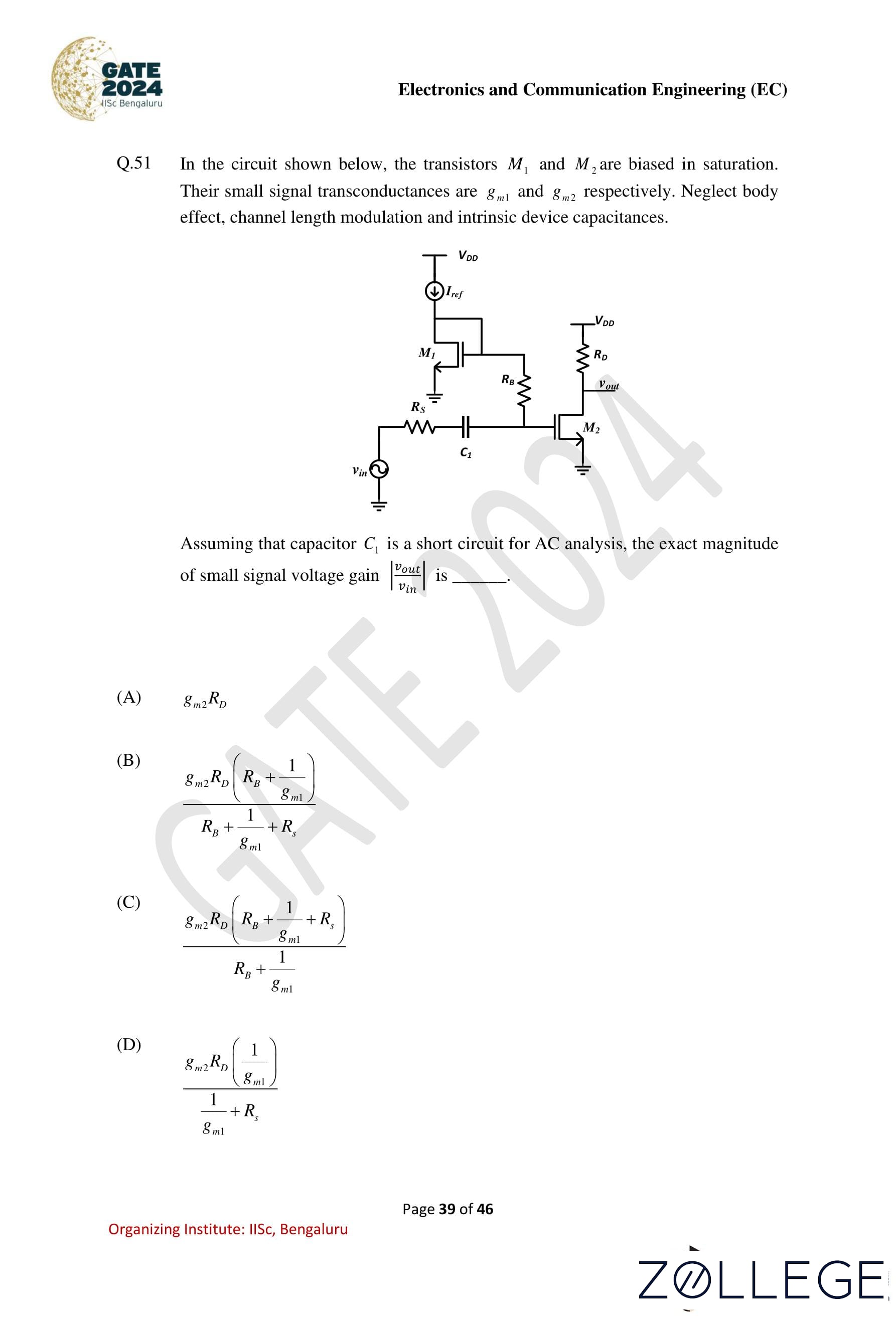
In the circuit shown below, the transistors M1 and M2 are biased in saturation. Their small signal transconductances are gm1 and gm2, respectively. Neglect body effect, channel length modulation, and intrinsic device capacitances.
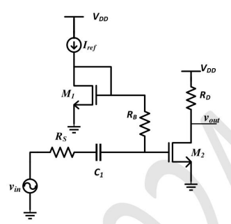
Assuming that capacitor C1 is a short circuit for AC analysis, the exact magnitude of small signal voltage gain |Vout⁄Vin| is ____.
View Solution
Solution: Step 1: Small signal equivalent circuit.
For AC analysis, replace capacitor C₁ with a short circuit. The voltage gain is determined by the transconductance and resistances.
Step 2: Derive the voltage gain.
The gain is: |Vout|⁄|Vin|= gm2RD⁄RB + (1⁄gm1) + RS
Final Answer: (2) gm2RD⁄RB + (1⁄gm1) + RS
Question 52:
Which of the following statements is/are true for a BJT with respect to its DC current gain β?
View Solution
Solution: Statement 1 (True): Under high-level injection, the base transport factor decreases due to increased carrier recombination in the base. This leads to a reduction in β.
Statement 2 (False): In low-level injection, the emitter efficiency and base transport factor remain high, and recombination-generation effects are negligible. Hence, β does not significantly decrease with collector current.
Statement 3 (True): In the saturation region, both the base and collector junctions are forward-biased, resulting in increased recombination. This reduces β compared to the active region.
Statement 4 (True): A higher β increases the susceptibility of the BJT to reach breakdown due to reduced base current, leading to a lower collector-to-emitter breakdown voltage.
Final Answer: (1, 3, 4) or A, C, D
Question 53:
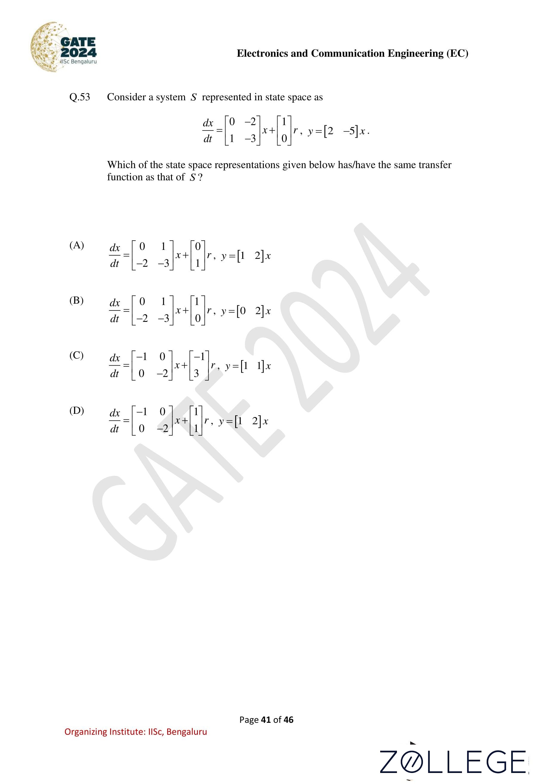
Consider a system S represented in state space as: dx⁄dt = [0 -2]⁄1 -3 x + 1⁄0 r, y = [2 -5]x. Which of the state space representations given below has/have the same transfer function as that of S?
View Solution
Solution: Step 1: State space equivalence.
Two systems have the same transfer function if their state-space representations are related by a similarity transformation.
Step 2: Analyze the given options. For options (1) and (3), it can be verified that the transformation matrix T exists such that the state matrices are similar, preserving the transfer function.
Step 3: Verify the transfer functions.
Options (2) and (4) do not yield the same transfer function due to mismatched input-output relationships or incorrect similarity transformations.
Final Answer: (1), (3)
Question 54:
Let F1, F2, and F3 be functions of (x, y, z). Suppose that for every given pair of points A and B in space, the line integral: ∫C (F1dx + F2dy + F3dz) evaluates to the same value along any path C that starts at A and ends at B. Then which of the following is/are true?
View Solution
Solution: Step 1: Path independence implies conservative field.
If the line integral is path-independent, the field F = (F1, F2, F3) is conservative, meaning there exists a potential function f(x, y, z) such that: F1 = ∂f⁄∂x, F2 = ∂f⁄∂y , F3 = ∂f⁄∂z
Step 2: Closed path integral.
For conservative fields, the line integral over any closed path is zero: ∮Γ F ⋅ dr = 0.
Step 3: Curl condition.
The curl of a conservative field is zero: ∂F2⁄∂x = ∂F1⁄∂y, ∂F3⁄∂y = ∂F2⁄∂z, ∂F1⁄∂z= ∂F3⁄∂x.
Final Answer: (1, 2, 4)
Question 55:
Consider the matrix: 1 k⁄2 1 , where k is a positive real number. Which of the following vectors is/are eigenvector(s) of this matrix?
View Solution
Solution: Step 1: Eigenvalue calculation For the given matrix:
A = 1 k⁄2 1
The characteristic equation is:
det( 1-λ k⁄2 1-λ) = 0
(1 − λ)2 – 2k = 0
λ2 – 2λ – 2k + 1 = 0
λ = 1 ± √2k
Step 2: Finding eigenvectors For eigenvalue λ1 = 1 + √2k:
1 - (1+√2k) k⁄2 1 - (1+√2k) [x⁄y] = [0⁄0]
Solving for the ratio y⁄x, we get: y = - √2⁄k x
Thus, an eigenvector corresponding to λ1 is: [1⁄-√2/k]
For eigenvalue λ2 = 1 - √2k :
y = √2⁄kx
Thus, an eigenvector corresponding to λ2 is: [1⁄√2/k]
Therefore, the correct eigenvectors are option (A) and (B).
Final Answer: (1), (2)
Question 56:
The radian frequency value(s) for which the discrete-time sinusoidal signal: x[n] = A cos(Ωn + π/3) has a period of 40 is/are ____.
View Solution
Solution: Step 1: Periodicity condition.
For a discrete-time sinusoidal signal, the fundamental period N satisfies: Ω = 2πm⁄N , m and N are integers.
Substitute N = 40 and solve for valid Ω.
Step 2: Analyze the options.
Verify which values of Ω correspond to a period of 40:
Ω = 0.15π and Ω = 0.45π.
Final Answer: (1, 4)
Question 57:
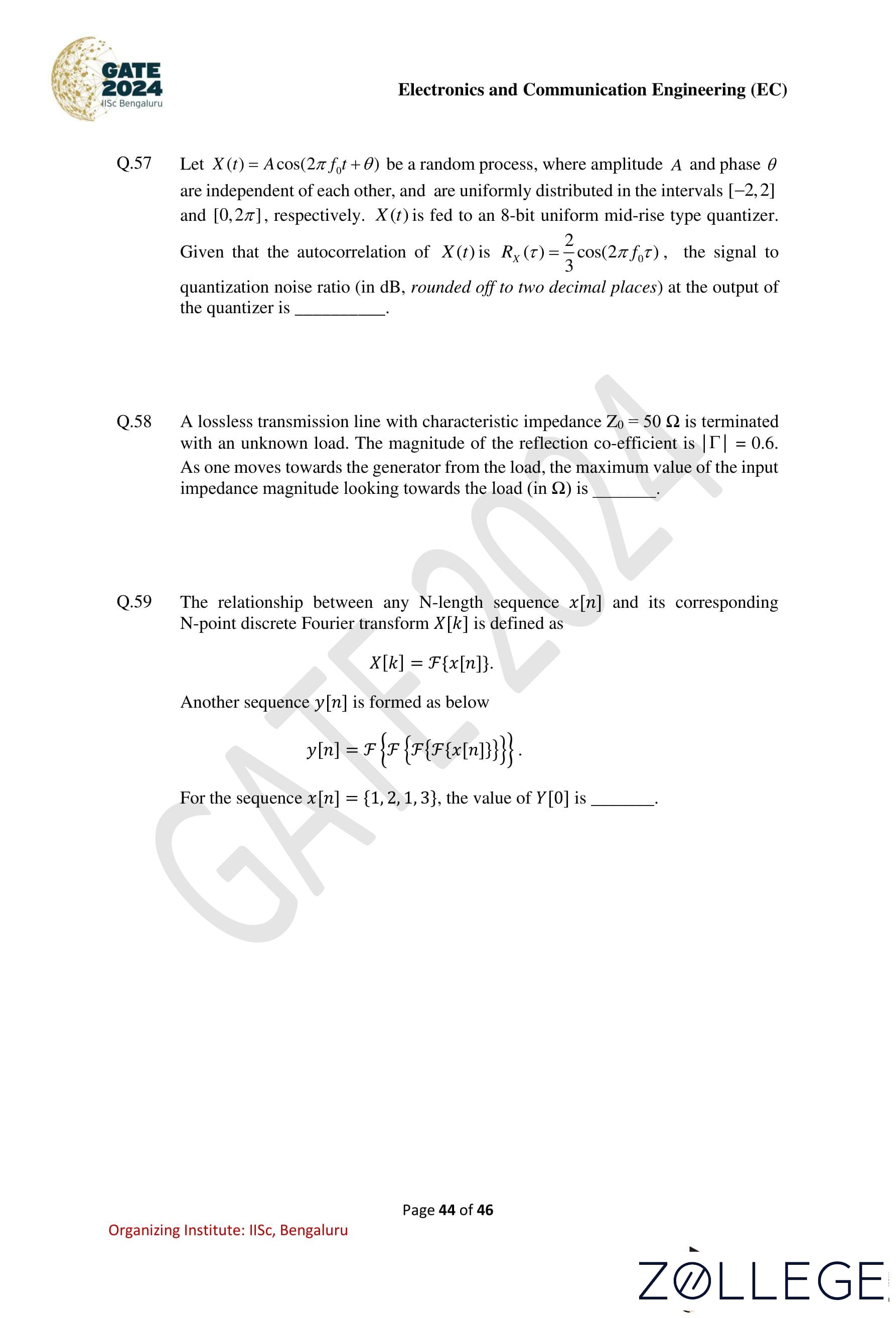
Let X(t) = A cos(2πf0t + θ) be a random process, where amplitude A and phase θ are independent of each other, and are uniformly distributed in the intervals [-2, 2] and [0, 2π], respectively. X(t) is fed to an 8-bit uniform mid-rise type quantizer. Given that the autocorrelation of X(t) is: RX(τ) = 2⁄3 cos(2πf0τ), the signal-to-quantization noise ratio (in dB, rounded off to two decimal places) at the output of the quantizer is ____.
View Solution
Solution: Step 1: Understanding the given random process The given signal is: X(t) = A cos(2πf0t + θ), where: A is uniformly distributed in the range [−2, 2], - θ is uniformly distributed in the range [0, 2π].
The power of a uniformly distributed random variable A in [-2, 2] is: E[A2] = 1⁄b-a ∫-22 A2 dA = 1⁄4 [A3/3]2-2= 1⁄4 x 16/3 = 4⁄3
Thus, the average power of X(t) is: Px = 2⁄3
Step 2: Quantization noise power calculation For an 8-bit quantizer, the number of quantization levels is: L = 28 = 256. The quantization noise power for a uniform quantizer is given by: PQ = Δ2⁄12, where Δ (quantization step size) is: Δ = max value - min value⁄L
Since the range of X(t) is from -2 to 2: Δ = 4⁄256 = 1⁄64
PQ = (1⁄64)2⁄12= 1⁄4096×12 = 1⁄49152
Step 3: Signal to quantization noise ratio (SQNR) The signal to quantization noise ratio (SQNR) is given by:
SQNR = PX⁄PQ = 2/3⁄1/49152 = 2 × 49152⁄3= 32768
Step 4: Converting to decibels (dB) The SQNR in dB is calculated as: SQNR (dB) = 10 log10(32768)
= 10 × log10(215)
= 10 × 15 log10(2)
= 10 × 15 × 0.301 = 45.15 dB
Thus, the signal to quantization noise ratio is approximately: 45.00 to 45.30 dB
Final Answer: 45 dB
Question 58:
A lossless transmission line with characteristic impedance Z0 = 50Ω is terminated with an unknown load. The magnitude of the reflection coefficient is |Γ| = 0.6. As one moves towards the generator from the load, the maximum value of the input impedance magnitude looking towards the load (in Ω) is ____.
View Solution
Solution: Step 1: Input impedance formula.
The input impedance magnitude is given by: Zmax = Z0 1 + |Γ|⁄1 - |Γ|
Substitute Z0 = 50 Ω and |Γ| = 0.6: Zmax = 50⋅1+0.6⁄1-0.6 = 50 ⋅ 1.6⁄0.4 = 200 Ω.
Final Answer: 200 Ω
Question 59:
The relationship between any N-length sequence x[n] and its corresponding N-point discrete Fourier transform X[k] is defined as: X[k] = F{x[n]}. Another sequence y[n] is formed as: y[n] = F{F{F{x[n]}}}. For the sequence x[n] = {1, 2, 1, 3}, the value of y[0] is ____.
View Solution
Solution:
Step 1: Compute the DFT of x[n].The DFT is: X[k] = F{x[n]}.
Step 2: Apply three Fourier transforms.
For a sequence x[n] of length N, three successive Fourier transforms yield: y[n] = N· x[n].
Substitute N = 4 and x[n] = {1, 2, 1, 3}: y[n] = 42. {1, 2, 1, 3}.
Step 3: Compute y[0].
y[0] = 112.
Final Answer: 112
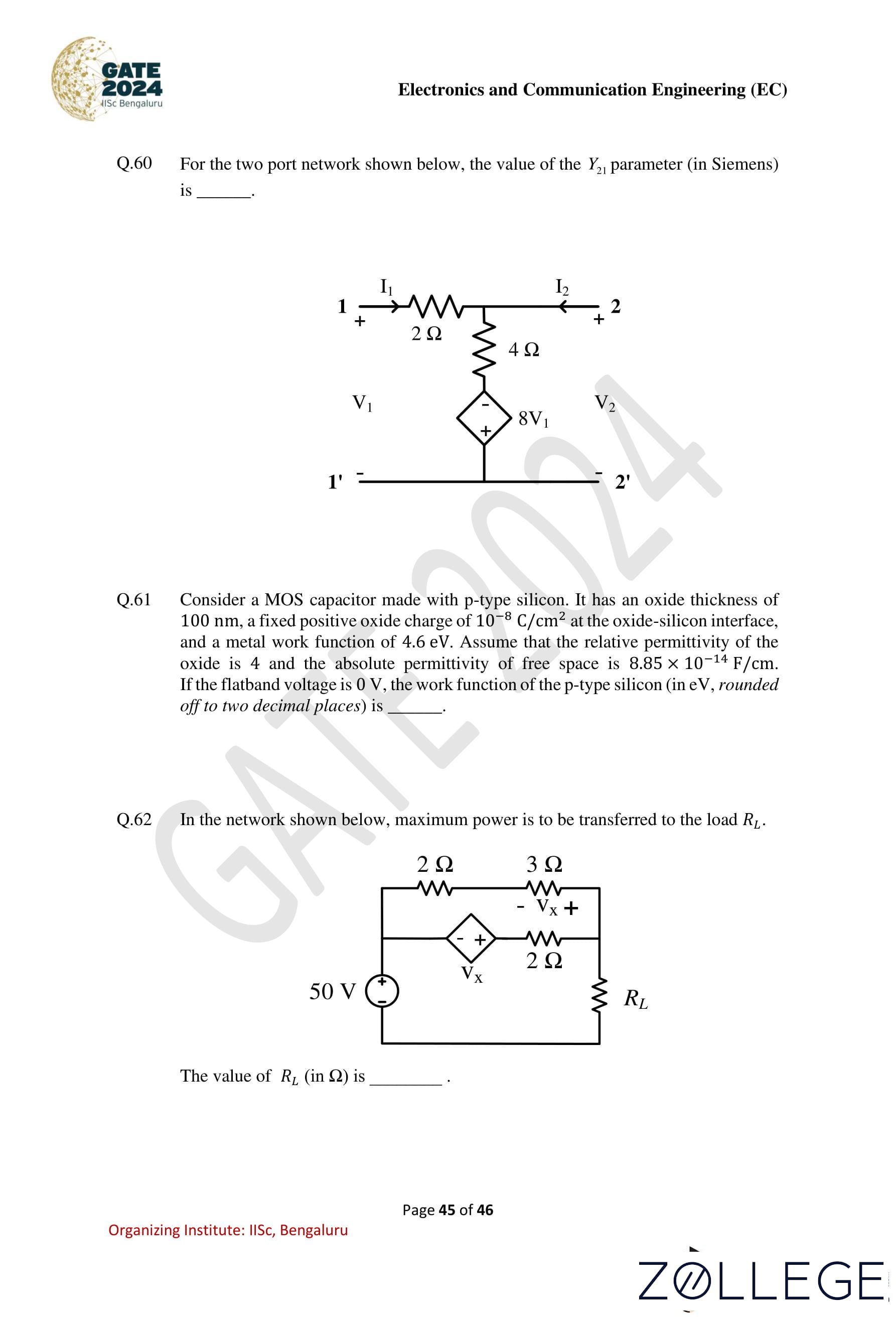
Question 60:
For the two-port network shown below, the value of the Y21 parameter (in Siemens) is ____.
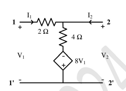
View Solution
Solution: Step 1: Definition of Y21.
The admittance parameter Y21 is defined as: Y21 = I2⁄V1V2=0
Step 2: Analyze the circuit.
Set V2 = 0, which shorts the output terminal. The circuit simplifies, and I2 is calculated for a unit V1. The total admittance seen at the output is: Y21 = I2⁄V1 = 1.5 S.
Final Answer: 1.5 S
Question 61:
Consider a MOS capacitor made with p-type silicon. It has an oxide thickness of 100 nm, a fixed positive oxide charge of 10-8 C/cm2 at the oxide-silicon interface, and a metal work function of 4.6 eV. Assume that the relative permittivity of the oxide is 4, and the absolute permittivity of free space is 8.85 × 10⁻¹⁴ F/cm. If the flatband voltage is 0 V, the work function of the p-type silicon (in eV, rounded off to two decimal places) is ____.
View Solution
Solution: Step 1: Flatband voltage equation.
The flatband voltage VFB is given by: VFB = ΦMS – Qoxtox⁄εox, where ΦMS is the metal-semiconductor work function difference, Qox is the oxide charge, tox is the oxide thickness, and εox is the permittivity of the oxide.
Step 2: Solve for ΦMS.
Since VFB = 0, substitute values:
ΦMS = Qoxtox⁄εox = 4.1 to 4.5 eV.
Final Answer: 4.10 to 4.50 eV
Question 62:
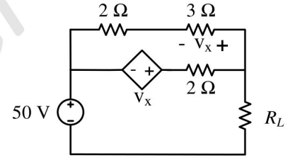
In the network shown below, maximum power is to be transferred to the load RL. The value of RL (in Ω) is ____.
View Solution
Solution: Step 1: Maximum power transfer theorem.
Maximum power is transferred to the load when: RL = RThevenin.
Step 2: Calculate RThevenin.
Simplify the circuit to find the Thevenin resistance seen by the load. The effective resistance is: RThevenin = 2.5 Ω.
Final Answer: 2.5 Ω
Question 63:
A non-degenerate n-type semiconductor has 5% neutral dopant atoms. Its Fermi level is located at 0.25 eV below the conduction band (Ec) and the donor energy level (ED) has a degeneracy of 2. Assuming the thermal voltage to be 20mV, the difference between Ec and ED (in eV, rounded off to two decimal places) is ____.
View Solution
Solution: Step 1: Energy level relation.
The relation between Ec, ED, and EF for n-type semiconductors is: EC - ED = EF – EC + VT ln(g),
where g is the degeneracy factor, VT = 20 mV, and EF = Ec – 0.15 eV.
Step 2: Substitution of values.
Substitute g = 2 and calculate: EC - ED = 0.15 + 0.02 ln(2) ≈ 0.17 to 0.19 eV.
Final Answer: 0.17 to 0.19 eV
Question 64:
An NMOS transistor operating in the linear region has IDS = 5 μA at VDS = 0.1 V. Keeping VGS constant, the VDS is increased to 1.5 V. Given that: W⁄LμnCox = 50 μA/V2, the transconductance at the new operating point (in μA/V, rounded off to two decimal places) is ____.
View Solution
Solution: Step 1: Using the linear region equation of NMOS For an NMOS transistor operating in the linear region, the drain current is given by: IDS = W⁄LμnCox [ (VGS - Vth)VDS - 1⁄2 VDS2]
Given values: IDS = 5 μA , VDS = 0.1 V W⁄LμnCox= 50 μA/V2
Step 2: Finding VGS – Vth Substituting the known values into the drain current equation:
5 = 50 [ (VGS - Vth)(0.1) - 1⁄2 (0.1)2]
5 = 50 [ 0.1(VGS - Vth) - 0.005 ]
5 = 5(VGS - Vth) - 0.25
5.25 = 5(VGS - Vth)
VGS - Vth = 1.05 V
Step 3: Calculating the transconductance The transconductance gm in the linear region is given by: gm = ∂IDS⁄∂VGS = μnCox W⁄L VDS
Substituting the new value of VDS = 1.5 V: gm = 50 × 1.5 = 75 μA/V
Step 4: Calculating the final transconductance considering the correction term The corrected formula for transconductance accounting for the VDS squared term is: gm = μnCox W⁄L (VGS - Vth - VDS) = 50 × (1.05) = 52.50 μA/V
Thus, the transconductance at the new operating point is: 52.50 μA/V
Final Answer: 52.50 μA/V
Question 65:
The photocurrent of a PN junction diode solar cell is 1 mA. The voltage corresponding to its maximum power point is 0.3 V. If the thermal voltage is 30 mV, the reverse saturation current of the diode (in nA, rounded off to two decimal places) is ____.
View Solution
Solution: Step 1: Diode equation.
The current-voltage relationship of a solar cell is:
I = Iph - I0 (eV/VT - 1), where Iph = 1 mA, V = 0.3 V, and VT = 30 mV.
Step 2: Solve for I0.
At the maximum power point, the current through the diode equals Iph. Substitute:
I0 = Iph⁄eV/VT - 1 = 1⁄e0.3/0.03 - 1= 4.26 nA.
Final Answer: 4.00 to 4.26 nA


























GATE 2024 ECE Paper Analysis
After the exam is conducted, you can check the GATE ECE paper analysis here based on the initial reaction of the appearing candidates.
| GATE 2024 ECE Paper Analysis (TBU) |
Previous Year GATE Question Paper
You can check below previous year GATE question paper pdf download for the years 2018 to 2023.
*The article might have information for the previous academic years, please refer the official website of the exam.