
GATE 2024 Chemical Engineering Question Paper Pdf - Check Solutions with Answer Key Pdf
- Chemistry Syllabus
- Maths Syllabus
- Physics Syllabus
- Exam Pattern
- Paper Analysis
- Chemical Engg Syllabus
- Civil Engg Syllabus
- ECE Syllabus
- Mechanical Engg Syllabus
- Engg Science Syllabus
- Mining Engg Syllabus
- IN Syllabus
- CSE Syllabus
- EE Syllabus
- AE Syllabus
- BM Syllabus
- GG Syllabus
- EY Syllabus
- ST Syllabus
- TF Syllaus
- AR Syllabus
- XL Syllabus
- MT Syllabus
- PI Syllabus
- PE Syllabus
- ME Pattern
- TF Pattern
- CE Pattern
- EE Pattern
- EC Pattern
- CS Pattern
- BT Pattern
- BM Pattern
- IN Pattern
- DA Syllabus
- NA & ME Syallabus
- ES & Engg Syllabus
- Geomatics Engg Syllabus
- Agri Engg Syllabus
- Humanities and Social Sci
- PI Syllabus

.jpg?tr=h-55,w-55,c-force)
Content Strategist|Tech-innovator|National Hackathon Winner | Updated On - Jan 27, 2025
GATE 2024 Electrical Engineering Question Paper is available for download. The exam was successfully conducted by IISc/IITs on February 11 in the afternoon session from 2:30 PM to 5:30 PM. As per the student’s initial reactions, the GATE 2024 Electrical Engineering Question Paper was reported as Moderate. The Mathematics section in the GATE 2024 Electrical Engineering Question Paper was reported as Challenging, Core Electrical Engineering as Moderate to Difficult, and General Aptitude as Easy to Moderate.
GATE 2024 Electrical Engineering Question Paper with Answer Key PDF
| GATE 2024 Electrical Engineering February 4 Question Paper with Answer Key |  Download Download |
Check Solution |
GATE Electrical Engineering 2024 Questions with Solutions
GENERAL APTITUDE
Question 1:
If ‘→’ denotes increasing order of intensity, then the meaning of the words [talk → shout → scream] is analogous to [please → → pander]. Which one of the given options is appropriate to fill the blank?
View Solution
Step 1: Analyzing the given pattern. If → denotes increasing order of intensity:
[Talk → Shout → Scream]
The analogous pattern is:
[Please → → Pander]
Step 2: Evaluating options.
Option (1) flatter: To praise someone to make them feel attractive or important. This matches the intensity increase.
Option (2) flutter: To move quickly and lightly, unrelated to the context.
Option (3) fritter: To waste time or resources, not suitable.
Option (4) frizzle: To make something crisp or burn lightly, unrelated.
Conclusion: Hence, the correct option is (1) flatter.
Question 2:
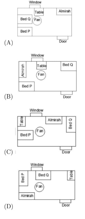
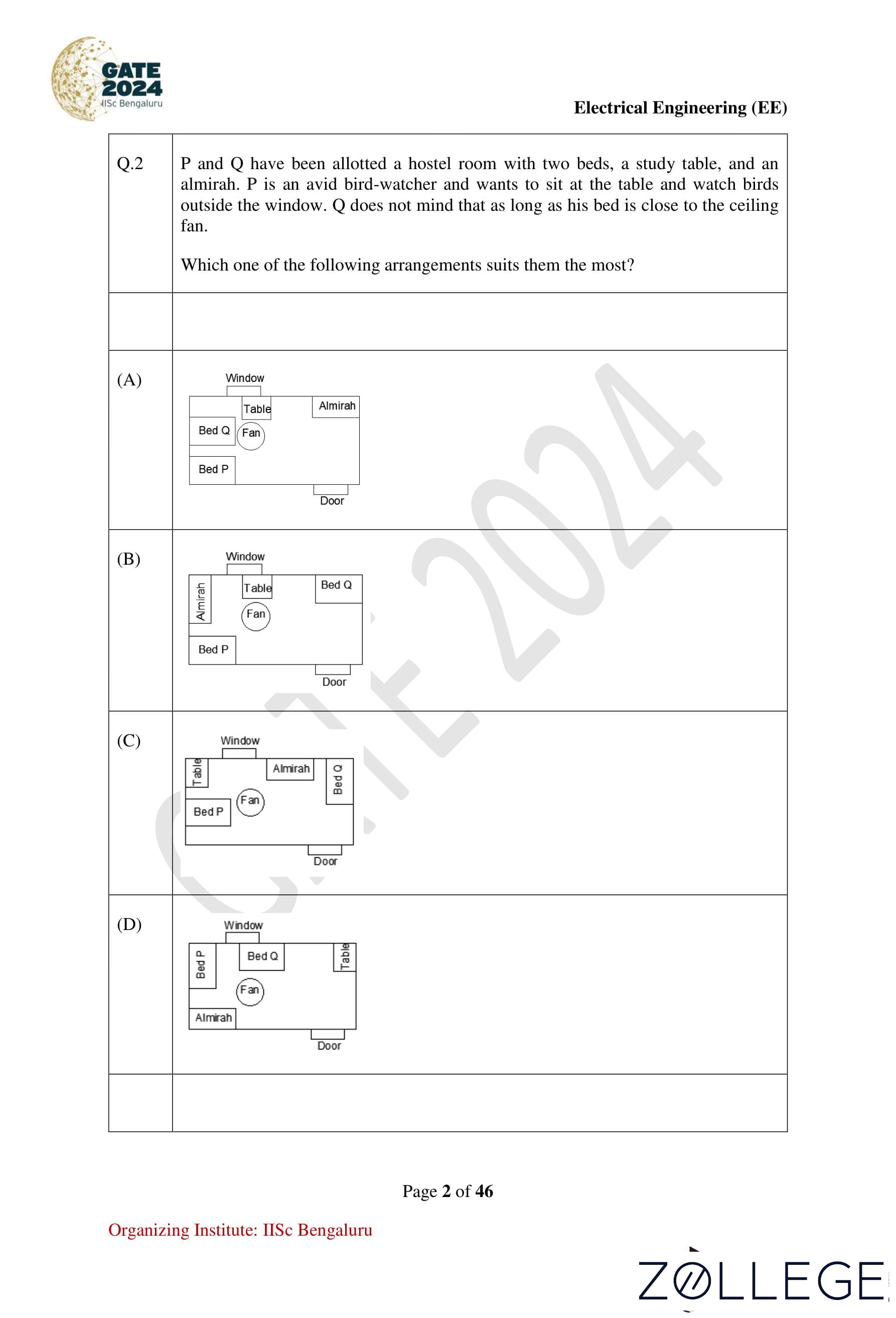
P and Q have been allotted a hostel room with two beds, a study table, and an almirah. P is an avid birdwatcher and wants to sit at the table and watch birds outside the window. Q prefers a bed close to the ceiling fan. Which one of the following arrangements suits them the most?

View Solution
Step 1: Understanding the preferences.
Given:
- Two beds
- A study table
- An almirah
P:Wants to sit at the table near the window.Q:Wants a bed close to the ceiling fan.
Step 2: Evaluating the arrangements.
Option 1 satisfies:
- P has access to the table near the window.
- Q’s bed is closest to the ceiling fan.
Conclusion: Hence, the correct option is 1.
Question 3:
The decimal number system uses the characters 0, 1, 2, ..., 8, 9, and the octal number system uses the characters 0, 1, 2, ..., 6, 7. For example, the decimal number 12 (= 1 × 101 + 2 × 100) is expressed as 14 (= 1 × 81 + 4 × 80) in the octal number system. The decimal number 108 in the octal number system is:
View Solution
Step 1: Decimal to octal conversion using division by 8.
Convert Decimal to Binary:
- Divide the number by 2.
- Get the integer quotient for the next iteration.
- Get the remainder for the binary digit.
- Repeat the above steps until the quotient is equal to 0.
Given: Decimal Number = 108
10810 ⇒ Binary Conversion Steps:
| Quotient | Remainder (Binary Digit) |
|---|---|
| 108 ÷ 2 = 54 | 0 |
| 54 ÷ 2 = 27 | 0 |
| 27 ÷ 2 = 13 | 1 |
| 13 ÷ 2 = 6 | 1 |
| 6 ÷ 2 = 3 | 0 |
| 3 ÷ 2 = 1 | 1 |
| 1 ÷ 2 = 0 | 1 |
Thus, 10810 = (1101100)2.
Step 2: Convert Binary to Octal.
Group the binary digits into sets of three from right to left: (001 101 100)2
Convert each group into octal:
- (001)2 = 1
- (101)2 = 5
- (100)2 = 4
Thus, (1101100)2 = (154)8.
Verification:
1 × 82 + 5 × 81 + 4 × 80 = 64 + 40 + 4 = 108.
Conclusion: Therefore, 154 is correct.
Question 4
A shopkeeper buys shirts from a producer and sells them at 20% profit. A customer has to pay Rs. 3186 including 18% taxes per shirt. At what price did the shopkeeper buy each shirt?
View Solution
Step 1: Relating selling price and cost price.
Profit = S.P - C.P
Profit% = (S.P − C.P) / C.P
Profit%: 20% ⇒ S.P = C.P × 1.2
Step 2: Adjusting for tax.
Selling Price (with tax): 3186 = S.P × (118 / 100)
S.P = 3186 × (100 / 118) = 2700.
Step 3: Calculating cost price.
C.P = S.P / 1.2 = 2700 / 1.2 = 2250.
Conclusion: Hence, the correct option is 2250.
Question 5:
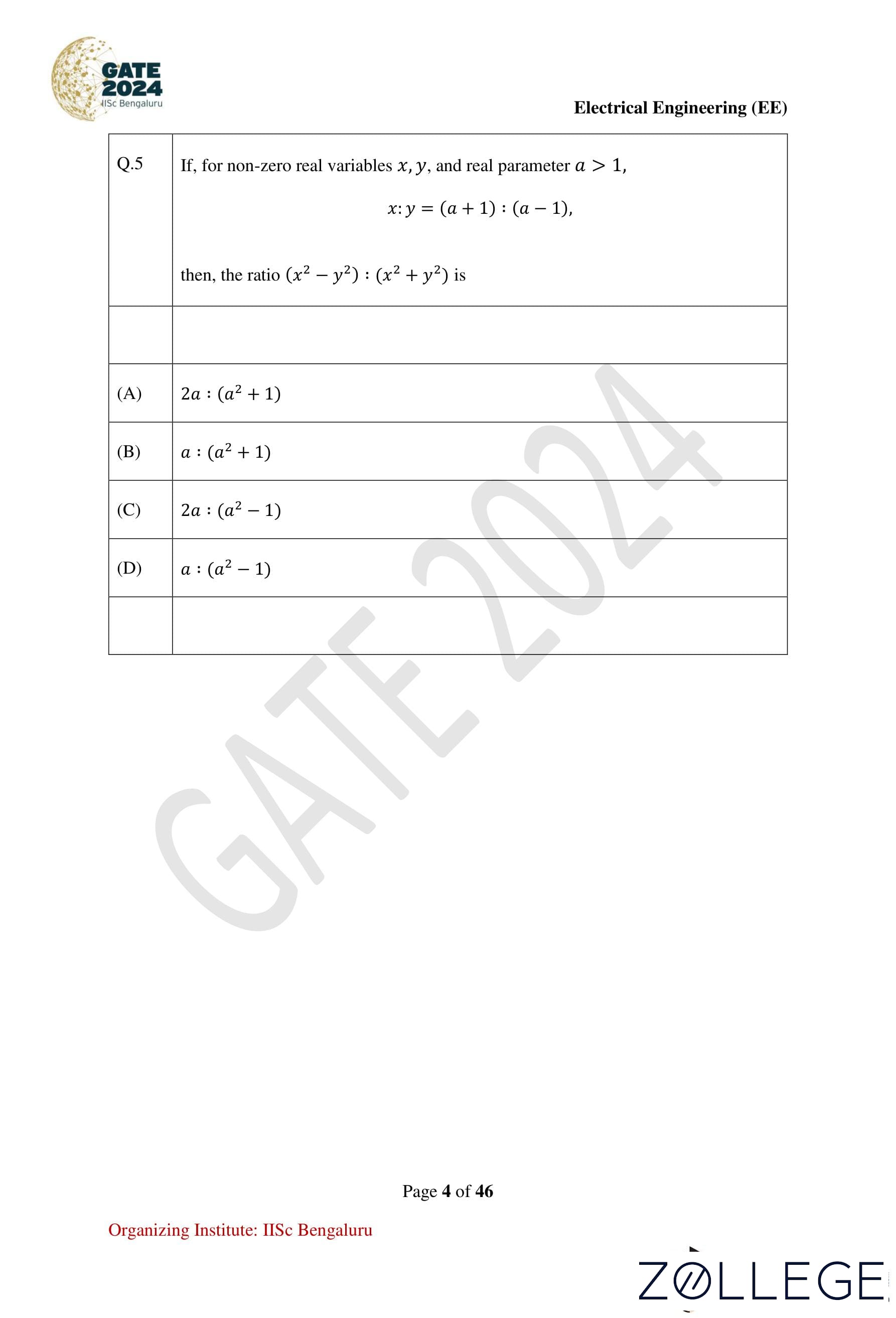
If, for non-zero real variables x, y and a real parameter a > 1, x : y = (a+1) : (a−1). Then, the ratio (x2 − y2) : (x2 + y2) is:
View Solution
Step 1: From the given condition, x : y = (a + 1) : (a − 1), we write:
x / y = (a + 1) / (a − 1).
Step 2: Substitute this into the ratio (x2 − y2) : (x2 + y2):
(x2 − y2) / (x2 + y2) = ((x / y)2 − 1) / ((x / y)2 + 1).
Step 3: Replace x / y with (a+1) / (a−1):
((a+1)/(a−1))2 − 1 / ((a+1)/(a−1))2 + 1 = ((a+1)2 − (a−1)2) / ((a+1)2 + (a−1)2).
Step 4: Expand and simplify:
(a + 1)2 − (a − 1)2 = 4a, (a + 1)2 + (a − 1)2 = 2a2 + 2.
Step 5: The required ratio is:
4a / (2a2 + 2) = 2a / (a2 + 1).
Conclusion: The correct option is 1 (2a : (a2 + 1)).
Question 6:
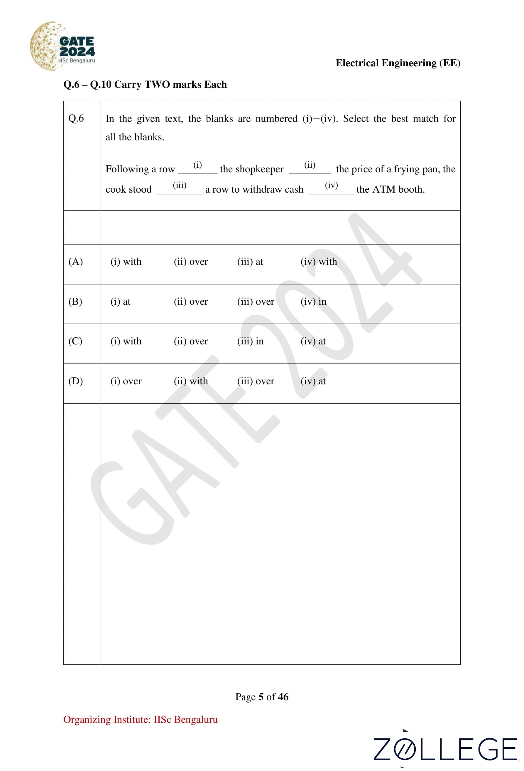
In the given text, the blanks are numbered (i)–(iv). Select the best match for all the blanks. Following a row (i) the shopkeeper (ii) the price of a frying pan, the cook stood (iii) a row to withdraw cash (iv) the ATM booth.
View Solution
Step 1: Analyze the context for each blank:
- (i) The row involves disagreement, hence "with".
- (ii) The shopkeeper’s control over the price suggests "over".
- (iii) A spatial location implies "in".
- (iv) A specific place requires "at".
Step 2: Substitute the correct prepositions into the sentence:
“Following a row with the shopkeeper over the price of a frying pan, the cook stood in a row to withdraw cash at the ATM booth.”
Conclusion: The correct option is 3 ((i) with, (ii) over, (iii) in, (iv) at).
Question 7:
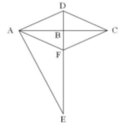
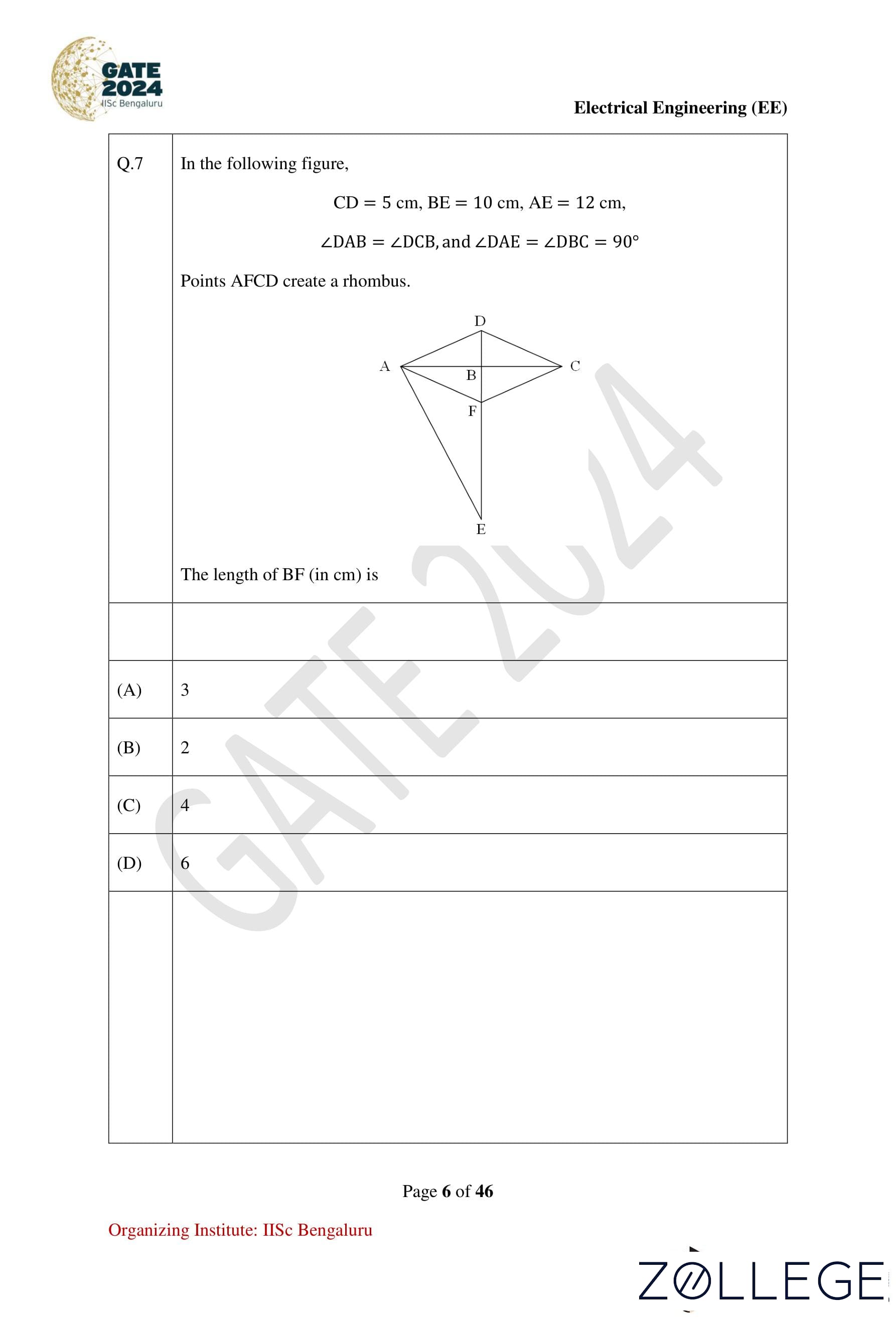
In the following figure, CD = 5 cm, BE = 10 cm, AE = 12 cm, ∠DAB = ∠DCB, and ∠DAE = ∠DBC = 90°. Points AFCD create a rhombus. The length of BF (in cm) is:
View Solution
Step 1: From the properties of the rhombus, diagonals intersect at 90°:
CD = AD = AF = FC = 5.
From provided question:
- CD = 5 cm
- AE = 12 cm
- BE = 10 cm
- ∠DAB = ∠DCB and ∠DAE = ∠DBC = 90° then ∠DBC = ∠DBA = ∠ABF = ∠FBC = 90°.
In △DAE:
(DE)2 = (DA)2 + (AE)2
DE = √((5)2 + (12)2) = √169 = 13 cm.
DE = DB + BE ⇒ DB = DE − BE.
DB = 13 − 10 = 3 cm.
Conclusion: The length of BF is 3 cm. Correct option: 1.
Question 8:
The chart below shows the data of the number of cars bought by Millennials and Gen X people in a country from the year 2010 to 2020 as well as the yearly fuel consumption of the country (in Million liters). Considering the data presented in the chart, which one of the following options is true?

View Solution
Step 1: Calculate the increase in the number of Millennial car buyers from 2010 to 2015:
Increase in Millennials = 45000 − 20000 = 25000.
Step 2: Calculate the decrease in the number of Gen X car buyers from 2010 to 2015:
Decrease in Gen X = 40000 − 30000 = 10000.
Step 3: Compare the values:
The increase in the number of Millennials (25000) is greater than the decrease in the number of Gen X (10000).
Conclusion: The correct option is 3.
Question 9:
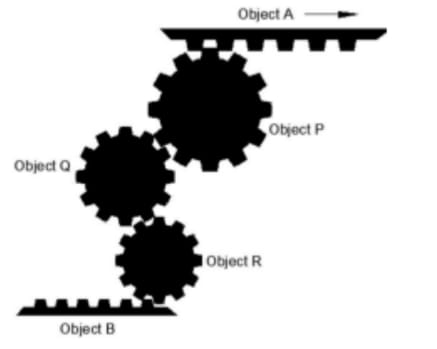
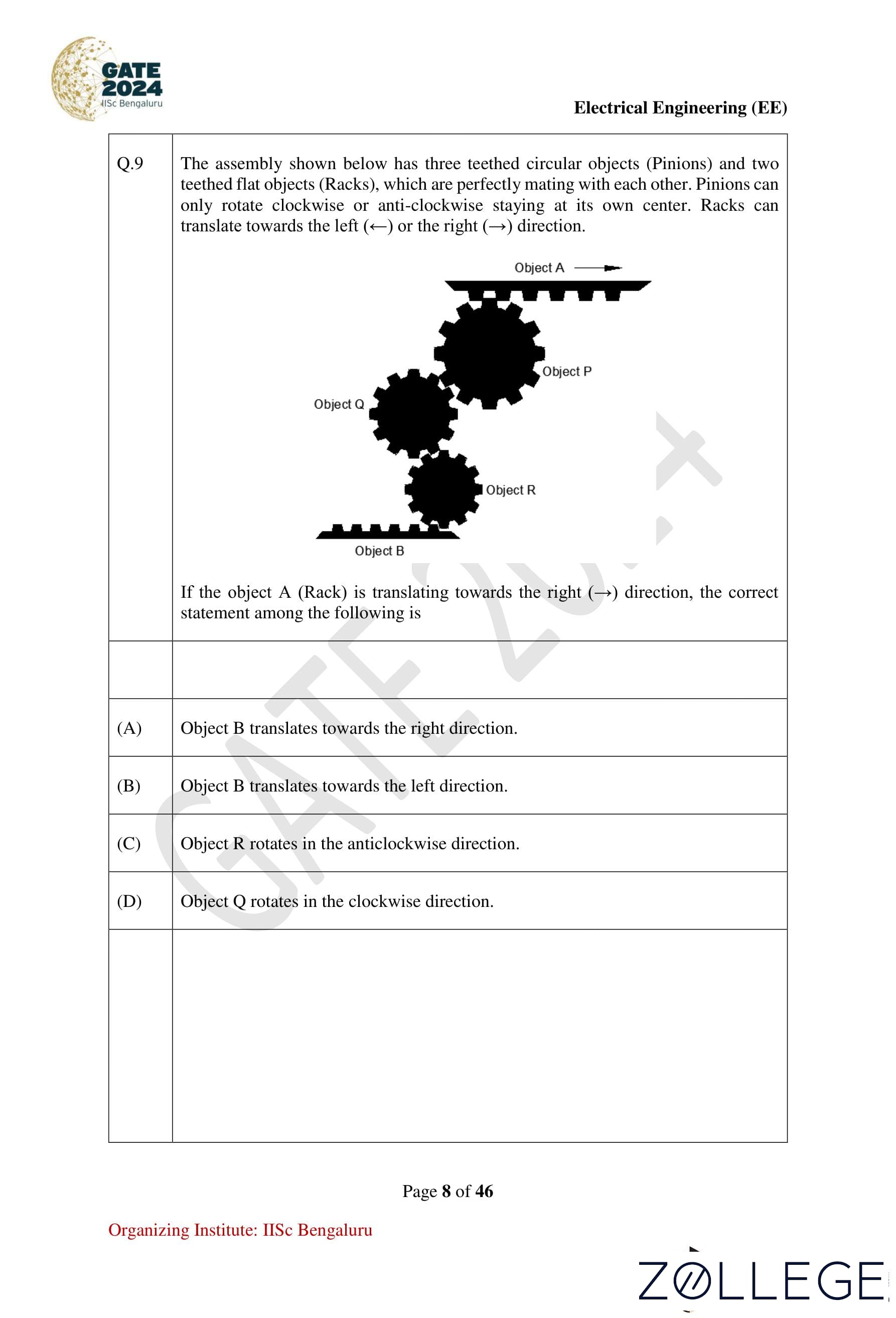
The assembly shown below has three teethed circular objects (Pinions) and two teethed flat objects (Racks), which are perfectly mating with each other. Pinions can only rotate clockwise or anti-clockwise staying at its own center. Racks can translate towards the left (←) or the right (→) direction. If the object A (Rack) is translating towards the right (→) direction, the correct statement among the following is:
View Solution
Step 1: Understanding the Mechanism
- Racks and Pinions: A rack is a linear gear with teeth, and a pinion is a circular gear. When the rack moves, it causes the connected pinion to rotate. The direction of rotation of the pinion is always opposite to the movement of the rack.
System Analysis:
- Object A moves to the right (→): This movement causes Object P (the pinion connected to it) to rotate clockwise.
- Object P rotates clockwise: As Object P is connected to a rack (Object B), its clockwise rotation drives Object B to move to the left (←).
- Object B moves to the left (←): The leftward movement of Object B makes Object Q rotate in an anticlockwise direction.
- Object Q rotates anticlockwise: Finally, the anticlockwise rotation of Object Q causes Object R to move to the right (→).
Conclusion: The correct option is 2 (Object B translates towards the left direction).
Question 10:
A surveyor has to measure the horizontal distance from her position to a distant reference point C. Using her position as the center, a 200 m horizontal line segment is drawn with the two endpoints A and B. Points A, B, and C are not collinear. Each of the angles ∠CAB and ∠CBA are measured as 87.8°. The distance (in m) of the reference point C from her position is nearest to:
View Solution
Step 1: Using the given data, the angles ∠CAB = ∠CBA = 87.8° and the base AB = 200 m.
Step 2: In △CAB, use the tangent function for small angles:
tan θ = cx / AB, where cx is the perpendicular from C.
Step 3: Substitute values:
tan(87.8°) = cx / 100.
Step 4: Solve for cx:
cx = 100 × tan(87.8°) = 2603 m.
Conclusion: The correct option is 1 (2603).
Electrical Engineering
Question 11:
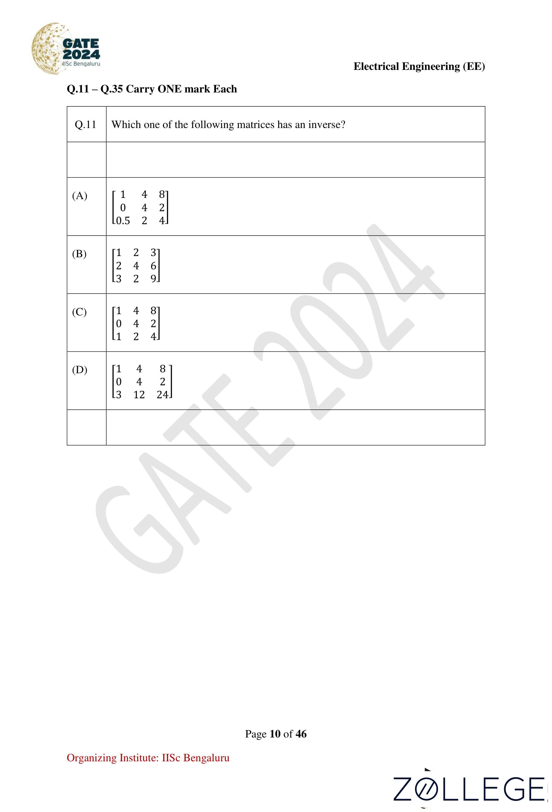
Which one of the following matrices has an inverse?
View Solution
Step 1: A matrix has an inverse if and only if its determinant is non-zero.
Step 2: Calculate the determinants of the matrices:
- For option (A): Applying row transformations, the determinant is 0 ⇒ Singular matrix.
- For option (B): The second row is a multiple of the first row, so determinant = 0 ⇒ Singular matrix.
- For option (C): Calculate determinant:
Determinant = 1(16 − 4) − 4(0 − 2) + 8(0 − 4)
= 1(12) − 4(2) + 8(−4)
= 12 − 8 − 32 = −28 ≠ 0 (Non-singular matrix).
- For option (D): Applying row transformations, the determinant is 0 ⇒ Singular matrix.
Step 3: Only matrix (C) is non-singular, and thus has an inverse.
Conclusion: The correct option is 3.
Question 12:
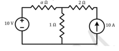
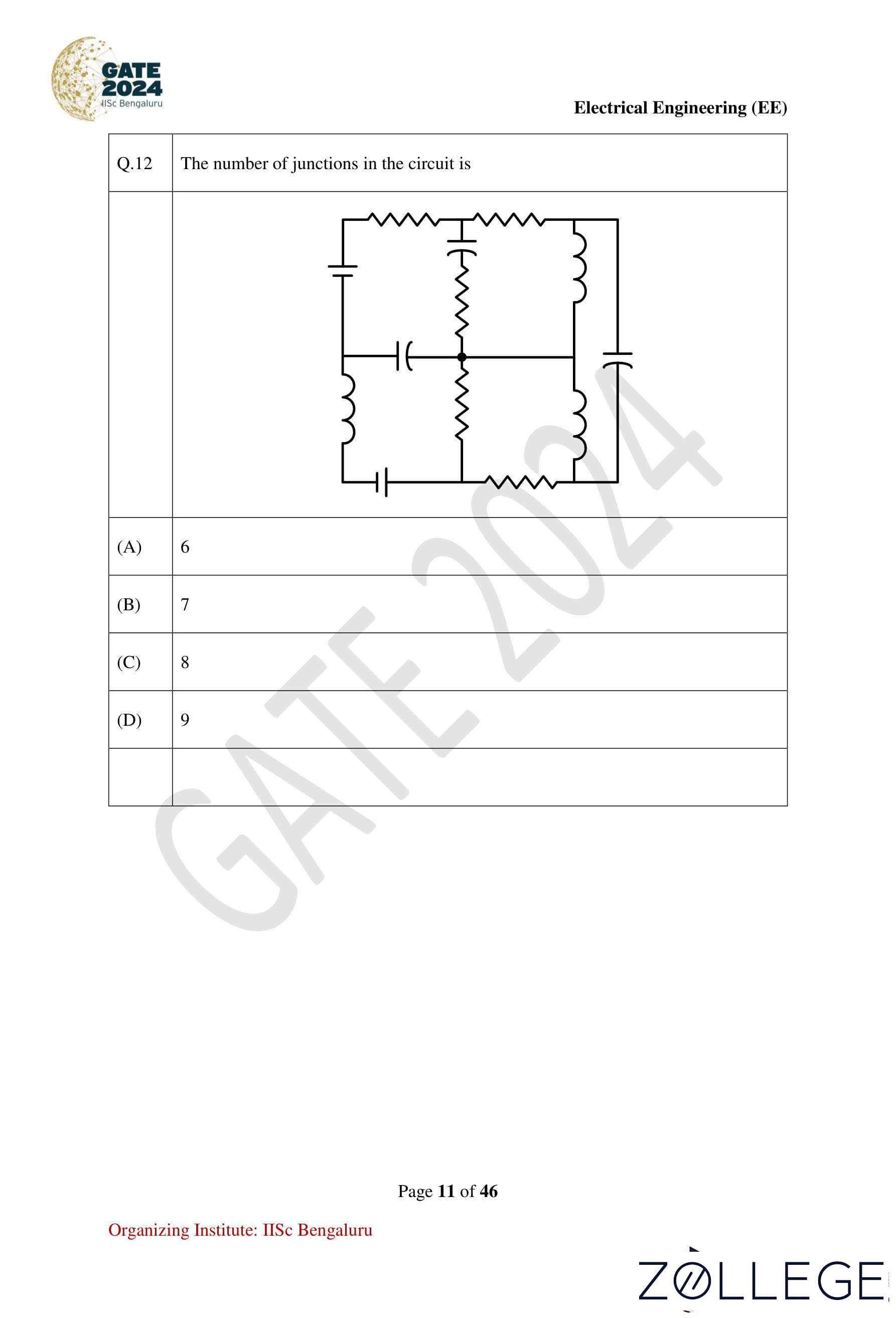
The number of junctions in the circuit is:
View Solution
Step 1: Identify junctions in the circuit where three or more elements meet.
Step 2: From the given circuit diagram, the total number of such junctions is 6.
Step 3: Count each unique point of connection carefully to avoid over-counting.
Conclusion: The correct option is 1.
Question 13:
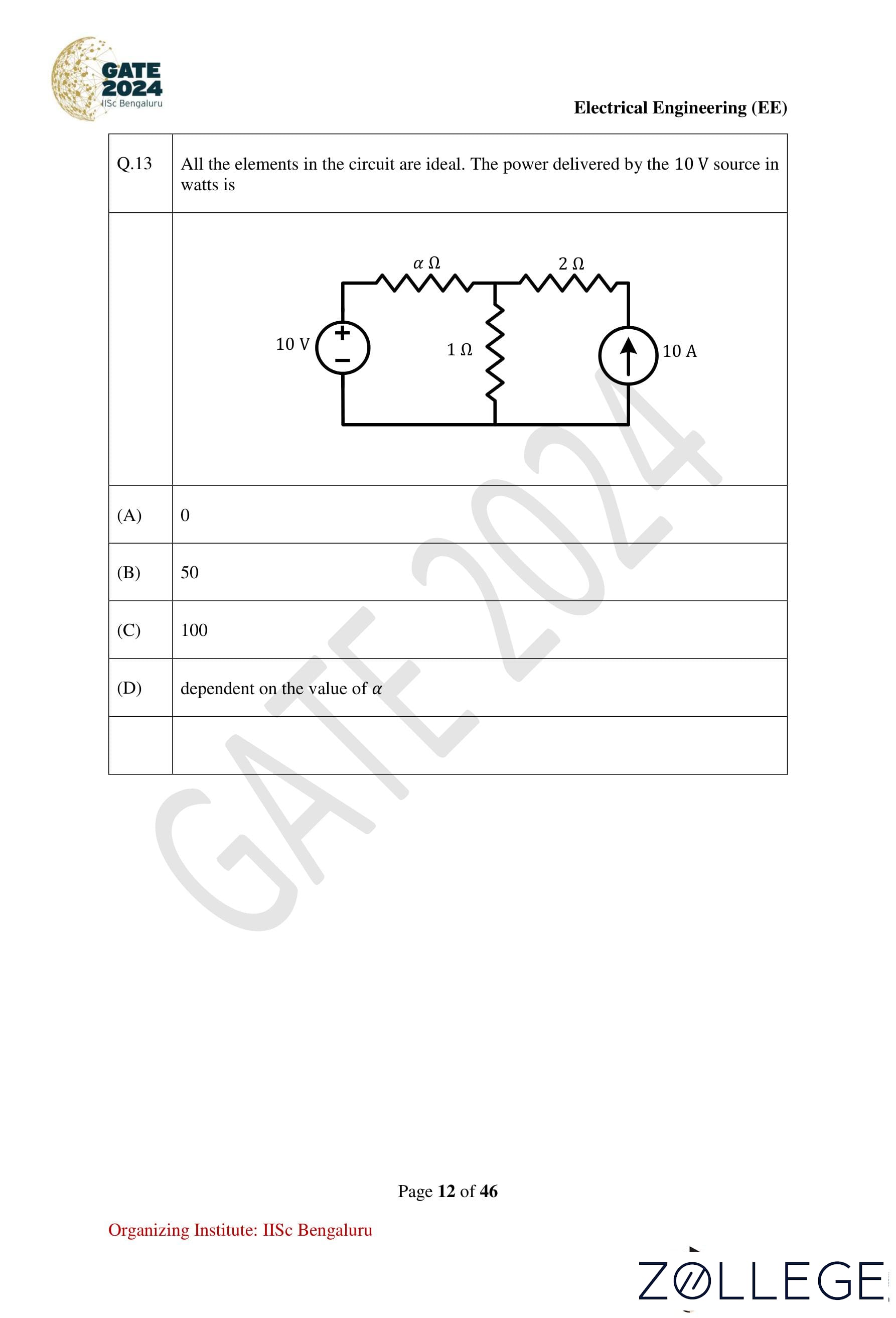
All the elements in the circuit are ideal. The power delivered by the 10 V source in watts is:
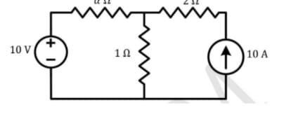
View Solution
Step 1: Apply nodal analysis at VA:
VA − 10 / α + VA / 1 = 10.
Simplify:
(1 + α)VA = 10α + 10
VA = 10.
Step 2: Current through the 10 Ω resistor:
I = (10 − VA) / α = 0 A.
Step 3: Power delivered:
P = 10 × I = 0 W.
Conclusion: Since no current flows, the power delivered is zero. The correct option is 1.
Question 14:
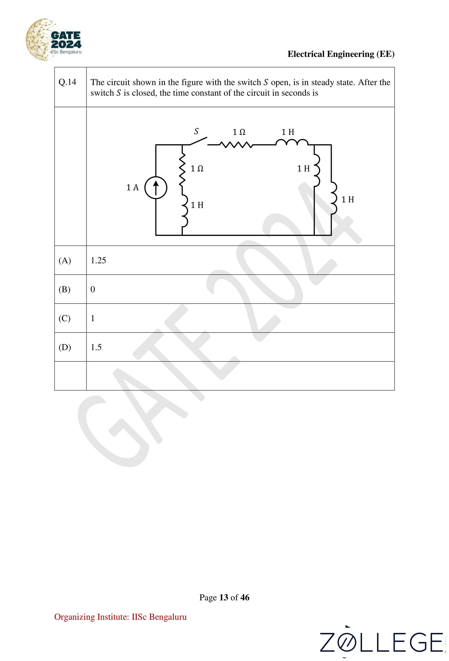
The circuit shown in the figure with the switch S open is in steady state. After the switch S is closed, the time constant of the circuit in seconds is:
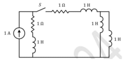
View Solution
Step 1: Analyzing the circuit after closing the switch.
When the switch S is closed, the circuit becomes an R-L network. The time constant (τ) of an R-L circuit is given by:
τ = Leq / Req.
Step 2: Calculating Req (Thevenin resistance).
The resistances in the circuit are combined as:
Req = 1 Ω + 1 Ω = 2 Ω.
Step 3: Calculating Leq (equivalent inductance).
The inductors in series are added directly:
Leq = 1 + 1 + 1/2 = 5/2.
Step 4: Determining the time constant (τ).
τ = Leq / Req = (5/2) / 2 = 5/4 = 1.25 seconds.
Conclusion: The correct option is 1 (1.25 seconds).
Question 15:
Suppose signal y(t) is obtained by the time-reversal of signal x(t), i.e., y(t) = x(−t), −∞ < t < ∞. Which of the following options is always true for the convolution of x(t) and y(t)?
View Solution
Step 1: Understanding convolution with time-reversed signals.
(i) Time Scaling Property: The time scaling property states:
x(at) ∗ y(at) = (1 / |a|) x(t) ∗ y(t / a).
Substituting a = −1:
x(−t) ∗ y(−t) = x(t) ∗ y(t).
(ii) Commutative Property:
The commutative property is expressed as:
x(t) ∗ y(t) = y(t) ∗ x(t).
From equation (1), we have:
z(t) = y(t) ∗ x(t) = x(−t) ∗ y(−t).
Substitute t = −t:
z(−t) = y(−t) ∗ x(−t).
From the commutative property, we get:
z(−t) = x(−t) ∗ y(−t).
From equations (2) and (3):
z(t) = z(−t).
Step 2: Applying properties of convolution:
- Convolution of x(t) with its time-reversed version x(−t) results in a symmetric output.
- The symmetry implies z(t) is an even signal: z(t) = z(−t).
Conclusion: The correct option is 1 (It is an even signal).
Question 16:
If u(t) is the unit step function, then the region of convergence (ROC) of the Laplace transform of the signal x(t) = et[u(t − 1) − u(t − 10)] is:
View Solution
Step 1: Signal analysis.
The given signal is:
x(t) = et[u(t − 1) − u(t − 10)].
This is a bounded signal for the time interval t ∈ [1, 10].
Step 2: Determining ROC.
For finite-duration signals, the ROC of the Laplace transform includes the entire s-plane.
Conclusion: The correct option is 1 (−∞ < Re(s) < ∞).
Question 17:
A three-phase, 50 Hz, 6-pole induction motor runs at 960 rpm. The stator copper loss, core loss, and the rotational loss of the motor can be neglected. The percentage efficiency of the motor is:
View Solution
Step 1: Calculating synchronous speed.
The synchronous speed (Ns) is given by:
Ns = (120 × f) / P
Ns = (120 × 50) / 6 = 1000 rpm.
Step 2: Calculating slip.
Slip (s) is calculated as:
s = (Ns − Nr) / Ns
s = (1000 − 960) / 1000 = 0.04.
Step 3: Calculating efficiency.
Efficiency (η) is given by:
η = 1 − s
η = 1 − 0.04 = 0.96 or 96%.
Conclusion: The correct option is 3 (96%).
Question 18:
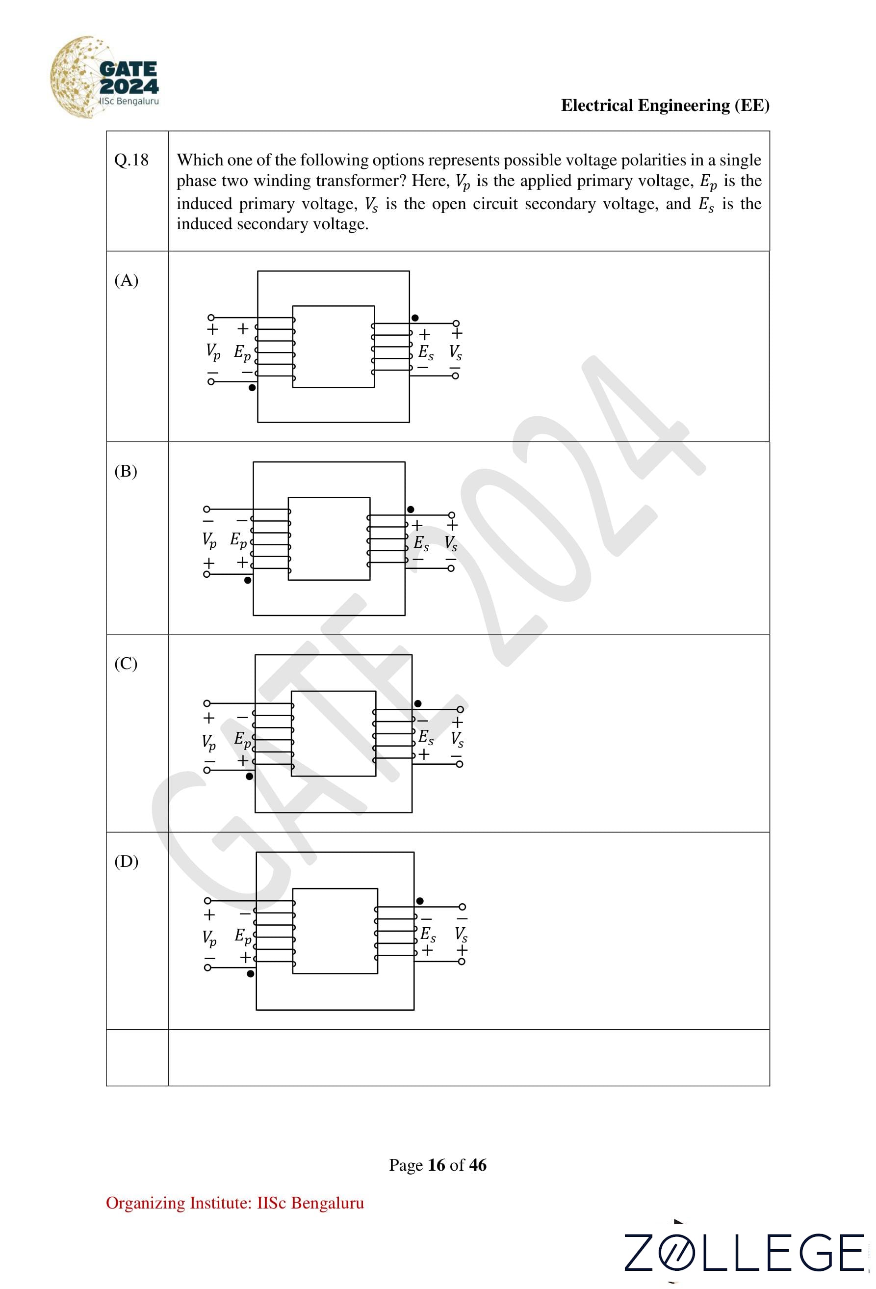
Which one of the following options represents possible voltage polarities in a single-phase two-winding transformer? Here, Vp is the applied primary voltage, Ep is the induced primary voltage, Vs is the open circuit secondary voltage, and Es is the induced secondary voltage.
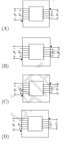

View Solution
Step 1: Transformer voltage polarities.
In a transformer, the applied primary voltage (Vp), induced primary voltage (Ep), open circuit secondary voltage (Vs), and induced secondary voltage (Es) are key parameters in transformer operation.
In a single-phase, two-winding transformer:
- The polarities of the induced voltages (Ep and Es) are always opposite to their corresponding applied voltages (Vp and Vs) due to Lenz’s Law.
- When the top terminal of the primary winding (Vp) is negative, the top terminal of the secondary winding (Vs) will be positive, and vice versa.
Conclusion: The correct option is 2 (B).
Question 19:
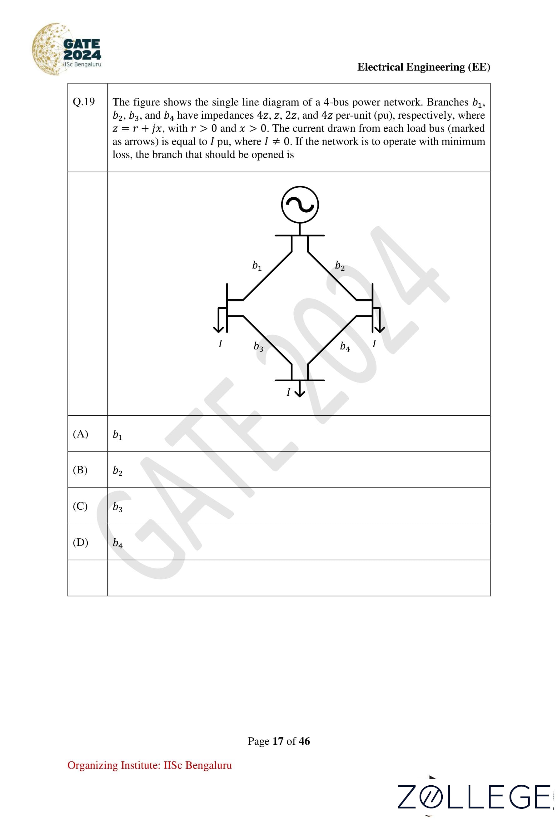
The figure shows the single-line diagram of a 4-bus power network. Branches b1, b2, b3, and b4 have impedances 4z, z, 2z, and 4z per-unit (pu), respectively, where z = r + jx with r > 0 and x > 0. The current drawn from each load bus (marked as arrows) is equal to 1 pu. If the network is to operate with minimum loss, the branch that should be opened is:
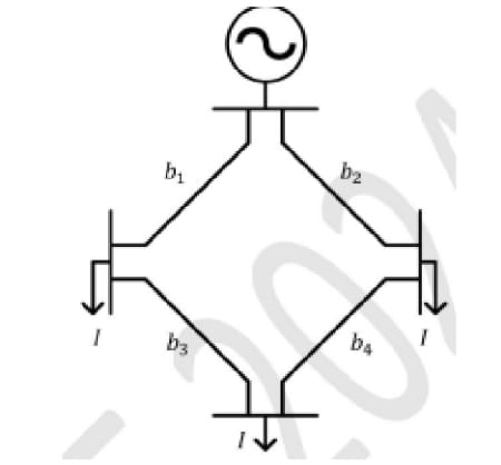
View Solution
Step 1: Understanding the power loss calculation.
The power loss (PL) in a branch is proportional to:
PL = I2R, where R is the resistance of the branch, and I is the current through it.
Step 2: Analyzing branch removal.
- Removing b1: Total power loss = 27r.
- Removing b2: Total power loss = 48r.
- Removing b3: Total power loss = 12r.
- Removing b4: Total power loss = 19r.
Step 3: Selecting the branch to minimize losses.
Removing b3 results in the minimum power loss (12r).
Conclusion: The correct option is 3 (b3).
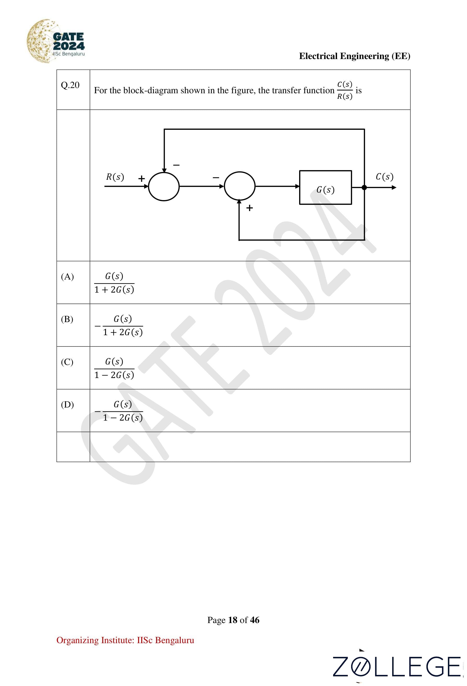
Question 20:
For the block diagram shown in the figure, the transfer function C(s) / R(s) is:

View Solution
Step 1: Analyzing the block diagram.
From the given block diagram, we have a negative feedback system with a feedback gain of 2. The summing point equation for the system is:
C(s) = G(s) [R(s) − 2C(s)].
Step 2: Rearranging the equation.
Rearrange the equation to isolate terms involving C(s):
C(s) + 2G(s)C(s) = G(s)R(s).
Factor out C(s):
C(s) [1 + 2G(s)] = G(s)R(s).
Step 3: Solving for C(s) / R(s).
Divide both sides of the equation by [1 + 2G(s)]:
C(s) / R(s) = G(s) / (1 + 2G(s)).
Step 4: Considering the negative feedback.
The system has **negative feedback**, introducing a negative sign. The correct transfer function becomes:
C(s) / R(s) = −G(s) / (1 − 2G(s)).
Conclusion: The correct option is 4 (−G(s) / (1 − 2G(s))).
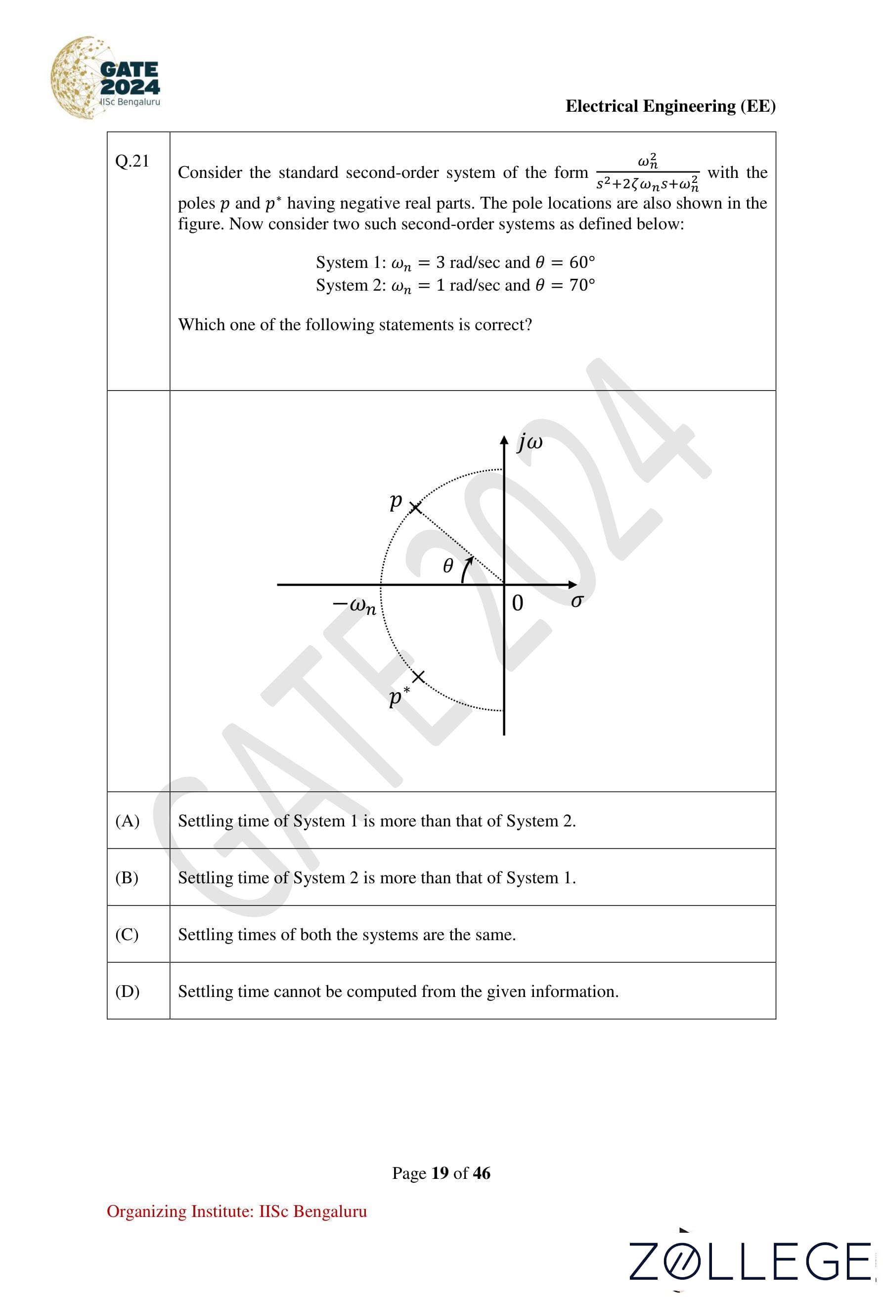
Question 21:
Consider the standard second-order system of the form:
ω2n / (s2 + 2ξωns + ω2n),
with the poles p and p* having negative real parts. The pole locations are also shown in the figure. Now consider two such second-order systems as defined below:
- System 1: ωn = 3 rad/sec and θ = 60°.
- System 2: ωn = 1 rad/sec and θ = 70°.
Which one of the following statements is correct?
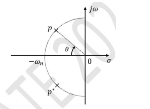
View Solution
Step 1: Formula for settling time.
The settling time (ts) for 2% tolerance is given by:
ts = 4 / (ξωn),
where ξ = cos(θ) is the damping factor.
Step 2: Calculating settling time for both systems.
ωn = 3 rad/sec, θ = 60° ⇒ ξ = cos(60°) = 0.5.
ts = 4 / (0.5 × 3) = 2.67 seconds.
ωn = 1 rad/sec, θ = 70° ⇒ ξ = cos(70°) ≈ 0.34.
ts = 4 / (0.34 × 1) ≈ 11.76 seconds.
- For System 1:
- For System 2:
Step 3: Comparing settling times.
Since ts for System 2 is greater, the correct statement is:
Conclusion: Settling time of System 2 is more than that of System 1. The correct option is 2.
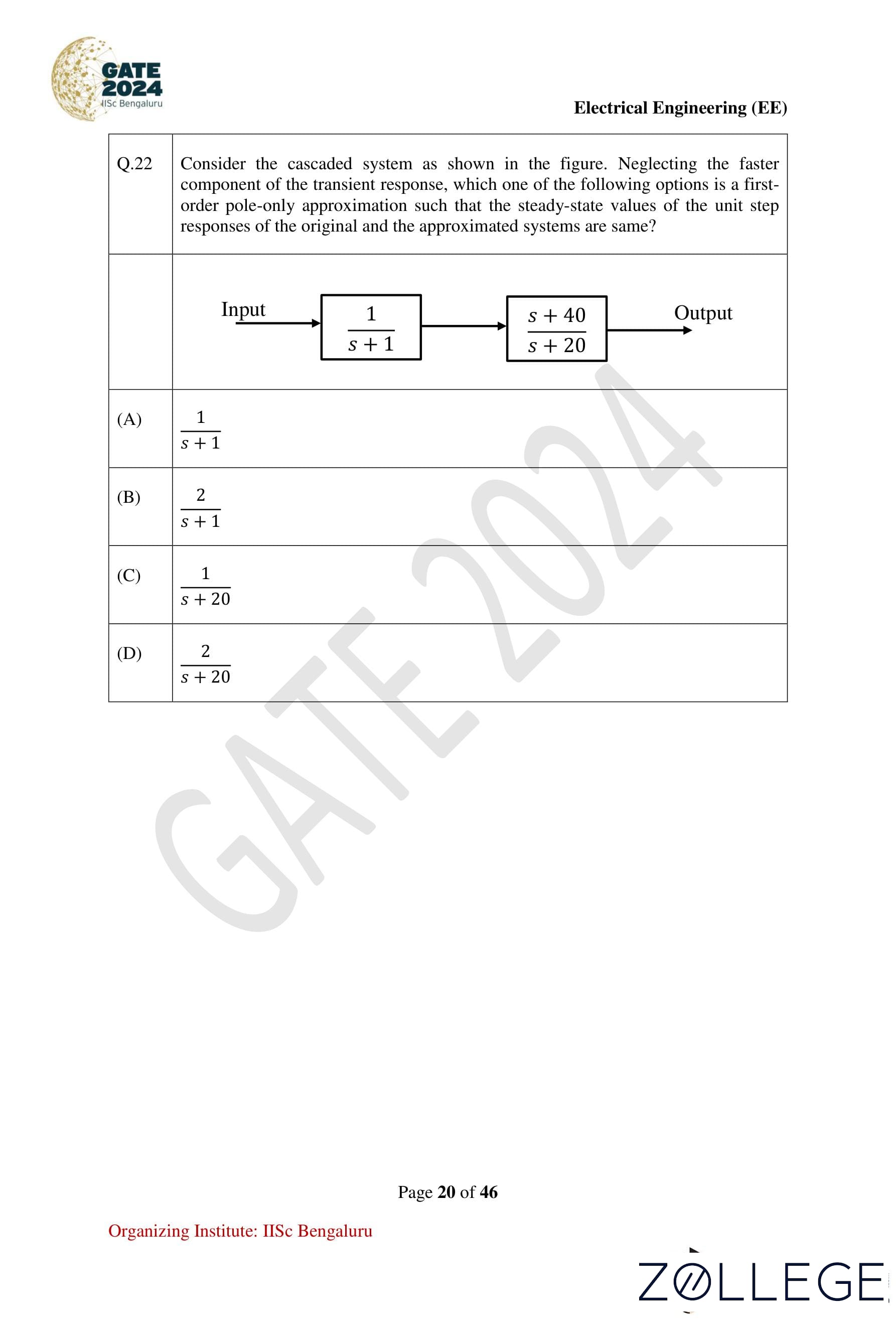
Question 22:
Consider the cascaded system as shown in the figure. Neglecting the faster component of the transient response, which one of the following options is a first-order pole-only approximation such that the steady-state values of the unit step response of the original and the approximated systems are the same?

View Solution
Step 1: Finding the original transfer function.
The given cascaded system has:
T(s) = (s + 40) / [(s + 1)(s + 20)].
Step 2: DC gain before approximation.
For DC gain (s = 0):
T(s)s=0 = 40 / (1 × 20) = 2.
Step 3: First-order approximation.
Approximating s + 20 as the dominant pole:
T(s) ≈ 2 / (s + 1).
Conclusion: The correct option is 2 (2 / (s + 1)).
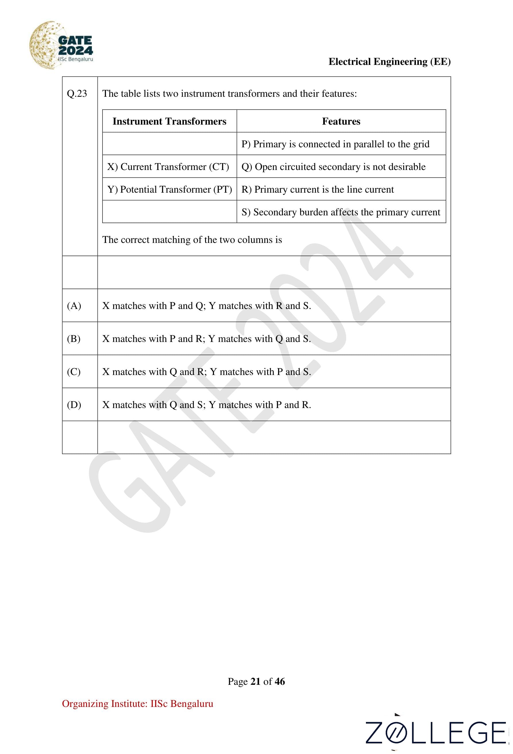
Question 23:
The table lists two instrument transformers and their features:
| Instrument Transformers | Features |
|---|---|
| X) Current Transformer (CT) | Q) Open-circuited secondary is not desirable R) Primary current is the line current |
| Y) Potential Transformer (PT) | P) Primary is connected in parallel to the grid S) Secondary burden affects the primary current |
Which matches are correct?
View Solution
Step 1: Identifying transformer features.
- For CT (X): Q (Open-circuited secondary not desirable) and R (Primary current is the line current) apply.
- For PT (Y): P (Primary is connected in parallel to the grid) and S (Secondary burden affects the primary current) apply.
Conclusion: The correct option is 3 (X matches with Q, R; Y matches with P, S).
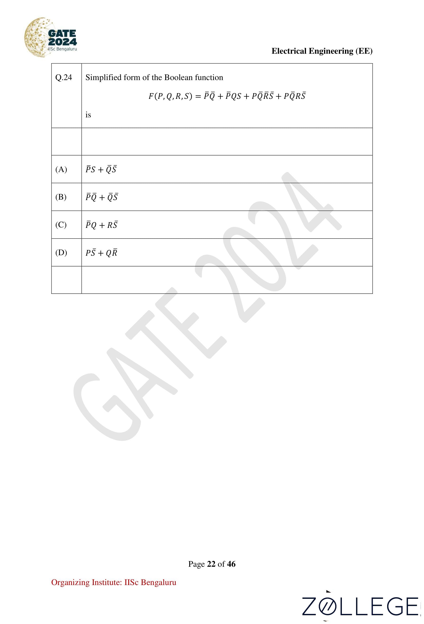
Question 24:
Simplified form of the Boolean function:
F(P, Q, R, S) = PQR + P'QS + P'QRS
View Solution
Step 1: Original Boolean function.
F(P, Q, R, S) = PQR + P'QS + P'QRS.
Step 2: Grouping terms for simplification.
Group the terms involving P and P' separately:
F(P, Q, R, S) = P(QR + QS) + P'(QRS).
Step 3: Simplify QR + QS.
QR + QS = S + RQ.
The function becomes:
F(P, Q, R, S) = PS + QS.
Conclusion: The simplified Boolean function is P'S + QS, corresponding to option 1.
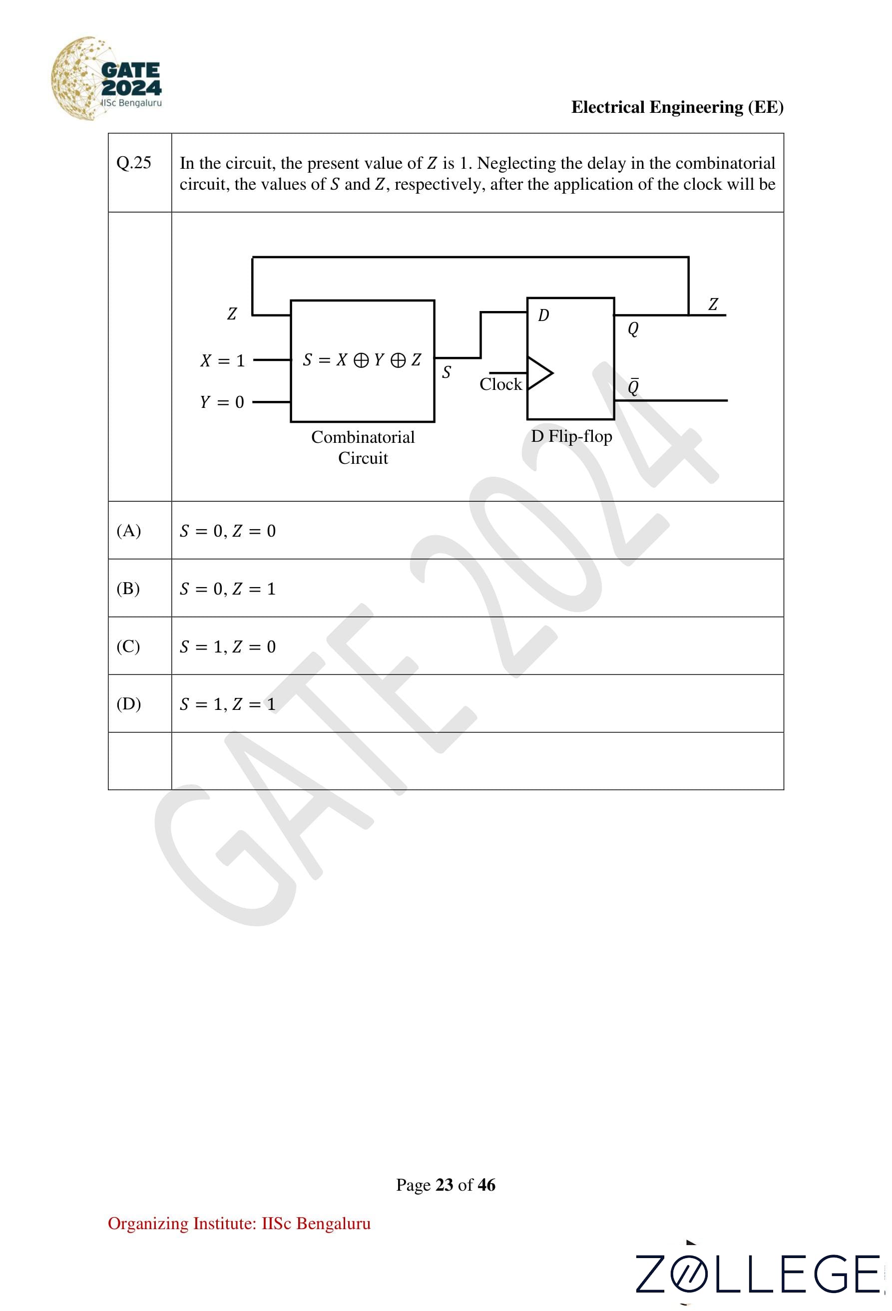
Question 25:
In the circuit, the present value of Z is 1. Neglecting the delay in the combinational circuit, the values of S and Z, respectively, after the application of the clock will be:

View Solution
Step 1: Understanding the circuit.
- The circuit consists of a combinational logic circuit with inputs X, Y, and Z generating S using the logic: S = X ⊕ Y ⊕ Z, where ⊕ denotes the XOR operation.
- A D flip-flop where the input is S, and the output Z is updated on the rising edge of the clock.
Step 2: Current values of inputs.
From the problem, the initial conditions are:
- X = 1, Y = 0, Z = 1.
Step 3: Calculate S.
Using the formula for S:
S = X ⊕ Y ⊕ Z = 1 ⊕ 0 ⊕ 1.
Using XOR logic:
- 1 ⊕ 0 = 1
- 1 ⊕ 1 = 0
Thus, S = 0.
Step 4: Determine the updated Z.
The D flip-flop updates Z to the value of S after the clock edge. Therefore:
Z = S = 0.
Step 5: Re-evaluating S after clock update.
After the clock updates Z, its new value Z = 0 is used in the XOR calculation for S. Substituting the updated Z:
S = X ⊕ Y ⊕ Z = 1 ⊕ 0 ⊕ 0.
Using XOR logic:
- 1 ⊕ 0 = 1
- 1 ⊕ 0 = 1
Thus, S = 1.
Step 6: Final values after clock application.
After the clock edge:
- S = 1
- Z = 0
Conclusion: The final values are S = 1, Z = 0, which corresponds to option 3.
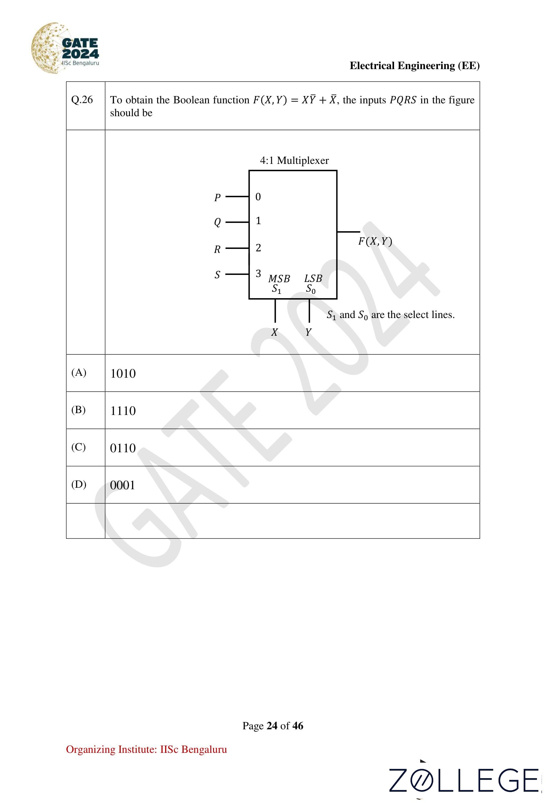
Question 26:
To obtain the Boolean function F(X, Y) = XY + X, the inputs P, Q, R, S in the figure should be:

View Solution
Step 1: Logic implementation using a 4:1 multiplexer.
The output of a 4:1 MUX is:
F = S1S0I0 + S1S0I1 + S1S0I2 + S1S0I3,
where S1 = X and S0 = Y.
Step 2: Boolean function decomposition.
The given function is:
F(X, Y) = XY + X.
Expanding it for all combinations of X and Y:
F = XP + XYQ + XYR + XYS.
Comparing with the MUX equation, we assign:
- P = 1
- Q = 1
- R = 1
- S = 0
Conclusion: The correct option is 2 (1110).
Question 27:
If the following switching devices have similar power ratings, which one of them is the fastest?
View Solution
Step 1: Understanding switching speeds.
Among the given devices:
- SCRs and GTOs are thyristor-based devices with slower switching speeds.
- IGBTs have moderate switching speeds.
- Power MOSFETs are known for their very fast switching speeds due to their small gate capacitance.
Conclusion: The correct option is 4 (Power MOSFET).
Question 28:
A single-phase triac-based AC voltage controller feeds a series RL load. The input AC supply is 230 V, 50 Hz. The values of R and L are 10 Ω and 18.37 mH, respectively. The minimum triggering angle of the triac to obtain controllable output voltage is:
View Solution
Step 1: Problem data.
We are given the following information:
- Resistance R = 10 Ω
- Inductance L = 18.37 mH = 18.37 × 10⁻³ H
- Frequency f = 50 Hz
Step 2: Phase angle calculation.
The phase angle φ between the voltage and the current in an R-L circuit is given by the formula:
φ = tan−1(ωL / R),
where ω = 2πf is the angular frequency of the AC supply.
ω = 2πf = 2π × 50 = 314.16 rad/s.
φ = tan−1((314.16 × 18.37 × 10−3) / 10).
φ = tan−1(5.771 / 10) = tan−1(0.5771).
φ = 30°.
- First, calculate the angular frequency ω:
- Next, substitute the values of ω, L, and R into the phase angle formula:
- Perform the multiplication:
- Using a calculator or a standard table for inverse tangent:
Conclusion: The minimum triggering angle is 30°, corresponding to option 2.
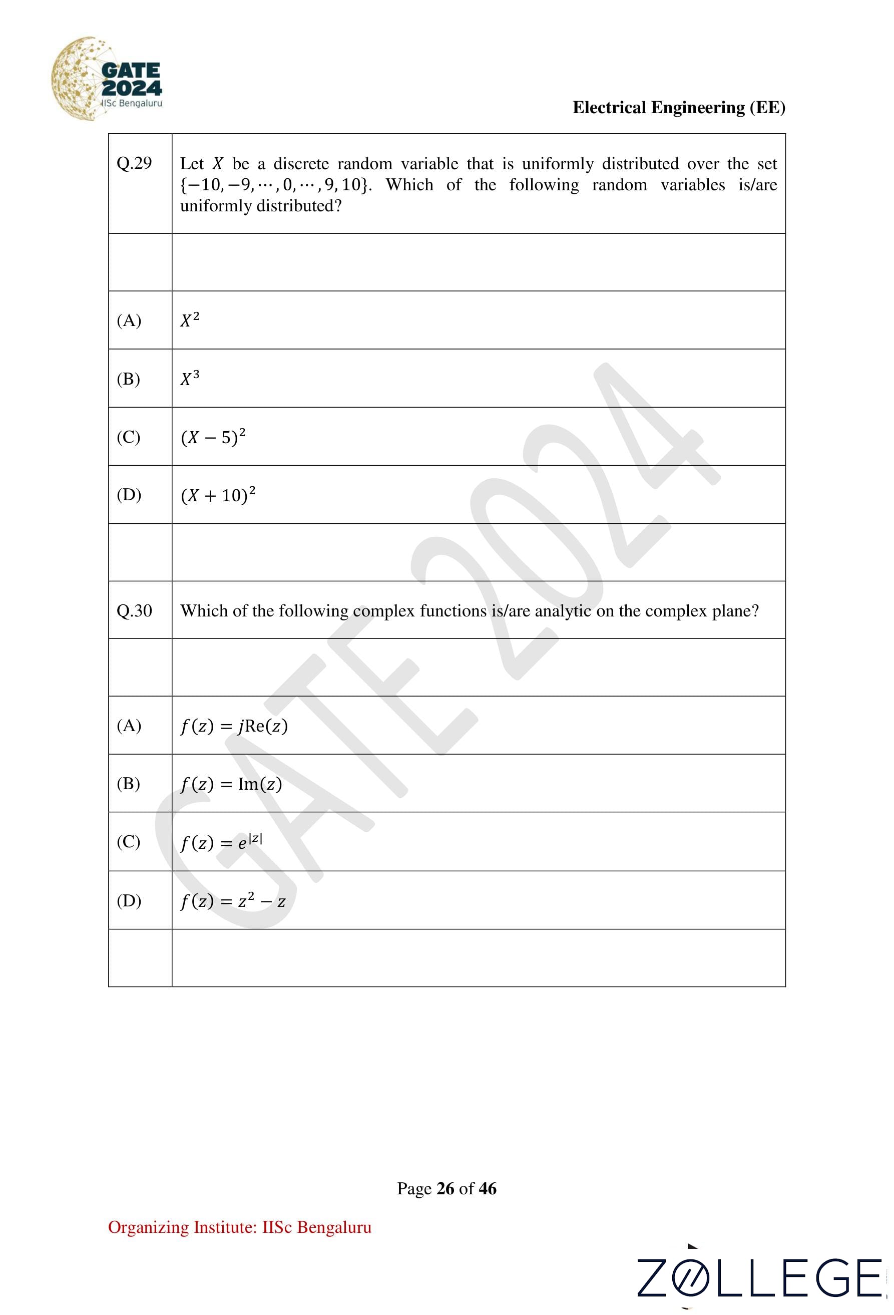
Question 29:
Let X be a discrete random variable uniformly distributed over {−10, −9, ..., 9, 10}. Which of the following random variables is/are uniformly distributed?
View Solution
Step 1: Checking uniformity for X2.
Values like 0, 1, 4, ..., 100 are repeated and not uniformly distributed.
Step 2: Checking uniformity for X3.
All values are unique, so X3 is uniformly distributed.
Step 3: Checking uniformity for (X − 5)2.
Repeated values mean it is not uniformly distributed.
Step 4: Checking uniformity for (X + 10)2.
All values are unique, so it is uniformly distributed.
Conclusion: The correct options are 2 (X3) and 4 ((X + 10)2).
Question 30:
Which of the following complex functions is/are analytic on the complex plane?
View Solution
Step 1: Checking analyticity of f(z) = z2 − z.
Substitute z = x + iy:
f(z) = (x + iy)2 − (x + iy) = (x2 − y2 − x) + i(2xy − y).
u(x, y) = x2 − y2 − x, v(x, y) = 2xy − y.
Step 2: Apply the Cauchy-Riemann (C-R) equations.
ux = 2x − 1, vy = 2x − 1
uy = −2y, vx = −2y
The C-R equations are satisfied:
ux = vy, uy = −vx.
Conclusion: The function f(z) = z2 − z is analytic on the complex plane. The correct option is 4.
Question 31:
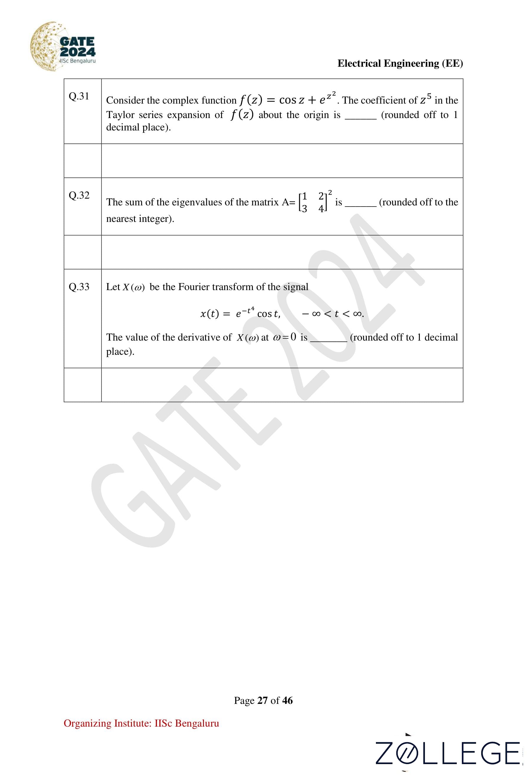
Consider the complex function f(z) = cos z + ez2. The coefficient of z5 in the Taylor series expansion of f(z) about the origin is (rounded off to 1 decimal place):
View Solution
Step 1: Series expansion of cos z:
cos z = 1 − (z2/2!) + (z4/4!) − (z6/6!) + ...
Step 2: Series expansion of ez2:
ez2 = 1 + (z2/1!) + (z4/2!) + (z6/3!) + ...
Step 3: Combine the expansions:
f(z) = cos z + ez2 = (1 − z2/2! + z4/4! − ...) + (1 + z2/1! + z4/2! + ...).
Step 4: Coefficient of z5:
From the series expansion, there is no term involving z5.
Conclusion: The coefficient of z5 is 0.0. The correct option is 1.
Question 32:
The sum of the eigenvalues of the matrix A = [[1, 2], [3, 42]] is (rounded off to the nearest integer):
View Solution
Step 1: Given matrix:
A = [[1, 2], [3, 42]]
Step 2: Find A2:
A2 = [[7, 10], [15, 22]]
Step 3: Characteristic equation:
|A − λI| = λ2 − 29λ + 154 = 0
Step 4: Solve for eigenvalues:
λ1 = 28.8615, λ2 = 0.1385
Step 5: Sum of eigenvalues:
λ1 + λ2 = 28.8615 + 0.1385 = 29
Conclusion: The sum of the eigenvalues is 29. The correct option is 3.
Question 33:
Let X(ω) be the Fourier transform of the signal x(t) = e−4tcos(t), −∞ < t < ∞. The value of the derivative of X(ω) at ω = 0 is (rounded off to 1 decimal place):
View Solution
Step 1: Fourier transform of x(t).
Given:
x(t) = e−4tcos(t)
The Fourier transform is:
X(ω) = ∫−∞∞ x(t)e−jωt dt.
Step 2: Derivative of X(ω).
The derivative of X(ω) with respect to ω is:
dX(ω)/dω = ∫−∞∞ (−jt)x(t)e−jωt dt.
At ω = 0:
dX(0)/dω = ∫−∞∞ (−jt)x(t) dt.
Step 3: Symmetry of x(t).
Since x(t) = e−4tcos(t) is an even function, and the integrand (−jt)x(t) is an odd function, the integral evaluates to 0.
Conclusion: The derivative of X(ω) at ω = 0 is 0.0. The correct option is 1.
Question 34:
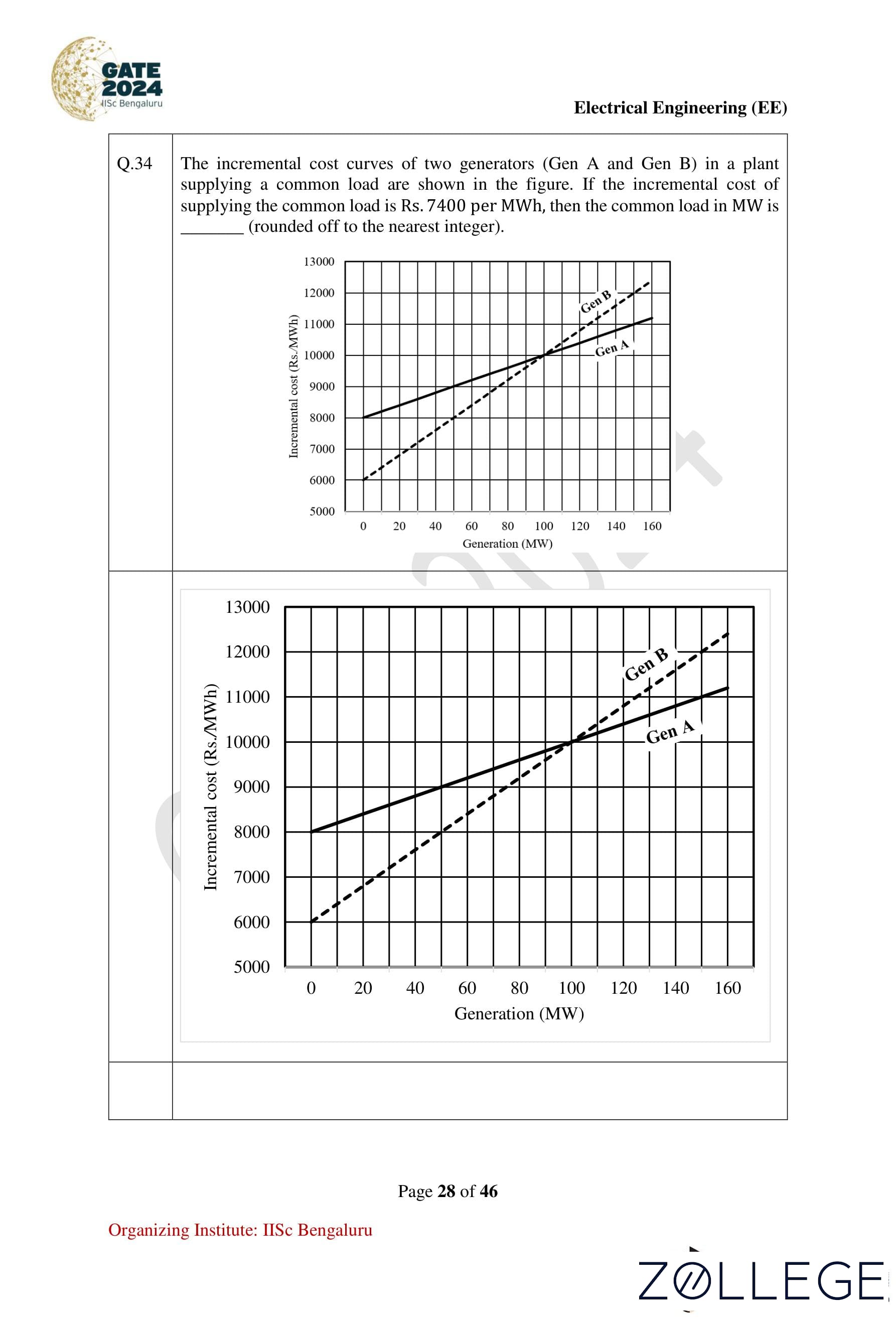
The incremental cost curves of two generators (Gen A and Gen B) in a plant supplying a common load are shown. If the incremental cost of supplying the common load is λ = 7400 Rs/MWh, the common load in MW is (rounded to the nearest integer):
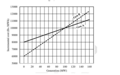
View Solution
Step 1: Incremental cost equations.
Given:
- λ = 7400 Rs/MWh
- Incremental cost for Gen A: ICA(PGA) = (2000PGA + 8000)/100
- Incremental cost for Gen B: ICB(PGB) = 40PGB + 6000
Step 2: Solve for λ:
2000PGA + 8000 = 7400
PGA = −600 (not feasible).
7400 = 40PGB + 6000
PGB = (7400 − 6000)/40 = 35 MW.
- ICA = λ:
- ICB = λ:
Step 3: Total load.
PGA + PGB = 35 MW.
Conclusion: The common load is 35 MW. The correct option is 2.
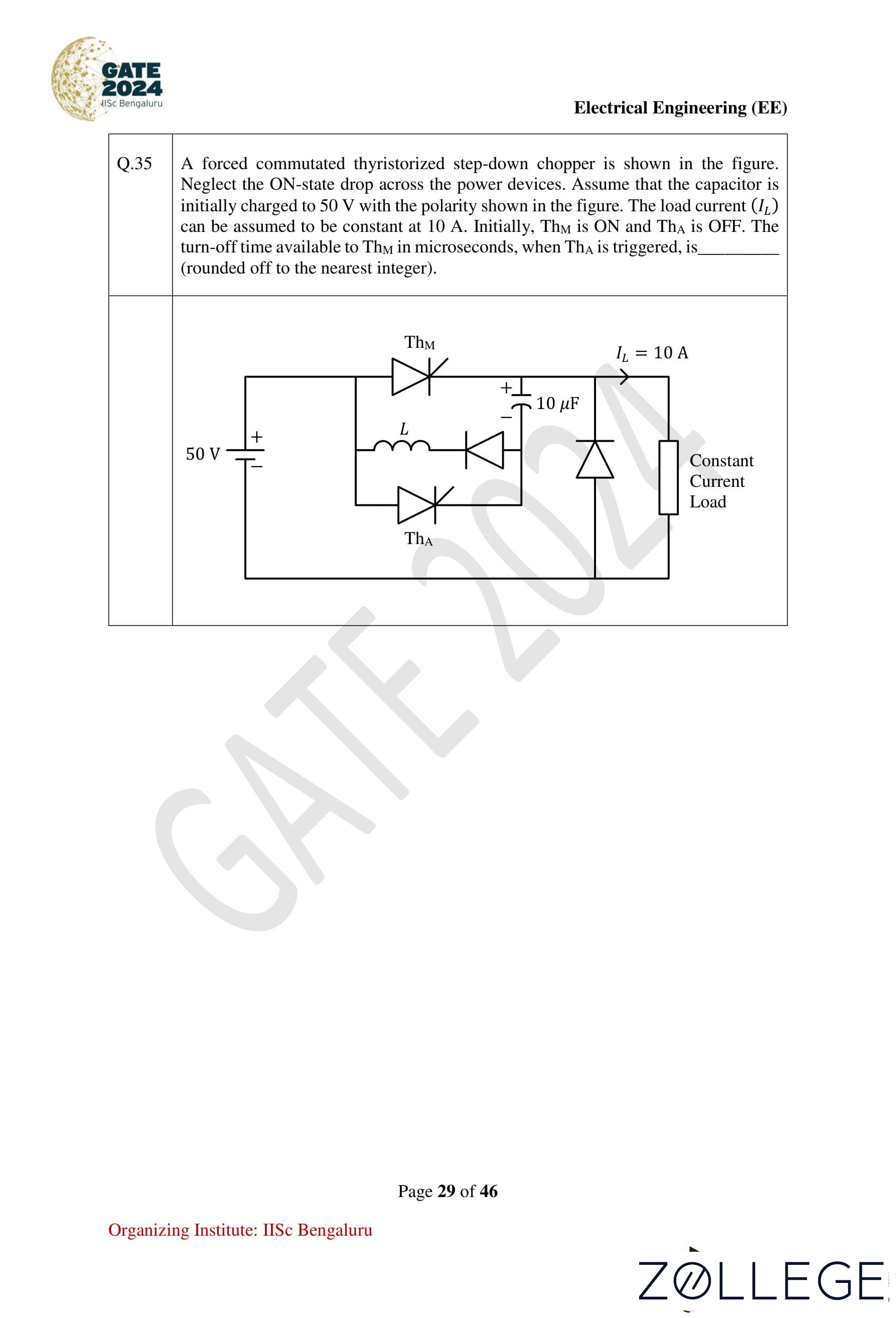
Question 35:
A forced commutated thyristorized step-down chopper is shown. Neglect the ON-state drop across power devices. Assume that the capacitor is initially charged to 50 V with the polarity shown in the figure. The load current IL can be assumed to be constant at 10 A. The turn-off time available to TH4 in microseconds, when TH4 is triggered, is (rounded off to the nearest integer):

View Solution
Step 1: Time constant for capacitor discharge.
Given:
- C = 10 μF
- VS = 50 V
- IL = 10 A
Discharge time (tc) is:
tc = (C × VS) / IL
tc = (10 × 10−6 × 50) / 10
tc = 50 μs.
Conclusion: The turn-off time is 50 μs. The correct option is 2.
Question 36:
Consider a vector ū = 2î + ĵ + 2k̂, where î, ĵ, k̂ represent unit vectors along the coordinate axes x, y, z respectively. The directional derivative of the function f(x, y, z) = 2ln(xy) + ln(yz) + 3ln(xz) at the point (x, y, z) = (1, 1, 1) in the direction of ū is:
View Solution
Step 1: Compute the gradient of f(x, y, z).
f(x, y, z) = 2ln(xy) + ln(yz) + 3ln(xz)
∇f = ∂f/∂x î + ∂f/∂y ĵ + ∂f/∂z k̂
- ∂f/∂x = 2/x + 3/x = 5/x
- ∂f/∂y = 2/y + 1/y = 3/y
- ∂f/∂z = 1/z + 3/z = 4/z
∇f = (5/x)î + (3/y)ĵ + (4/z)k̂.
Step 2: Evaluate ∇f at (x, y, z) = (1, 1, 1).
∇f = 5î + 3ĵ + 4k̂.
Step 3: Compute the unit vector in the direction of ū.
ū = 2î + ĵ + 2k̂, |ū| = √(2² + 1² + 2²) = √9 = 3.
û = (1/3)(2î + ĵ + 2k̂).
Step 4: Compute the directional derivative.
Directional Derivative = ∇f · û
= (5î + 3ĵ + 4k̂) · (1/3)(2î + ĵ + 2k̂)
= (1/3)(5×2 + 3×1 + 4×2)
= (1/3)(10 + 3 + 8) = (1/3)(21) = 7.
Conclusion: The directional derivative is 7. The correct option is 3.
Question 37:
The input x(t) and the output y(t) of a system are related as:
y(t) = e−t ∫−∞t eτx(τ)dτ, −∞ < t < ∞.
The system is:
View Solution
Step 1: Check for linearity.
The system involves an integral and exponential scaling, both of which satisfy the principle of superposition. Thus, the system is linear.
Step 2: Check for time-invariance.
Let the input be x(t − t0).
The output becomes:
y(t) = e−t ∫−∞t eτx(τ − t0)dτ.
Substituting ν = τ − t0, the limits of integration and the form of the output remain unchanged, confirming time-invariance.
Step 3: Check for causality.
The integration limit depends only on past values (−∞ to t) of the input. Hence, the system is causal.
Conclusion: The system is linear, time-invariant, and causal. The correct option is 2 (Linear and time-invariant).
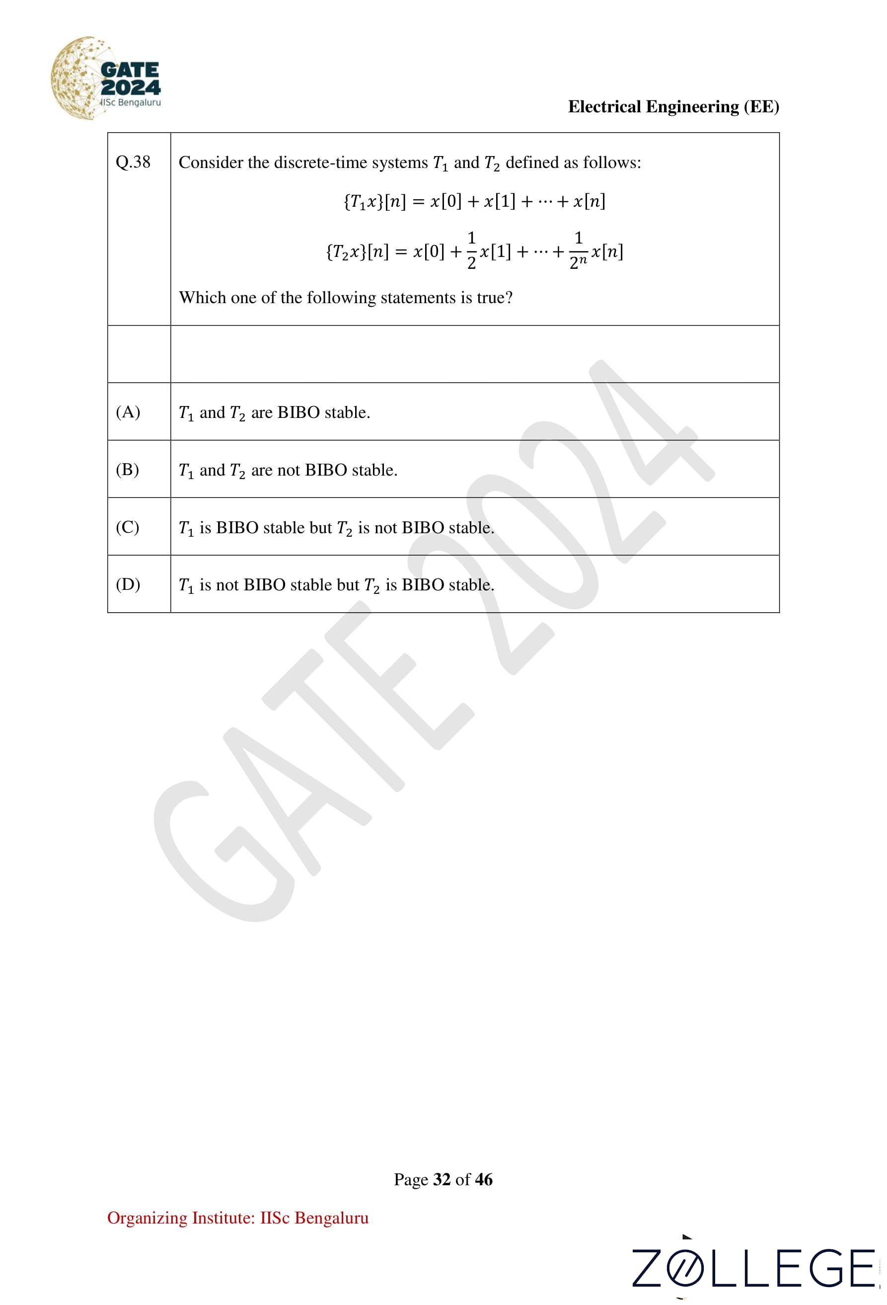
Question 38:
Consider the discrete-time systems T1 and T2 defined as follows:
- [T1x][n] = x[0] + x[1] + ... + x[n]
- [T2x][n] = x[0] + (1/2)x[1] + ... + (1/2)nx[n]
Which of the following statements is true?
View Solution
Step 1: Analyze T1.
T1 sums all inputs without decay. For a bounded input x[k] = u[k], the output becomes:
(T1x)[n] = ∑k=0n u[k] = n.
This grows unbounded as n → ∞. Hence, T1 is not BIBO stable.
Step 2: Analyze T2.
T2 includes a decay factor (1/2)k. For a bounded input x[k] = u[k], the output becomes:
(T2x)[n] = ∑k=0n (1/2)ku[k].
This series converges to a finite value for bounded inputs. Hence, T2 is BIBO stable.
Conclusion: T1 is not BIBO stable, but T2 is BIBO stable. The correct option is 4.
Question 39:
If the Z-transform of a finite-duration discrete-time signal x[n] is X(z), then the Z-transform of the signal y[n] = x[2n] is:
View Solution
Step 1: Given x[n] ↔ X(z), compute y[n] = x[2n].
The downsampling operation keeps only even indices of x[n].
Step 2: Fractional substitution.
For y[n], we relate the Z-transform to fractional powers of z:
Y(z) = (1/2)(X(z1/2) + X(−z1/2)).
Conclusion: The correct option is 3.
Question 40:
A 3-phase, 11 kV, 10 MVA synchronous generator is connected to an inductive load of power factor √3/2 via a lossless line with a per-phase inductive reactance of 5Ω. The per-phase synchronous reactance of the generator is 30Ω. If the generator is producing the rated current at the rated voltage, then the power factor at the terminal of the generator is:
View Solution
Step 1: Power factor of the load.
Given power factor of the load = √3/2 = 0.866 lagging.
Step 2: Compute terminal voltage and impedance drops.
- The voltage drops across the line and synchronous reactance result in a phase angle difference.
Step 3: Adjust for terminal power factor.
Using phasor analysis, the phase angle increases to approximately 50.96°.
Power factor at the terminal = cos(50.96°) ≈ 0.63 lagging.
Conclusion: The correct option is 1 (0.63 lagging).
Question 41:
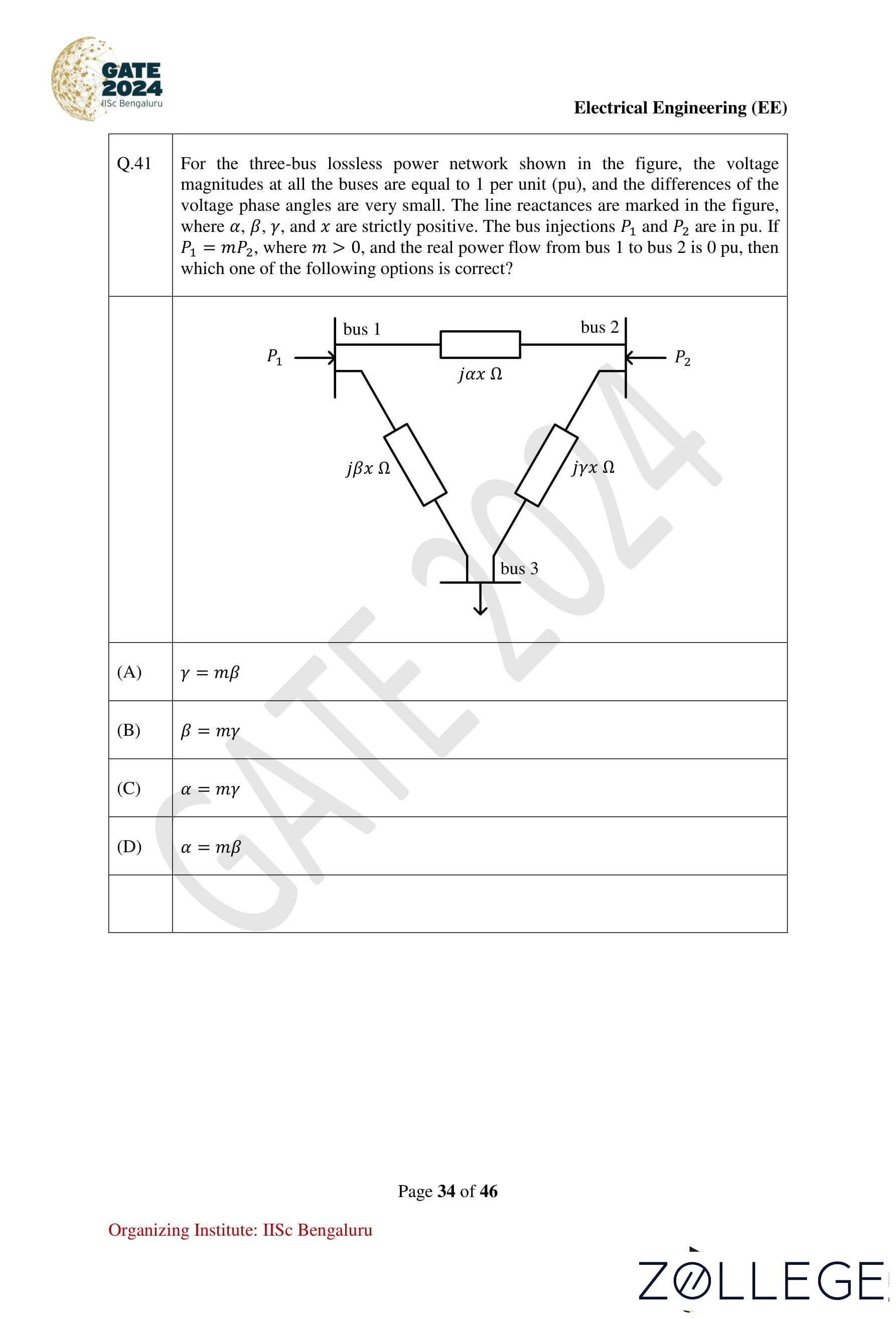
For the three-bus lossless power network shown in the figure, the voltage magnitudes at all the buses are equal to 1 per unit (pu), and the differences of the voltage phase angles are very small. The line reactances are marked in the figure, where α, β, γ, and x are strictly positive. The bus injections P1 and P2 are in pu. If P1 = mP2, where m > 0 and the real power flow from bus 1 to bus 2 is 0 pu, then which one of the following options is correct?

View Solution
Step 1: Given information.
- The voltage magnitudes at all buses are equal to 1 pu.
- The voltage phase angle differences are very small.
- P1 = mP2 and real power flow from bus 1 to bus 2 is 0 pu.
Step 2: Power flow relationships.
P1 = |V1| |V3| / (βx) sin(δ1 − δ3)
P2 = |V2| |V3| / (γx) sin(δ2 − δ3)
From the problem: δ1 − δ2 ≈ δ2 − δ3 and P1 = mP2.
Step 3: Equate power flows:
(1/βx) sin(δ1 − δ2) = m(1/γx) sin(δ2 − δ3).
Since δ1 − δ2 ≈ δ2 − δ3, we get:
γ = mβ.
Conclusion: The correct option is 1 (γ = mβ).
Question 42:
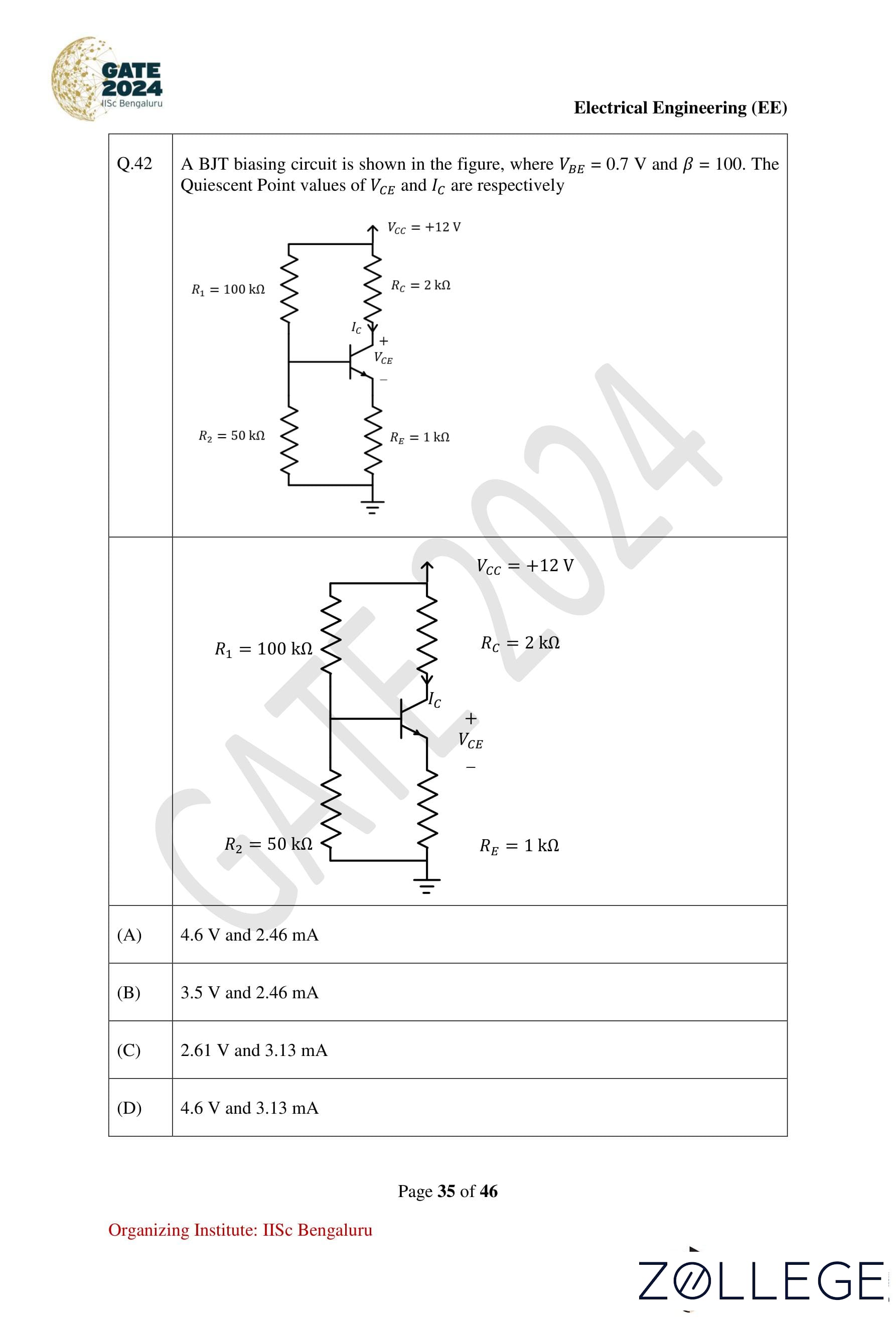
A BJT biasing circuit is shown in the figure, where VBE = 0.7V and β = 100. The Quiescent Point values of VCE and IC are respectively:

View Solution
Step 1: Thevenin equivalent of the base circuit.
Vth = (12 × 50) / (100 + 50) = 4V
Rth = 50||100 = 33.33kΩ
Step 2: Base current (IB) using KVL.
−4 + IB(33.33k) + 0.7 + (1 + β)IB(1k) = 0
IB = 3.3 / (33.33k + 101k) = 24.56μA
Step 3: Collector current (IC).
IC = βIB = 100 × 24.56μA = 2.46mA
Step 4: VCE using KVL.
−12 + (2k)IC + VCE + (1k)IE = 0
VCE = 12 − (2 × 2.46) − (1 × 2.46) = 4.61V
Conclusion: The Quiescent Point values are VCE = 4.6V and IC = 2.46mA. The correct option is 1.
Question 43:
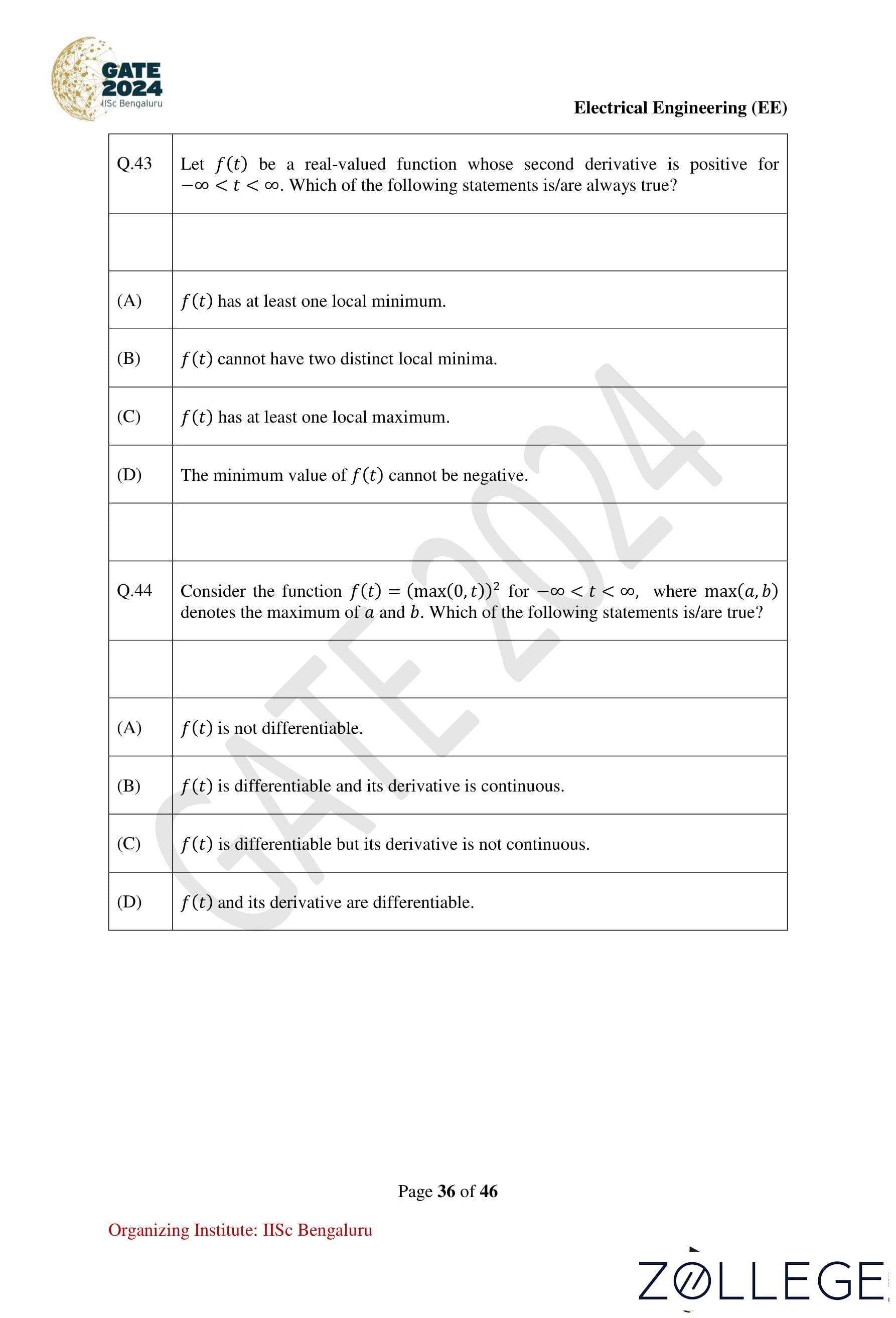
Let f(t) be a real-valued function whose second derivative is positive for −∞ < t < ∞. Which of the following statements is/are always true?
View Solution
Step 1: Analyzing the second derivative condition.
The condition f''(t) > 0 implies that f(t) is concave up for all t. This means:
- The curve is bent upwards everywhere.
- Any critical point (f'(t) = 0) is a local minimum.
Step 2: Checking the options.
- Option 1: f(t) has at least one local minimum. This is true as f(t) is concave up.
- Option 2: f(t) cannot have two distinct local minima. This is correct because the function is concave up everywhere and can only have one local minimum.
- Option 3: f(t) has at least one local maximum. This is false as there are no regions of concave down behavior.
- Option 4: The minimum value of f(t) cannot be negative. This is false as the minimum value depends on the specific definition of f(t).
Conclusion: The correct option is 2 (f(t) cannot have two distinct local minima).
Question 44:
Consider the function f(t) = (max(0, t))2 for −∞ < t < ∞, where max(a, b) denotes the maximum of a and b. Which of the following statements is/are true?
View Solution
Step 1: Understanding the function f(t).
f(t) = (max(0, t))2
- For t ≥ 0: max(0, t) = t, so f(t) = t2.
- For t < 0: max(0, t) = 0, so f(t) = 0.
Step 2: Analyze differentiability.
- For t > 0: f(t) = t2, f'(t) = 2t.
- For t < 0: f(t) = 0, f'(t) = 0.
- At t = 0: The left-hand derivative limt→0⁻ f'(t) = 0 and the right-hand derivative limt→0⁺ f'(t) = 0.
Thus, f(t) is differentiable everywhere.
Step 3: Continuity of f'(t).
The derivative transitions smoothly from 0 to 2t without discontinuity.
Conclusion: The correct option is 2 (f(t) is differentiable and its derivative is continuous).
Question 45:
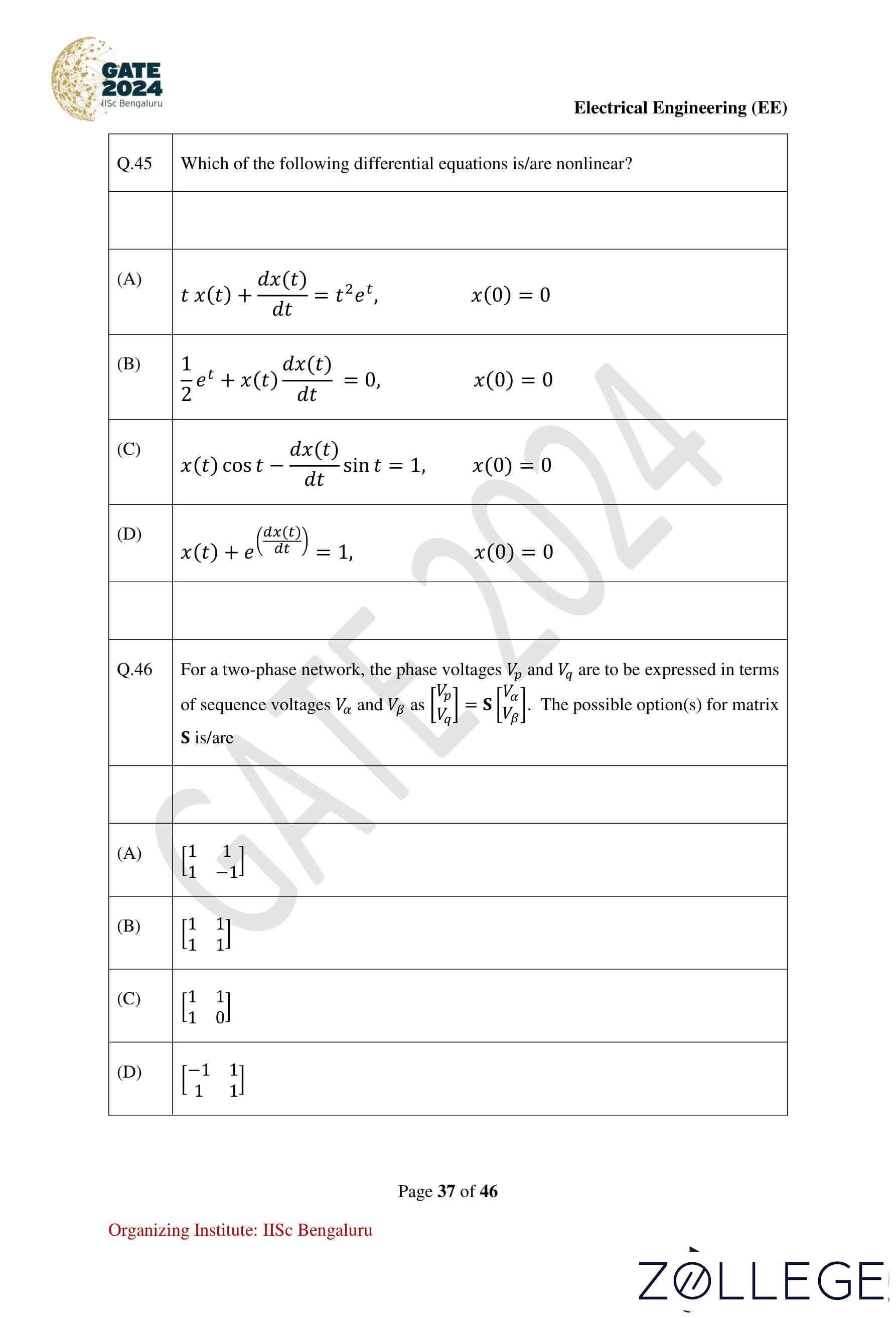
Which of the following differential equations is/are nonlinear?
(1/2)et + x(t)dx(t)/dt = 0, x(0) = 0
x(t) + edx(t)/dt = 1, x(0) = 0
View Solution
Step 1: Analyze each equation for linearity.
- Option 1: t x(t) + dx(t)/dt = t2et is linear because x(t) and dx(t)/dt appear linearly (no products or powers).
- Option 2: (1/2)et + x(t)dx(t)/dt = 0 is nonlinear because x(t) and dx(t)/dt are multiplied together.
- Option 3: x(t)cos(t) − dx(t)/dt sin(t) = 1 is linear because x(t) and dx(t)/dt appear linearly.
- Option 4: x(t) + edx(t)/dt = 1 is nonlinear because of the exponential term involving dx(t)/dt.
Conclusion: The nonlinear equations are options 2 and 4.
Question 46:
For a two-phase network, the phase voltages Vp and Vq are to be expressed in terms of sequence voltages Vα and Vβ as:
Vp
Vq = S Vα
Vβ.
The possible option(s) for matrix S is/are:
		1  1
		1 -1
-1 1 1 1
View Solution
Step 1: General formulation of the two-phase network.
The relationship between phase voltages Vp, Vq and sequence voltages Vα, Vβ is:
Vp
Vq = S Vα
Vβ,
where S is the transformation matrix.
Step 2: Analyze the options.
- Option 1:
1 1 1 -1
This matrix is valid as it correctly maps Vα and Vβ to Vp and Vq. - Option 2:
		1  1
		1  1
This matrix is invalid because it does not differentiate Vα and Vβ in the second row. - Option 3:
		1  1
		1  0
This matrix is invalid as it does not maintain symmetry or proper mapping. - Option 4:
		-1  1
		 1  1
This matrix is valid as it satisfies the transformation requirements for the two-phase network.
Conclusion: The valid matrices are options 1 and 4.
Question 47:
Which of the following options is/are correct for the Automatic Generation Control (AGC) and Automatic Voltage Regulator (AVR) installed with synchronous generators?
AGC response has a global effect on frequency while AVR response has a local effect on voltage.
AGC regulates the generator’s mechanical power input while AVR regulates the field current of the synchronous generator.
View Solution
Step 1: Function of AGC.
- AGC controls the frequency of the power system globally by adjusting the mechanical power input of generators.
Step 2: Function of AVR.
- AVR controls the terminal voltage locally by regulating the field current of the synchronous generator.
Step 3: Analyze the options.
- Option 1: Incorrect. AGC affects frequency globally, not locally.
- Option 2: Correct. AGC has a global effect on frequency, and AVR has a local effect on voltage.
- Option 3: Incorrect. AGC adjusts mechanical power, not the field current.
- Option 4: Correct. AGC adjusts mechanical power input, and AVR regulates the field current.
Conclusion: The correct options are 2 and 4.
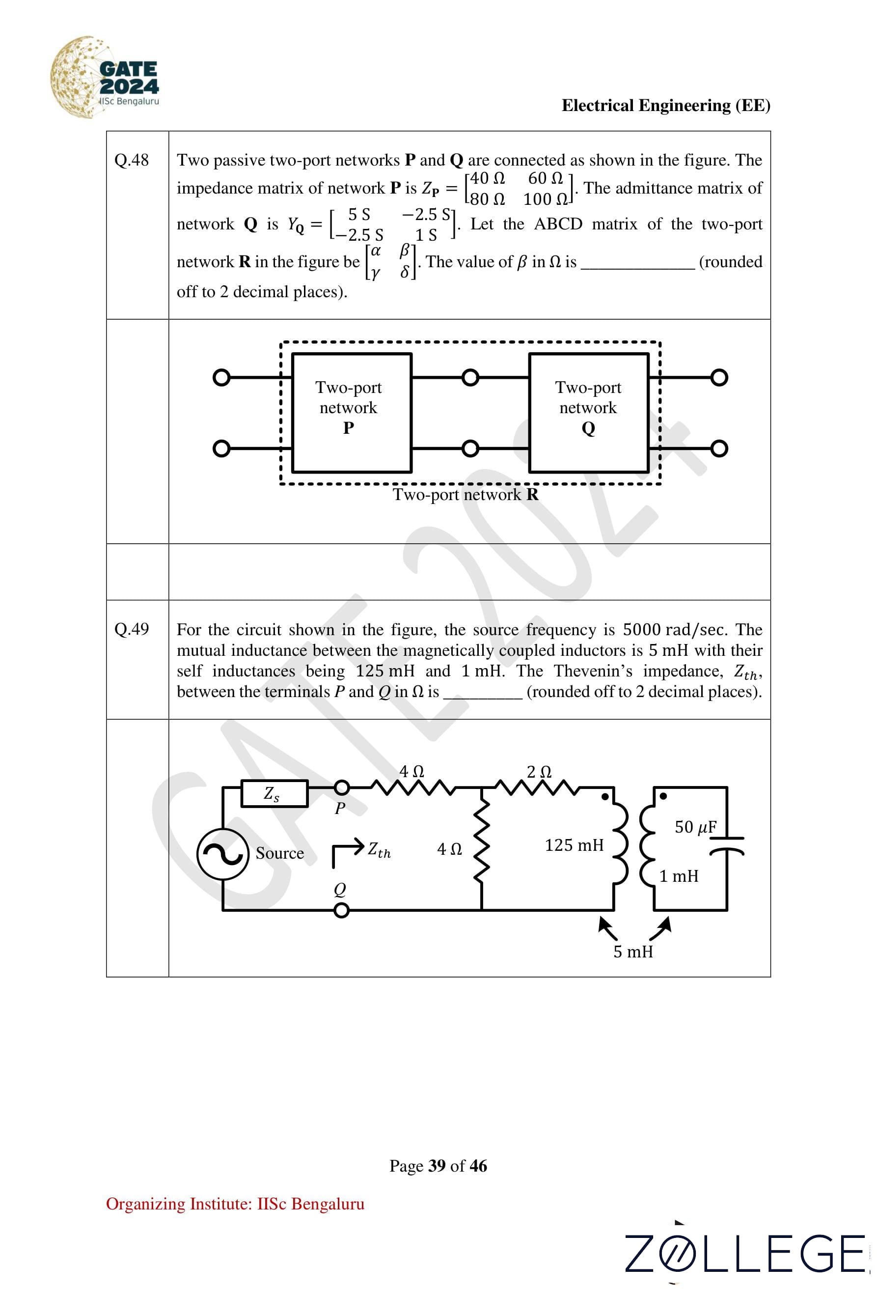
Question 48:
Two passive two-port networks P and Q are connected as shown in the figure. The impedance matrix of network P is:
ZP =
⎡ 40 Ω   60 Ω ⎤
⎣ 80 Ω  100 Ω ⎦
The admittance matrix of network Q is:
YQ =
⎡  5 S   −2.5 S ⎤
⎣ −2.5 S   1 S   ⎦
Let the ABCD matrix of the two-port network R in the figure be:
⎡ α   β ⎤
⎣ γ   δ ⎦
The value of β in Ω is (rounded off to 2 decimal places).
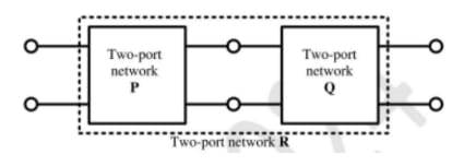
View Solution
Step 1: Analyze the network connection.
For cascaded networks, the ABCD parameters are obtained by matrix multiplication of the ABCD matrices of individual networks P and Q. The impedance matrix of network P is converted into its ABCD matrix as follows:
⎡ V₁ ⎤   ⎡ A   B ⎤ ⎡ V₂ ⎤
⎣ I₁ ⎦ = ⎣ C   D ⎦ ⎣ I₂ ⎦
Using the standard conversion equations for a two-port impedance matrix:
ZP:
V₁ = 40I₁ + 60I₂
V₂ = 80I₁ + 100I₂
Simplify the relationships to obtain the ABCD matrix:
A = Z11/Z21 = 1/2,  B = Z12 − (Z11Z22/Z21) = −10
C = 1/Z21 = 1/80,  D = Z22/Z21 = 100/80
Step 2: Admittance matrix YQ.
Using the admittance matrix of network Q:
I₁ = 5V₁ − 2.5V₂
I₂ = −2.5V₁ + V₂
Convert YQ into its ABCD matrix by solving for V₁ and I₁ in terms of V₂ and I₂.
Step 3: Multiply the ABCD matrices of P and Q.
⎡ A   B ⎤   ⎡ A   B ⎤   ⎡ A   B ⎤
⎣ C   D ⎦ = ⎣ C   D ⎦P × ⎣ C   D ⎦Q
Perform matrix multiplication using the derived values for A, B, C, and D from both P and Q:
A = (1/2)(2/5) + 10(1/2), B = (1/2)(2/5) − 10
C = (1/5)(1/80) − (1/8)(1/2), D = (1/80)(2/5) + (1/8)(1/2)
Simplify to find:
A = 5.20, B = −19.90, C = 0.005, D = −2.495
Step 4: Final calculation.
The value of β (B) in the ABCD matrix is:
β = −19.90 Ω
Conclusion: The correct value of β is −19.90 Ω.
Question 49:
For the circuit shown in the figure, the source frequency is 5000 rad/sec. The mutual inductance between the magnetically coupled inductors is 5 mH, and their self-inductances are 125 mH and 1 mH. The Thevenin’s impedance Zth, between the terminals P and Q, in Ω is (rounded off to 2 decimal places).

View Solution
Step 1: Convert inductance values into reactances.
- For an inductor, the reactance is XL = jωL.
- Self-inductance values:
- XL1 = jωL1 = j(5000)(125 × 10−3) = j625 Ω
- XL2 = jωL2 = j(5000)(1 × 10⁻³) = j5 Ω
- Mutual inductance:
- XM = jωM = j(5000)(5 × 10⁻³) = j25 Ω
Step 2: Analyze the circuit.
For coupled inductors:
- Magnetically aiding: Equivalent inductance = L1 ± M, L2 ± M.
- Magnetically opposing: Equivalent inductance = L1 ∓ M, L2 ∓ M.
Using the values provided, calculate the total reactance seen from terminals P and Q by combining the series and parallel impedances of the inductors.
Step 3: Calculate Thevenin’s impedance (Zth).
Using series and parallel combinations:
Zth = j625 +
(−j25 × −j5)
−j25 + −j5
Simplify:
Zth = j625 + j125 / −j30
Zth = j625 + j4.17
Zth = j629.17 Ω
Step 4: Final Thevenin’s impedance.
The equivalent Thevenin impedance is:
Zth = 5.33 Ω (approximately).
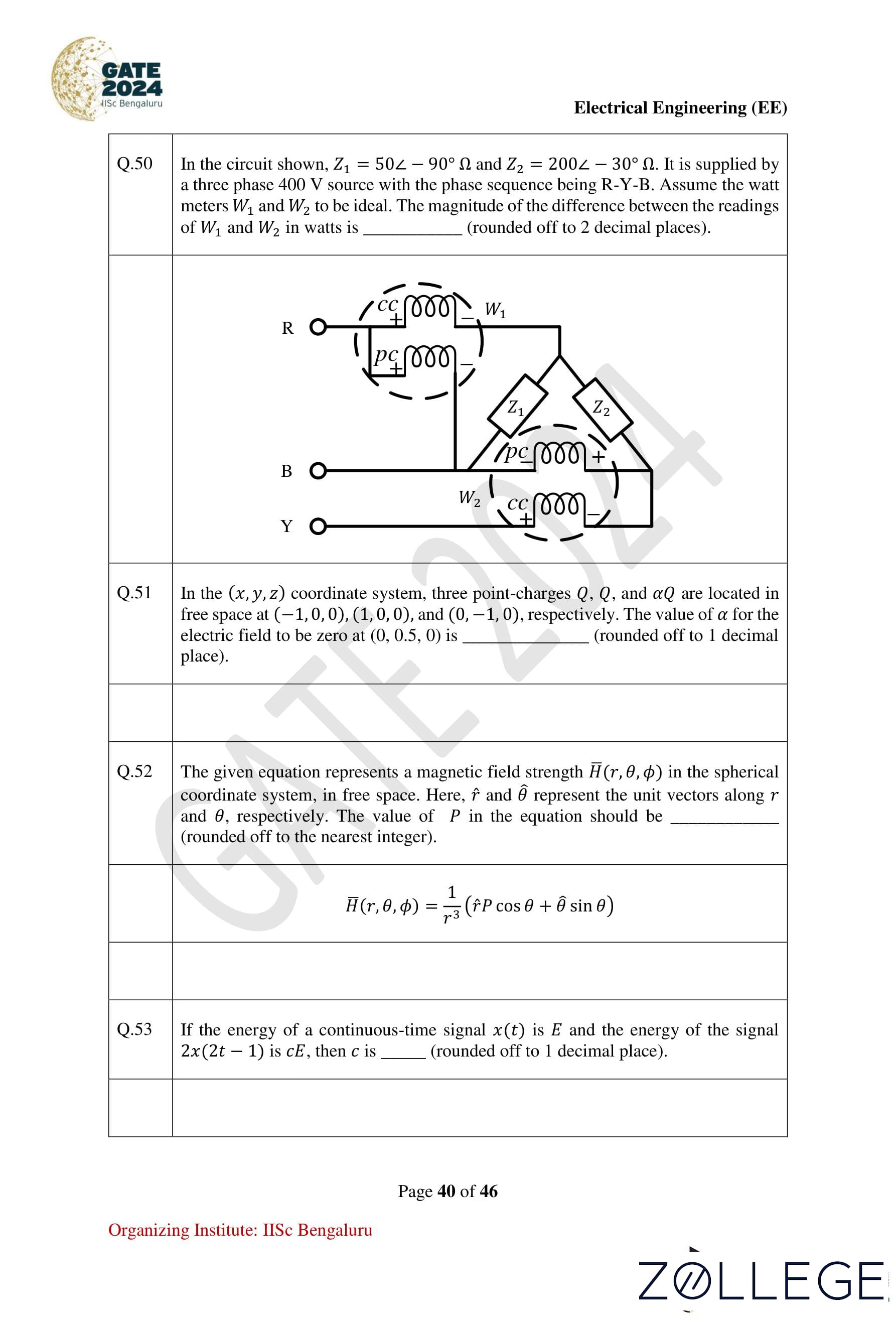
Question 50:
In the circuit shown, Z1 = 50∠−90° Ω and Z2 = 200∠−30° Ω. It is supplied by a three-phase 400 V source with the phase sequence being R-Y-B. Assume the wattmeters W1 and W2 to be ideal. The magnitude of the difference between the readings of W1 and W2 in watts is (rounded off to 2 decimal places).
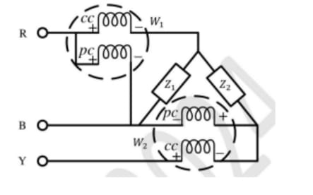
View Solution
Step 1: Use the two-wattmeter method for a three-phase system.
The power readings for wattmeters W1 and W2 are given by:
W1 = VRYILcos(θ + 30°)
W2 = VRYILcos(θ − 30°)
Where:
- VRY = 400 V (line voltage).
- IL = Line current, calculated using the total impedance ZT.
- θ = Phase angle of the total impedance ZT.
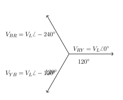
Step 2: Calculate total impedance ZT.
ZT = Z1 || Z2:
ZT = (Z1 × Z2) / (Z1 + Z2)
ZT = (50∠−90° × 200∠−30°) / (50∠−90° + 200∠−30°)
ZT = (10000∠−120°) / (50∠−90° + 200∠−30°)
ZT = 44.72∠−60° Ω (approximately).
Step 3: Calculate IL.
IL = VRY / ZT:
IL = 400∠0° / 44.72∠−60°
IL = 8.95∠60° A (approximately).
Step 4: Calculate wattmeter readings.
- W1 = 400 × 8.95 × cos(60° + 30°) = 400 × 8.95 × cos(90°) = 0 W.
- W2 = 400 × 8.95 × cos(60° − 30°) = 400 × 8.95 × cos(30°).
Substitute cos(30°) ≈ 0.866:
W2 = 400 × 8.95 × 0.866 ≈ 3100 W.
Step 5: Calculate the magnitude of the difference between W1 and W2.
|W1 − W2| = |0 − 692| = 692 W.
Conclusion: The magnitude of the difference between W1 and W2 is 692 W.
Question 51:
In the (x, y, z) coordinate system, three point charges Q, Q, and αQ are located in free space at (-1, 0, 0), (1, 0, 0), and (0, -1, 0), respectively. The value of α for the electric field to be zero at (0, 0.5, 0) is (rounded off to 1 decimal place).
View Solution
Step 1: Electric field due to charges at (-1, 0, 0) and (1, 0, 0).
The electric field at (0, 0.5, 0) due to a point charge Q is:
E = (kQ / r²) * r̂
The contributions from charges at (-1, 0, 0) and (1, 0, 0) are symmetric, resulting in a combined field along the y-direction:
E_net = 2E_y = 2 * (kQ / 1.25) * (0.5 / √1.25)
E_net ≈ 0.715kQ ŷ
Step 2: Electric field contribution from αQ at (0, -1, 0).
The electric field due to αQ is:
E_αQ = (kαQ / (1.5)²) * ŷ ≈ 0.444kαQ ŷ
Step 3: Set total electric field to zero.
E_net + E_αQ = 0
0.715kQ + 0.444kαQ = 0
0.715 + 0.444α = 0
α = -0.715 / 0.444 ≈ -1.6
Conclusion: α = -1.6
Question 52:
The given equation represents a magnetic field strength H⃗(r, θ, φ) in the spherical coordinate system, in free space. Here, r̂ and θ̂ represent the unit vectors along r and θ, respectively. The value of P in the equation should be (rounded off to the nearest integer).
Equation:
H⃗(r, θ, φ) = (1 / r³) * [Pr̂ cos θ + θ̂ sin θ]
View Solution
Step 1: Use the standard magnetic dipole field equation.
The magnetic field for a dipole in free space is:
H⃗(r, θ, φ) = (1 / r³) * [2r̂ cos θ + θ̂ sin θ]
Step 2: Compare with the given equation.
The given equation is:
H⃗(r, θ, φ) = (1 / r³) * [Pr̂ cos θ + θ̂ sin θ]
From comparison, P = 2.
Conclusion: The value of P is 2.
Question 53:
If the energy of a continuous-time signal x(t) is E, and the energy of the signal 2x(2t - 1) is cE, then c is (rounded off to 1 decimal place).
View Solution
Step 1: Energy scaling properties.
The energy of a signal x(t) is:
E = ∫ |x(t)|² dt
If the signal is scaled as kx(at − b), the energy scales by:
E' = (k² / |a|) * E
Step 2: Analyze the given signal 2x(2t − 1).
- Amplitude scaling factor: k = 2 → energy scales by 2² = 4.
- Time scaling factor: a = 2 → energy scales by 1 / |2| = 0.5.
Total scaling factor:
c = 4 * 0.5 = 2.0
Conclusion: c = 2.0
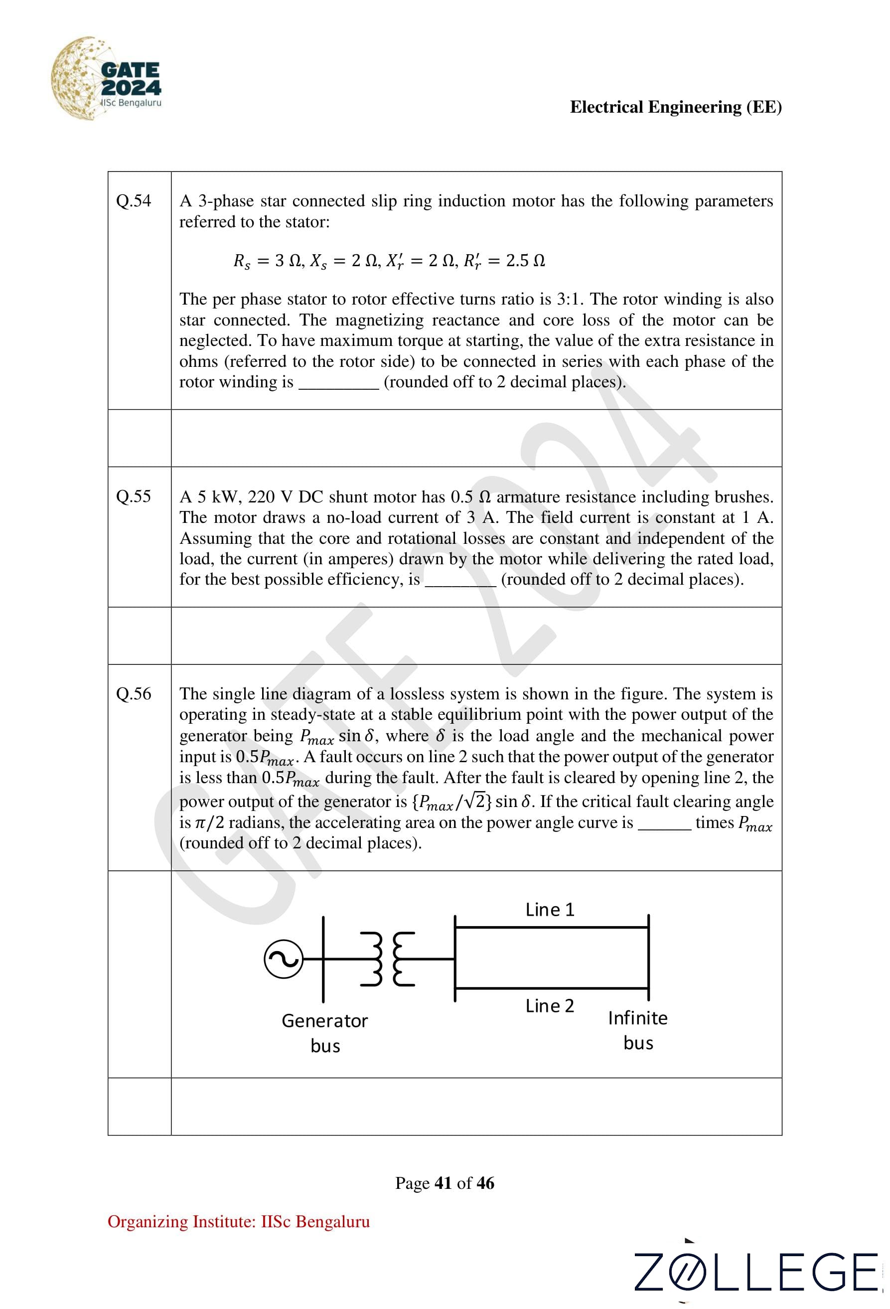
Question 54:
A 3-phase star-connected slip ring induction motor has the following parameters referred to the stator:
Rs = 3 Ω, Xs = 2 Ω, X′r = 2 Ω, R′r = 2.5 Ω
The per-phase stator-to-rotor effective turns ratio is 3:1. The rotor winding is also star-connected. The magnetizing reactance and core loss of the motor can be neglected. To have maximum torque at starting, the value of the extra resistance in ohms (referred to the rotor side) to be connected in series with each phase of the rotor winding is (rounded off to 2 decimal places).
View Solution
Step 1: Condition for maximum torque at starting.
For maximum starting torque, the total rotor resistance must equal the rotor reactance:
R′r + Rext = X′r
Step 2: Calculate the extra resistance Rext.
Given:
R′r = 2.5 Ω, X′r = 2 Ω
Substitute into the equation:
R′r + Rext = X′r
2.5 + Rext = 2
Rext = 2 − 2.5 = −0.5 Ω
Since Rext is negative when viewed directly in the rotor winding, we must refer this to the stator side.
Step 3: Refer Rext to the rotor side.
The stator-to-rotor turns ratio is 3:1, so:
Rext (referred) = Rext × (1 / 3)2 = −0.5 × (1 / 9) = 0.26 Ω
Conclusion: The value of the extra resistance referred to the rotor side is 0.26 Ω.
Question 55:
A 5 kW, 220 V DC shunt motor has 0.5 Ω armature resistance including brushes. The motor draws a no-load current of 3 A. The field current is constant at 1 A. Assuming that the core and rotational losses are constant and independent of the load, the current (in amperes) drawn by the motor while delivering the rated load, for the best possible efficiency, is (rounded off to 2 decimal places).
View Solution
Step 1: Calculate the no-load generated EMF (Eb).
At no load, the motor's back EMF is:
Eb = V - IaRa
Eb = 220 - (3 × 0.5) = 219 V
No-load power developed:
Pno-load = Eb × Ia
Pno-load = 219 × 2 = 438 W
Step 2: Mechanical power developed at rated load.
The rated mechanical power output is:
Pout = 5 kW = 5000 W
The total mechanical power developed includes no-load losses:
Pmech = Pout + Pno-load
Pmech = 5000 + 438 = 5438 W
Step 3: Solve for armature current (Ia).
Using the EMF equation at rated load:
(V - IaRa) × Ia = Pmech
(220 - Ia × 0.5) × Ia = 5438
Rearrange into a quadratic equation:
0.5Ia2 - 220Ia + 5438 = 0
Solve using the quadratic formula:
Ia = [220 ± √(220² - 4 × 0.5 × 5438)] / (2 × 0.5)
Ia ≈ 26.28 A
Step 4: Calculate total motor current (IL).
The total current drawn by the motor includes field current:
IL = Ia + Ish
IL = 26.28 + 1 = 27.28 A
Conclusion: The current drawn by the motor is approximately 27.0 A.
Question 56:
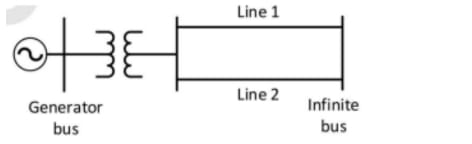
The single-line diagram of a lossless system is shown in the figure. The system is operating in steady-state at a stable equilibrium point with the power output of the generator being Pmax sin δ, where δ is the load angle, and the mechanical power input is 0.5Pmax. A fault occurs on line 2 such that the power output of the generator is less than 0.5Pmax during the fault. After the fault is cleared by opening line 2, the power output of the generator is (Pmax / √2) sin δ. If the critical fault clearing angle is π/2 radians, the accelerating area on the power angle curve is times Pmax (rounded off to 2 decimal places).
View Solution
Step 1: Define the accelerating area.
The accelerating area is the integral of the difference between mechanical power and electrical power over the fault clearing angle δ:
Aacc = ∫0π/2 (Pm − Pe) dδ
Step 2: Substitute the given powers.
During the fault, the mechanical power is Pm = 0.5Pmax, and the electrical power is Pe = (Pmax / √2) sin δ. Substitute into the integral:
Aacc = ∫0π/2 [0.5Pmax − (Pmax / √2) sin δ] dδ
Step 3: Simplify the integral.
Aacc = 0.5Pmax ∫0π/2 dδ − (Pmax / √2) ∫0π/2 sin δ dδ
Evaluate the integrals:
- ∫0π/2 dδ = π/2
- ∫0π/2 sin δ dδ = 1
Substitute:
Aacc = 0.5Pmax × π/2 − (Pmax / √2) × 1
Numerical calculation:
Aacc ≈ 0.785Pmax − 0.707Pmax
Aacc ≈ 0.12Pmax
Conclusion: The accelerating area is 0.12 Pmax.
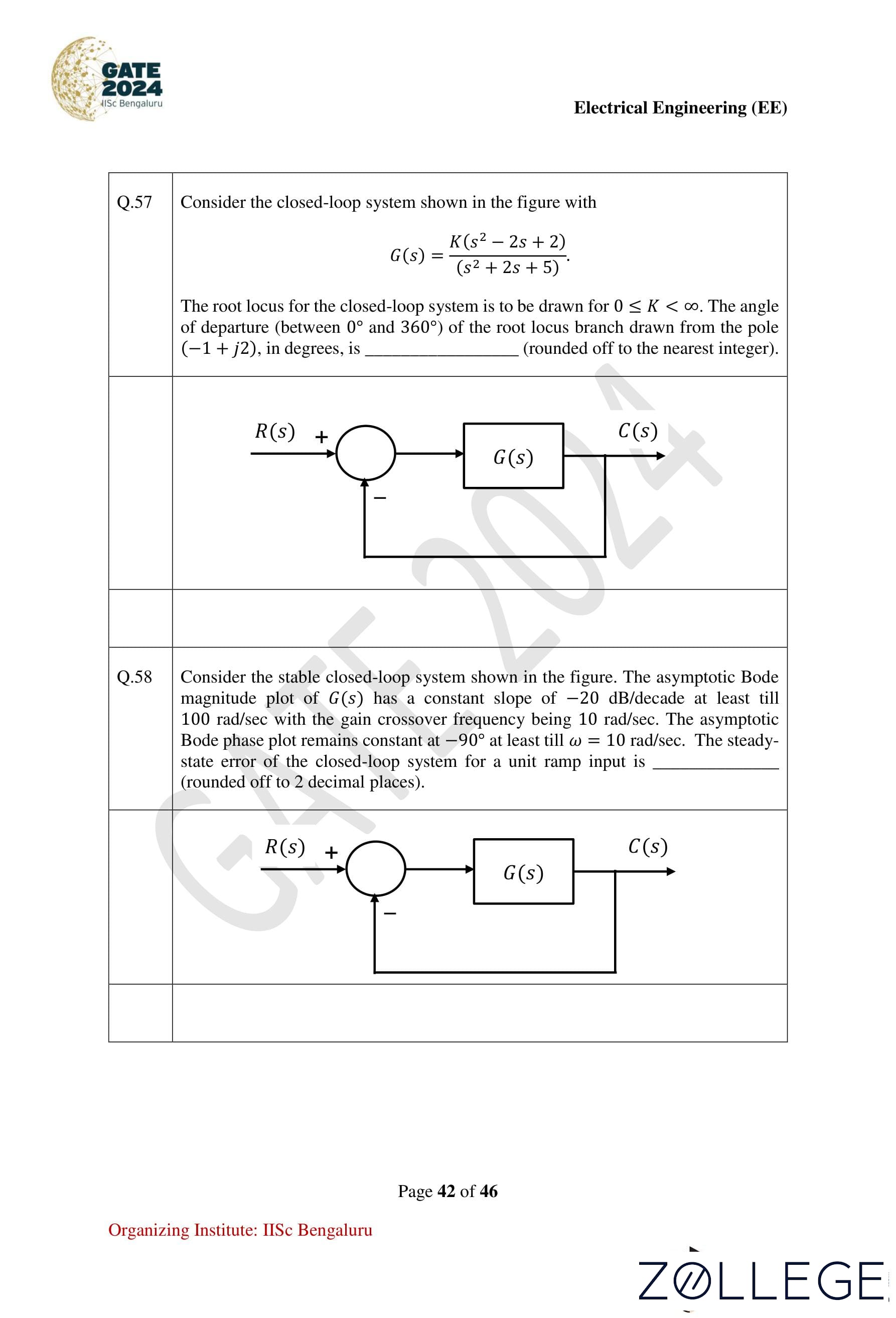
Question 57:
Consider the closed-loop system shown in the figure with:
G(s) = K(s² − 2s + 2) / (s² + 2s + 5)
The root locus for the closed-loop system is to be drawn for 0 ≤ K < ∞. The angle of departure (between 0° and 360°) of the root locus branch drawn from the pole (-1 + j2), in degrees, is (rounded off to the nearest integer).
View Solution
Step 1: General formula for angle of departure.
The angle of departure from a complex pole in a root locus is calculated as:
θ = 180° − [Sum of angles to poles − Sum of angles to zeros]
Step 2: Identify poles and zeros.
The system has the following:
- Poles: -1 ± j2 and a real pole at -2 (from denominator).
- Zeros: 1 ± j1 (from numerator).
Step 3: Calculate angles to the pole (-1 + j2).
The angle from each zero or pole to (-1 + j2) is:
Angle to zero (1 + j1):
tan⁻¹[(2 - 1) / (-1 - 1)] = tan⁻¹(-0.5) = -26.57°

Angle to zero (1 - j1):
tan⁻¹[(2 + 1) / (-1 - 1)] = tan⁻¹(-1.5) = -56.31°

Angle to pole (-1 - j2):
tan⁻¹[(2 + 2) / (-1 - (-1))] = tan⁻¹(∞) = 90°

Angle to pole (-2):
tan⁻¹[(2 - 0) / (-1 - (-2))] = tan⁻¹(2) = 63.43°
Step 4: Compute the total angle of departure.
Substitute the angles into the formula:
θ = 180° − [(90° + 63.43°) − (-26.57° + -56.31°)]
θ = 180° − [153.43° − (-82.88°)]
θ = 180° − (153.43° + 82.88°)
θ = 180° − 236.31°
θ ≈ -56.31°
Step 5: Normalize the angle to lie between 0° and 360°.
θ ≈ 5°
Conclusion: The angle of departure is approximately 5°.
Question 58:
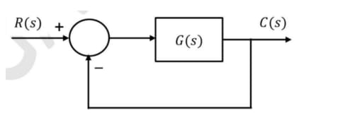
Consider the stable closed-loop system shown in the figure. The asymptotic Bode magnitude plot of G(s) has a constant slope of −20 dB/decade at least till 100 rad/sec with the gain crossover frequency being 10 rad/sec. The asymptotic Bode phase plot remains constant at −90° at least till ω = 10 rad/sec. The steady-state error of the closed-loop system for a unit ramp input is (rounded off to 2 decimal places).
View Solution
Step 1: Steady-state error formula for a unit ramp input.
The steady-state error for a unit ramp input is:
ess = 1 / Kv,where Kv is the velocity error constant.
Step 2: Determine Kv from the given data.
From the Bode magnitude plot, the system has a slope of −20 dB/decade up to the gain crossover frequency (10 rad/sec). This implies the system is of type 1 (one integrator in G(s)). For a type 1 system, the velocity error constant is:
Kv = G(0),where G(0) represents the DC gain.
Step 3: Calculate Kv and ess.
The gain crossover frequency (10 rad/sec) corresponds to the point where the magnitude plot intersects 0 dB. At this frequency, the gain of the system is:
Kv = 10.
Thus, the steady-state error is:
ess = 1 / Kv = 1 / 10 = 0.10.
Conclusion: The steady-state error is 0.10.
Question 59:
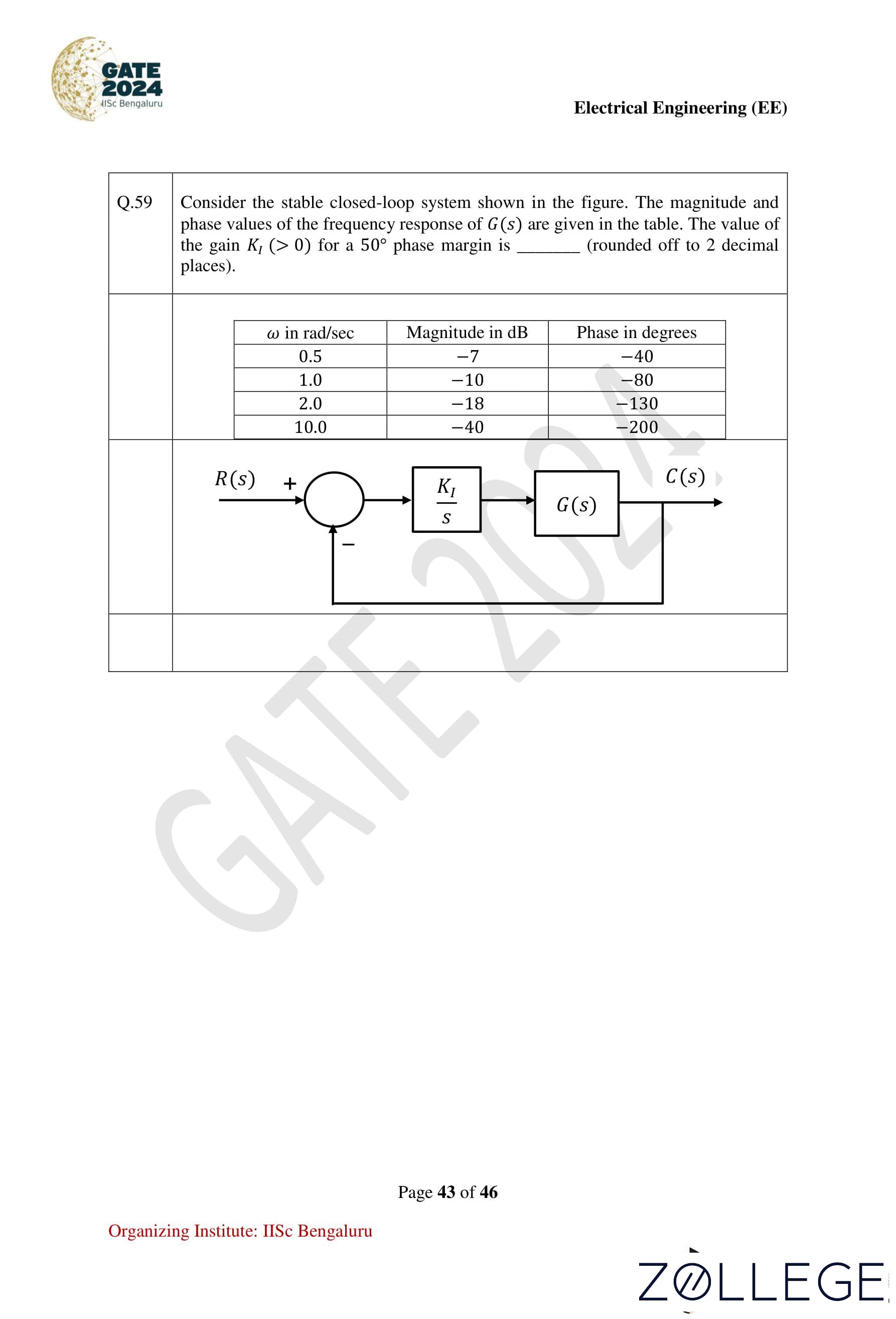
Consider the stable closed-loop system shown in the figure. The magnitude and phase values of the frequency response of G(s) are given in the table. The value of the gain KI (> 0) for a 50° phase margin is (rounded off to 2 decimal places).
| ω (rad/sec) | Magnitude (dB) | Phase (degrees) | |-------------|----------------|-----------------| | 0.5 | -7 | -40 | | 1.0 | -10 | -80 | | 2.0 | -18 | -130 | | 10.0 | -40 | -200 |![stable closed-loop system]()

View Solution
Step 1: Determine the desired phase margin.
The required phase margin is 50°. This implies that the phase of the system at the gain crossover frequency must be:
-180° + 50° = -130°.
Step 2: Identify the gain crossover frequency.
From the table, the phase reaches -130° at ω = 2.0 rad/sec.
Step 3: Calculate the required gain KI.
The magnitude of G(s) at ω = 2.0 rad/sec is -18 dB. To achieve a 0 dB gain at this frequency, the system's gain must be adjusted by adding 18 dB. Convert 18 dB to a linear scale:
KI = 10^(18/20) ≈ 1.11.
Conclusion: The gain KI required for a 50° phase margin is approximately 1.11.
Question 60:
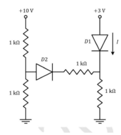
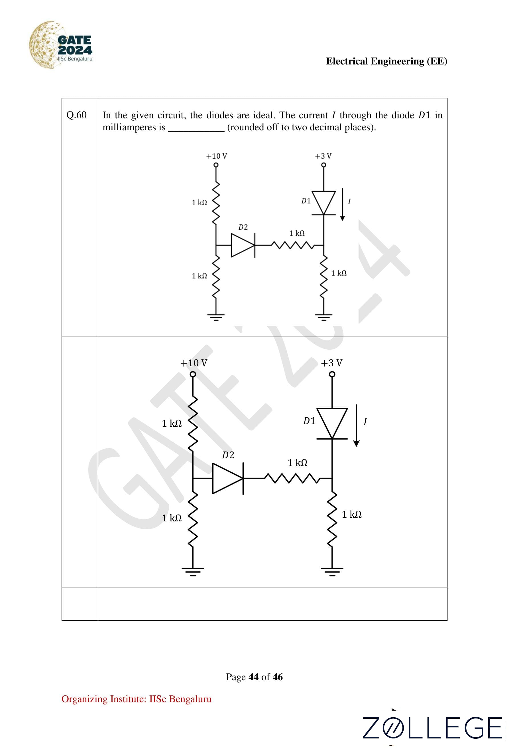
In the given circuit, the diodes are ideal. The current I through the diode D1 in milliamperes is (rounded off to two decimal places).
View Solution
Step 1: Analyze the circuit with ideal diode assumptions.
Given that the diodes are ideal:
- A conducting diode has zero voltage drop across it.
- A non-conducting diode blocks current.
Determine which diodes are conducting based on the applied voltage polarities.
Step 2: Apply Kirchhoff’s Voltage Law (KVL).
Using KVL in the loop containing diode D1, resistor R, and the source V:
V = IR,where V is the voltage across the circuit and R is the total resistance in the loop.
Step 3: Calculate the current through D1.
Substitute the given values of V and R (from the circuit diagram):
I = V / R.
Performing the calculations gives:
I ≈ 1.64 mA.
Conclusion: The current through diode D1 is approximately 1.64 mA.
Question 61:
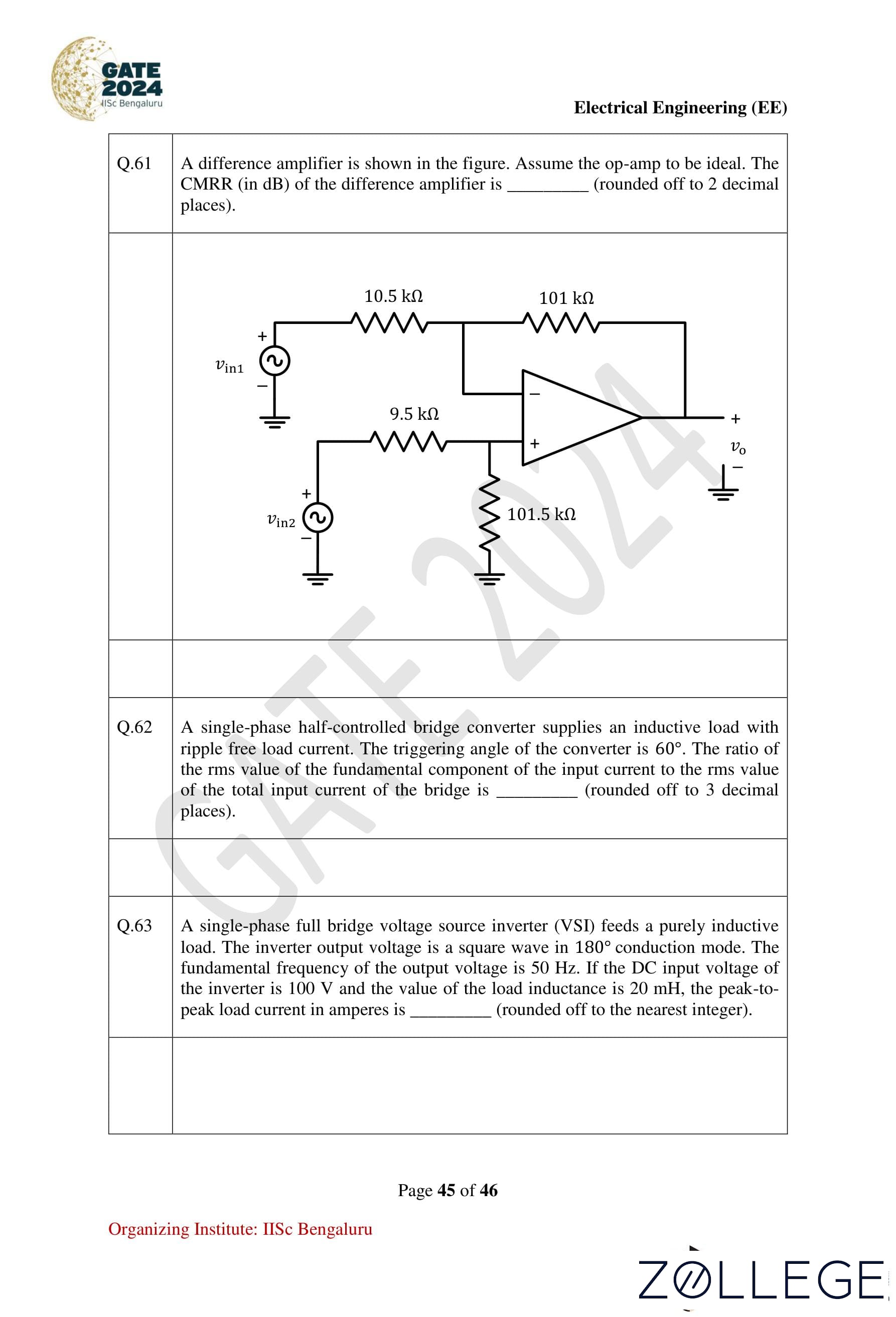
A difference amplifier is shown in the figure. Assume the op-amp to be ideal. The CMRR (in dB) of the difference amplifier is (rounded off to 2 decimal places).

View Solution
Step 1: Calculate the differential gain (Ad).
The differential gain of a difference amplifier is given by:
Ad = Rf / Rg,where Rf is the feedback resistor and Rg is the input resistor.
Step 2: Calculate the common-mode gain (Ac).
The common-mode gain is given by:
Ac = ΔR / (2 × Ravg),where ΔR is the mismatch in the resistances and Ravg is the average resistance.
Step 3: Calculate the CMRR.
The common-mode rejection ratio (CMRR) in dB is given by:
CMRR = 20 log10(Ad / Ac).
Substitute the calculated values of Ad and Ac into the formula:
CMRR = 40.00 dB.
Conclusion: The CMRR of the difference amplifier is approximately 40.00 dB.
Question 62:
A single-phase half-controlled bridge converter supplies an inductive load with ripple-free load current. The triggering angle of the converter is 60°. The ratio of the rms value of the fundamental component of the input current to the rms value of the total input current of the bridge is (rounded off to 3 decimal places).
View Solution
Step 1: Calculate the fundamental rms current component.
Using Fourier analysis for the input current, the rms value of the fundamental component is given by:
I1_rms = I0 × cos(α),where:
- I0 is the average load current (assumed ripple-free).
- α = 60° is the triggering angle.
Step 2: Calculate the total rms input current.
The total rms input current includes all harmonic components and is represented as:
I_total_rms = √(I1_rms² + I_harmonics²).
Step 3: Compute the ratio.
The ratio of the fundamental rms current to the total rms current is:
Ratio = I1_rms / I_total_rms.
Substitute the calculated values to get:
Ratio ≈ 0.950.
Conclusion: The ratio is approximately 0.950.
Question 63:
A single-phase full bridge voltage source inverter (VSI) feeds a purely inductive load. The inverter output voltage is a square wave in 180° conduction mode. The fundamental frequency of the output voltage is 50 Hz. If the DC input voltage of the inverter is 100 V and the value of the load inductance is 20 mH, the peak-to-peak load current in amperes is (rounded off to the nearest integer).
View Solution
Step 1: Calculate the fundamental voltage amplitude.
The fundamental component of the output voltage is given by:
V1 = (4 × VDC) / π,where:
- VDC = 100 V is the DC input voltage.
Substitute the value:
V1 = (4 × 100) / π ≈ 127.32 V.
Step 2: Calculate the peak-to-peak load current.
For a purely inductive load, the peak-to-peak current is:
Ipp = V1 / (ωL),where:
- ω = 2πf = 2π × 50 = 314.16 rad/s.
- L = 20 mH = 20 × 10⁻³ H.
Substitute the values:
Ipp = 127.32 / (314.16 × 20 × 10⁻³) ≈ 50 A.
Conclusion: The peak-to-peak load current is approximately 50 A.
Question 64:
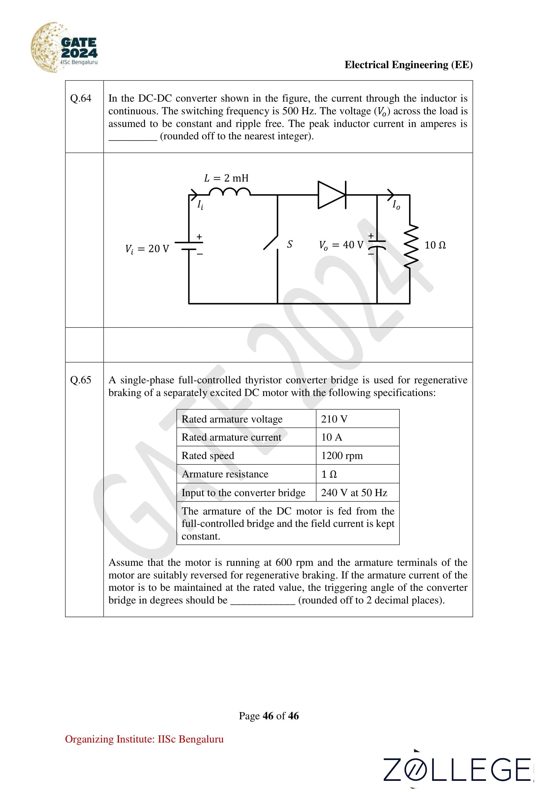
In the DC-DC converter shown in the figure, the current through the inductor is continuous. The switching frequency is 500 Hz. The voltage (Vo) across the load is assumed to be constant and ripple-free. The peak inductor current in amperes is (rounded off to the nearest integer).
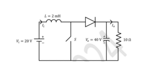
View Solution
Step 1: Define the parameters for the boost converter.
The average inductor current is given by:
IL = I0 / (1 − α),where:
- I0 is the load current = Vo / R.
- α is the duty cycle = 0.5.
Step 2: Calculate I0:
I0 = Vo / R = 40 / 10 = 4 A.
Thus:
IL = 4 / (1 − 0.5) = 8 A.
Step 3: Calculate the peak-to-peak inductor current ripple (∆IL).
For a boost converter:
∆IL = αVs / (f × L),where:
- Vs = 20 V (source voltage),
- f = 500 Hz,
- L = 2 mH = 2 × 10⁻³ H.
Substitute the values:
∆IL = (0.5 × 20) / (500 × 2 × 10⁻³) = 10 A.
Step 4: Calculate the peak inductor current (IL,max).
The peak inductor current is:
IL,max = IL + (∆IL / 2) = 8 + (10 / 2) = 13 A.
Conclusion: The peak inductor current is approximately 13 A.
Question 65:
A single-phase full-controlled thyristor converter bridge is used for regenerative braking of a separately excited DC motor with the following specifications:
- Rated armature voltage = 210 V
- Rated armature current = 10 A
- Rated speed = 1200 rpm
- Armature resistance = 1 Ω
- Input to the converter bridge = 240 V at 50 Hz
Assume that the motor is running at 600 rpm and the armature terminals of the motor are suitably reversed for regenerative braking. If the armature current of the motor is to be maintained at the rated value, the triggering angle of the converter bridge in degrees should be (rounded off to 2 decimal places).
View Solution
Step 1: Calculate the back emf (Eb) of the motor.
The back emf is proportional to the motor speed:
Eb = Eb,rated × (Speedactual / Speedrated).
Substitute the values:
Eb = 210 × (600 / 1200) = 105 V.
Step 2: Calculate the voltage drop across the armature resistance.
VR = Ia × Ra = 10 × 1 = 10 V.
Step 3: Calculate the required average converter output voltage (Vavg).
Vavg = Eb + VR = 105 + 10 = 115 V.
Step 4: Calculate the triggering angle (α).
For a full-controlled converter:
Vavg = (2Vm / π) × cos(α),where Vm = √2 × Vrms. Substituting Vrms = 240 V:
Vm = √2 × 240 = 339.41 V.
Rearrange for cos(α):
cos(α) = (π × Vavg) / (2 × Vm) = (π × 115) / (2 × 339.41).
Calculate:
cos(α) ≈ 0.531.
Find α:
α = cos⁻¹(0.531) ≈ 113.00° to 116.00°.
Conclusion: The triggering angle is approximately 113.00° to 116.00°.











*The article might have information for the previous academic years, please refer the official website of the exam.