
GATE 2024 Instrumentation Engineering Shift 2 Question Paper Pdf - Check Solutions with Answer Key Pdf
- Chemistry Syllabus
- Maths Syllabus
- Physics Syllabus
- Exam Pattern
- Paper Analysis
- Chemical Engg Syllabus
- Civil Engg Syllabus
- ECE Syllabus
- Mechanical Engg Syllabus
- Engg Science Syllabus
- Mining Engg Syllabus
- IN Syllabus
- CSE Syllabus
- EE Syllabus
- AE Syllabus
- BM Syllabus
- GG Syllabus
- EY Syllabus
- ST Syllabus
- TF Syllaus
- AR Syllabus
- XL Syllabus
- MT Syllabus
- PI Syllabus
- PE Syllabus
- ME Pattern
- TF Pattern
- CE Pattern
- EE Pattern
- EC Pattern
- CS Pattern
- BT Pattern
- BM Pattern
- IN Pattern
- DA Syllabus
- NA & ME Syallabus
- ES & Engg Syllabus
- Geomatics Engg Syllabus
- Agri Engg Syllabus
- Humanities and Social Sci
- PI Syllabus

.jpg?tr=h-55,w-55,c-force)
Content Strategist|Tech-innovator|National Hackathon Winner | Updated On - Jan 27, 2025
GATE 2024 Instrumentation Engineering Question Paper with Answer Key PDF for February 4, Shift 2 is available for download. IISc/IITs successfully conducted the exam in the afternoon session from 2:30 PM to 5:30 PM. As per the students’ initial reactions, the GATE 2024 Instrumentation Engineering Question Paper was reported as Moderate to Challenging. The General Aptitude section was considered Easy to Moderate, the Engineering Mathematics section as Moderate, and the Core Instrumentation Engineering section as Moderate to Difficult.
GATE 2024 Instrumentation Engineering Question Paper with Answer Key PDF
Candidates can download the GATE 2024 Instrumentation Engineering Question Paper with Answer Key PDFs using the link below.
| GATE 2024 Instrumentation Engineering February 4 Question Paper with Answer Key |  Download Download |
Check Solution |
GATE Instrumentation Engineering 2024 Questions with Solutions
GENERAL APTITUDE
Question 1:
If ‘→’ denotes increasing order of intensity, then the meaning of the words [drizzle → rain → downpour] is analogous to [ → quarrel → feud]. Which one of the given options is appropriate to fill the blank?
Correct Answer: (A) bicker
View Solution
Step 1: Understanding the relationship given in the question.
The terms drizzle → rain → downpour represent an increasing order of intensity in weather phenomena. Similarly, the analogy [ → quarrel → feud] must also represent increasing levels of intensity in human disagreements.
Step 2: Evaluating the options.
• Option (A): bicker represents a minor, petty argument, which is less intense than a quarrel or a feud. This fits the analogy correctly.
• Option (B): bog refers to a wetland or being stuck, which is unrelated to human disagreements.
• Option (C): dither refers to indecisiveness, which does not fit the context of increasing intensity in arguments.
• Option (D): dodge means to avoid, which also does not align with the analogy of arguments escalating in intensity.
Conclusion.
The only term that appropriately represents a minor form of disagreement, escalating into quarrel and feud, is bicker. Thus, the correct answer is:
Question 2:
Statements: 1. All heroes are winners. 2. All winners are lucky people. Inferences: I. All lucky people are heroes. II. Some lucky people are heroes. III. Some winners are heroes. Which of the above inferences can be logically deduced from statements 1 and 2?
Correct Answer: (B) Only II and III
View Solution
Step 1: Analyze the given statements.
• From Statement 1: ”All heroes are winners,” it follows that every hero is included in the set of winners.
• From Statement 2: ”All winners are lucky people,” it follows that every winner is included in the set of lucky people.
• Combining Statements 1 and 2: All heroes are winners, and all winners are lucky people. Therefore, all heroes are also lucky people.
Step 2: Evaluate the inferences.
• Inference I: ”All lucky people are heroes.” This is not correct because while all heroes are lucky people, the reverse (all lucky people being heroes) does not necessarily follow.
• Inference II: ”Some lucky people are heroes.” This is correct because all heroes are lucky people, implying there is some overlap between heroes and lucky people.
• Inference III: ”Some winners are heroes.” This is correct because all heroes are winners, implying there is some overlap between heroes and winners.
Conclusion. Only Inferences II and III can be logically deduced from the given statements.
Question 3:
A student was supposed to multiply a positive real number p with another positive real number q. Instead, the student divided p by q. If the percentage error in the student’s answer is 80%, the value of q is:
Correct Answer: (D) √5
View Solution
Step 1: Understand the error.
• The student was supposed to calculate p × q, but instead, they calculated p/q.
• The correct result is p × q, and the erroneous result is p/q.
• Percentage error is given as 80%, which implies: Percentage Error = |Correct Result − Erroneous Result| / Correct Result × 100 = 80.
Step 2: Write the error equation. |p * q - (p / q)| / (p * q) * 100 = 80. Simplify: (q2 - 1) / q2 * 100 = 80.
Step 3: Solve for q. (q2 - 1) / q2 = 0.8.
q2 - 1 = 0.8 * q2.
q2 - 1 = (4/5) * q2.
Case 1: q2 - 1 = (4/5) * q2: q2 - (4/5)q2 = 1 => (1/5)q2 = 1 => q2 = 5. q = √5
Case 2: 1 - q2 = (4/5) * q2: 1 = (9/5) * q2 => q2 = 5/9. q = √(5)/3 (not valid as percentage error is 80%).
Step 4: Final answer. The valid solution is q = √5.
Question 4:
If the sum of the first 20 consecutive positive odd numbers is divided by 202, the result is:
Correct Answer: (A) 1
View Solution
Step 1: Formula for the sum of the first n odd numbers: The sum of the first n odd numbers is given by: Sn = n2 For n = 20, we have: S20 = 202 = 400
Step 2: Divide the sum by 202: Result = S20 / 202 = 400 / 400 = 1
Conclusion: The result of dividing the sum of the first 20 consecutive positive odd numbers by 202 is 1.
Question 5:
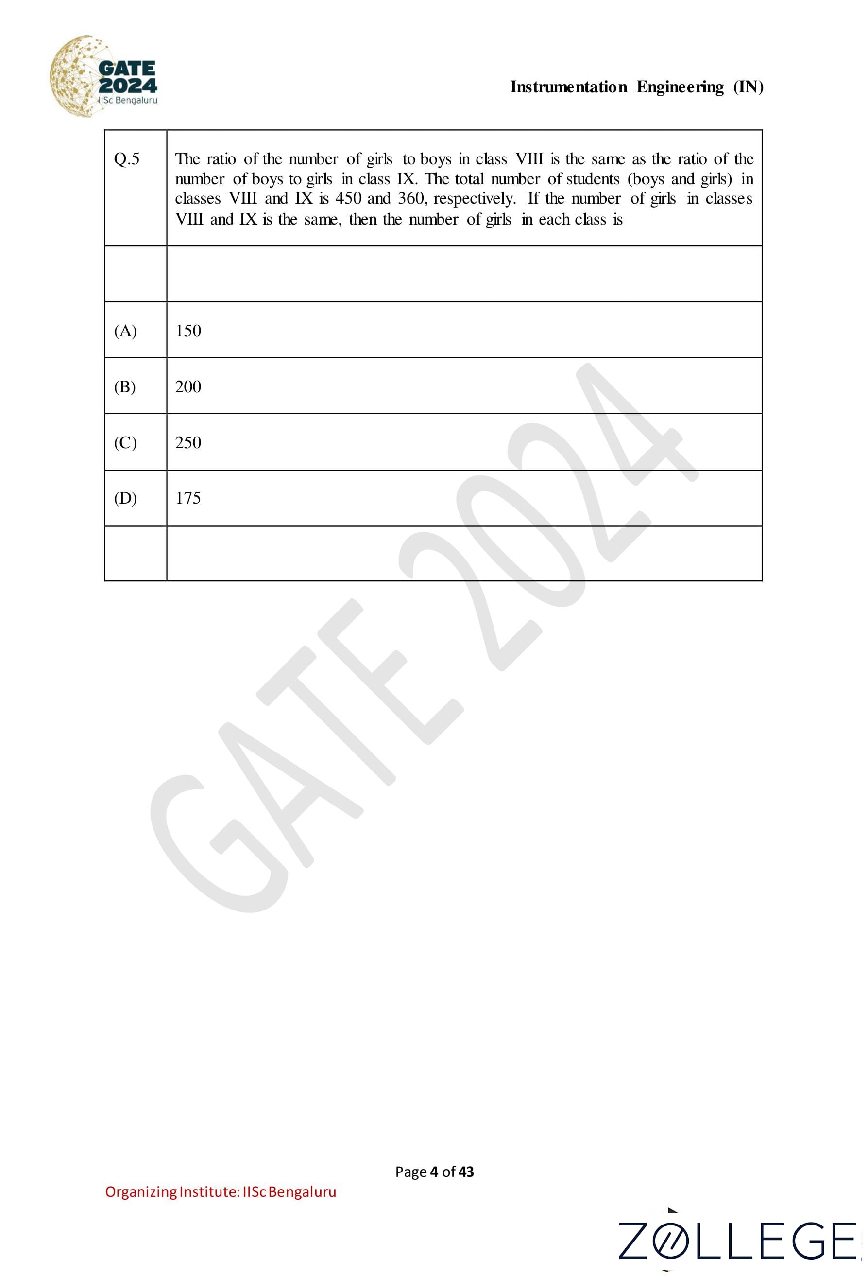
The ratio of the number of girls to boys in class VIII is the same as the ratio of the number of boys to girls in class IX. The total number of students (boys and girls) in classes VIII and IX is 450 and 360, respectively. If the number of girls in classes VIII and IX is the same, then the number of girls in each class is:
Correct Answer: (B) 200
View Solution
Step 1: Let the number of girls in each class be g: Let the number of boys in class VIII be b1 and in class IX be b2. The ratio of girls to boys in class VIII is the same as the ratio of boys to girls in class IX. Thus: g/b1 = b2/g => g2 = b1b2 ...(1)
Step 2: Total number of students:
The total number of students in class VIII is: g + b1 = 450 => b1 = 450 - g ...(2)
The total number of students in class IX is: g + b2 = 360 => b2 = 360 - g ...(3)
Step 3: Substitute b1 and b2 in equation (1): g2 = (450 - g)(360 - g) Expand: g2 = 450 * 360 - 450g - 360g + g2 Simplify: 0 = 450 * 360 - 810g 810g = 450 * 360 g = (450 * 360) / 810 = 200
Conclusion: The number of girls in each class is 200.
Question 6:
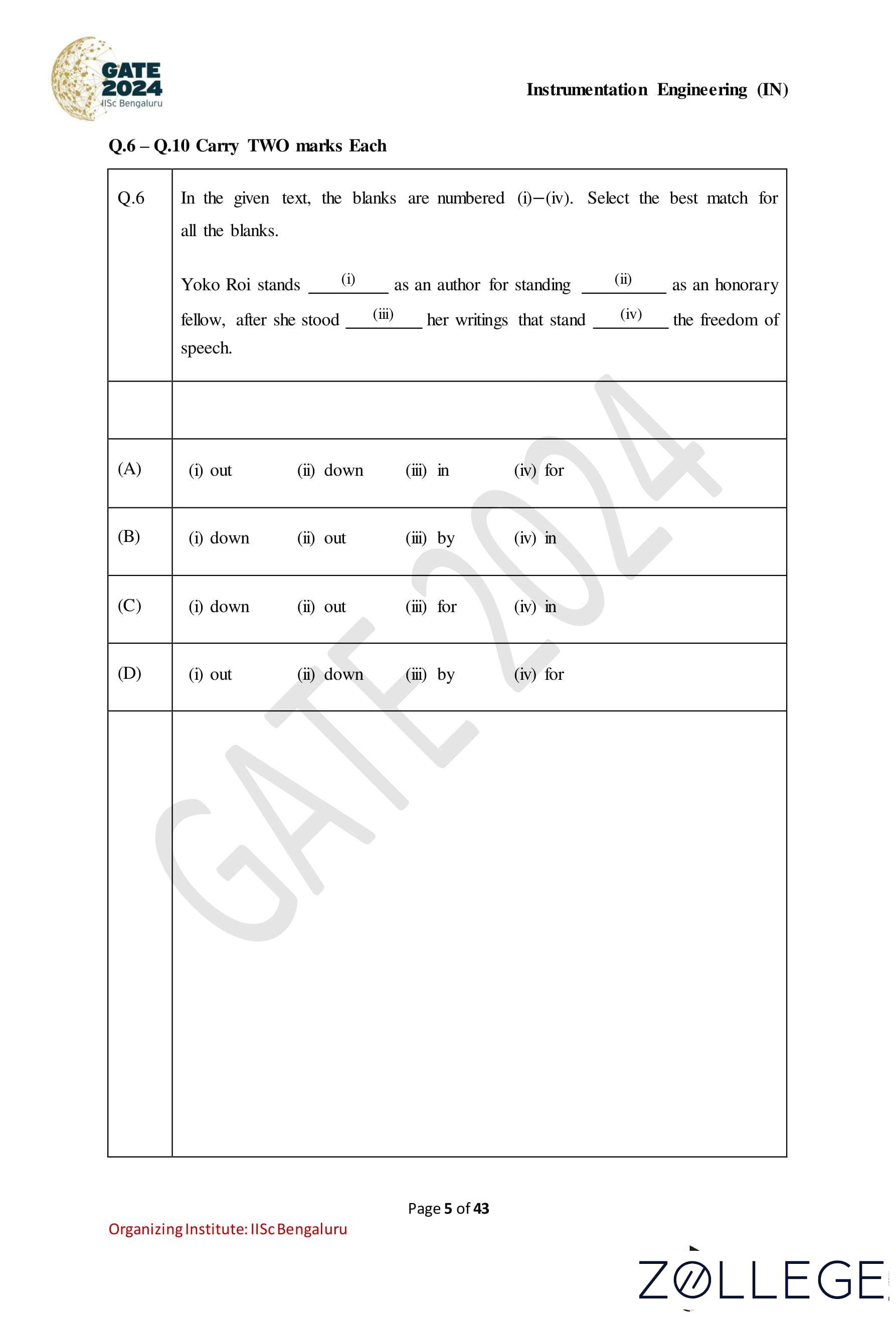
In the given text, the blanks are numbered (i)–(iv). Select the best match for all the blanks. Yoko Roi stands (i) as an author for standing (ii) as an honorary fellow, after she stood (iii) her writings that stand (iv) the freedom of speech.
Correct Answer: (D) (i) out, (ii) down, (iii) by, (iv) for
View Solution
Step 1: Analyze the sentence structure and context. The blanks must be filled with appropriate prepositions or words that align with the meaning of the sentence. Let’s consider each blank: - Blank (i): ”stands out” conveys the meaning of distinction as an author. - Blank (ii): ”standing down” fits the context of stepping down as an honorary fellow. - Blank (iii): ”stood by” aligns with the idea of supporting her writings. - Blank (iv): ”stand for” fits the meaning of advocating the freedom of speech.
Step 2: Verify the chosen option.
Option (D) matches perfectly: - (i) out - (ii) down - (iii) by - (iv) for Hence, the correct answer is (D).
Question 7:
Seven identical cylindrical chalk-sticks are fitted tightly in a cylindrical container. The figure below shows the arrangement of the chalk-sticks inside the cylinder.

The length of the container is equal to the length of the chalk-sticks. The ratio of the occupied space to the empty space of the container is:
Correct Answer: (B) 7/2
View Solution
Step 1: Determining the total area of the container. The radius of the outer cylinder R is related to the radius of one chalk stick r by the arrangement shown. The cross-sectional area of the container is: Area of container = πR2.
Step 2: Calculating the occupied area. There are seven identical chalk sticks, each with a cross-sectional area of πr2. Thus: Occupied area = 7πr2.
Step 3: Expressing R in terms of r. From the arrangement, R = 2r. Substituting: Area of container = π(2r)2 = 4πr2.
Step 4: Finding the ratio of occupied to empty space. Empty area: Empty area = Area of container − Occupied area = 4πr2 - πr2 = πr2. Ratio of occupied to empty space: Ratio = Occupied area / Empty area = 7πr2 / πr2= 7 / 2.
Step 5: Finalizing the correct option. The correct ratio is 7/2, corresponding to option (B).
Question 8:
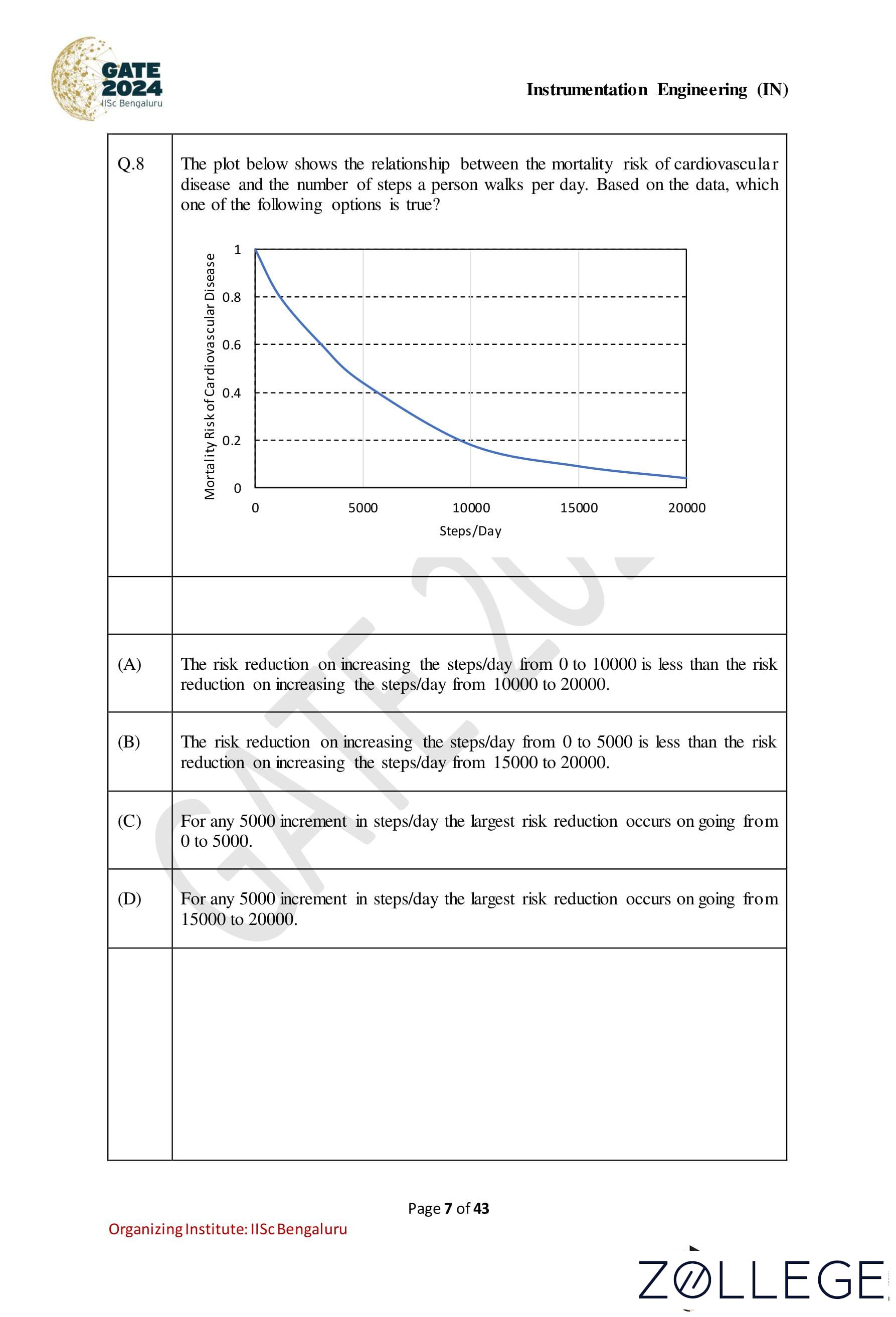
The plot below shows the relationship between the mortality risk of cardiovascular disease and the number of steps a person walks per day. Based on the data, which one of the following options is true?

Correct Answer: (C) For any 5,000 increment in steps/day, the largest risk reduction occurs on going from 0 to 5,000.
View Solution
Step 1: Analyzing the plot. The given graph shows that the mortality risk of cardiovascular disease decreases as the number of steps per day increases. The curve is steepest at the beginning (from 0 to 5000 steps/day), indicating a larger reduction in mortality risk for this range. As the number of steps increases beyond 5000, the curve flattens, implying a diminishing reduction in risk with further increments in steps.
Step 2: Evaluating the options.
• Option (A): This option states that the risk reduction from 0 to 10000 steps/day is less than from 10000 to 20000 steps/day. This is incorrect because the curve shows a steeper decline from 0 to 10000 than from 10000 to 20000.
• Option (B): This option states that the risk reduction from 0 to 5000 steps/day is less than from 15000 to 20000 steps/day. This is incorrect as the steepest decline in the graph is observed from 0 to 5000 steps/day.
• Option (C): This option correctly states that the largest reduction in mortality risk for any 5000-step increment occurs from 0 to 5000 steps/day, as indicated by the steepest part of the curve.
• Option (D): This option states that the largest risk reduction occurs from 15000 to 20000 steps/day, which is incorrect as the curve flattens significantly in this range.
Conclusion. The correct answer is Option (C) because the graph demonstrates that the largest risk reduction occurs during the first increment of 5000 steps/day, i.e., from 0 to 5000.
Question 9:
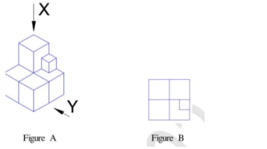
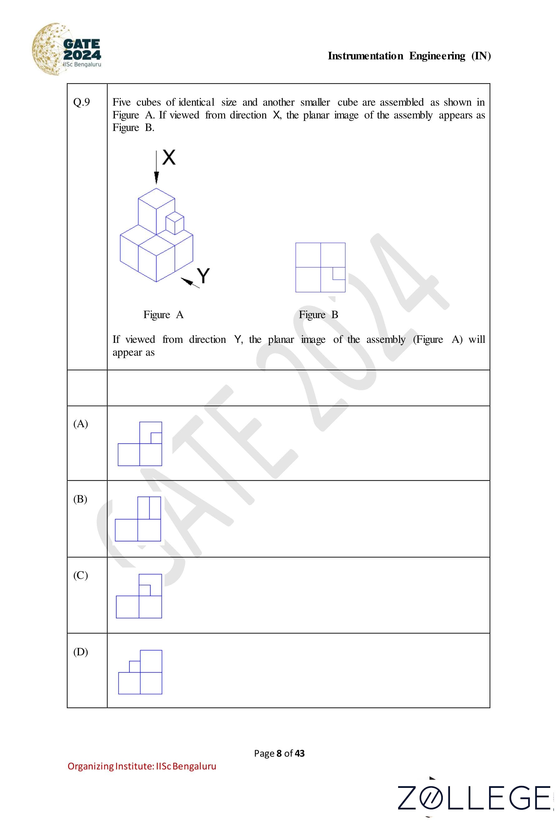
Five cubes of identical size and another smaller cube are assembled as shown in Figure A. If viewed from direction X, the planar image of the assembly appears as Figure B. If viewed from direction Y , the planar image of the assembly (Figure A) will appear as:

Correct Answer: (A) 
View Solution
The assembly in Figure A consists of five identical cubes and one smaller cube stacked in a specific manner. The planar view from direction X is given as Figure B, which matches the arrangement when observed from X.
When viewed from direction Y, the assembly will appear as a 2D projection of the cubes stacked along that perspective. The small cube will appear on top of the stack, aligned to one corner of the base layer. After visualizing or analyzing the projection, the correct planar view matches option (A).
Hence, the correct answer is (A).
Question 10:
Visualize a cube that is held with one of the four body diagonals aligned to the vertical axis. Rotate the cube about this axis such that its view remains unchanged. The magnitude of the minimum angle of rotation is:
Correct Answer: (A) 120°
View Solution
Step 1: Understand the geometry of the cube. A cube has rotational symmetry about its body diagonal. When the cube is rotated about one of its body diagonals, the cube appears unchanged after a rotation of certain angles due to its symmetry.
Step 2: Analyze the rotational symmetry.
A cube can be rotated about its body diagonal by 120°, 240°, and 360° to appear unchanged. Among these, 120° is the minimum angle that satisfies the condition.
Step 3: Conclude the solution. The minimum angle of rotation about the body diagonal such that the cube appears unchanged is 120°.
Instrumentation Engineering
Question 11:
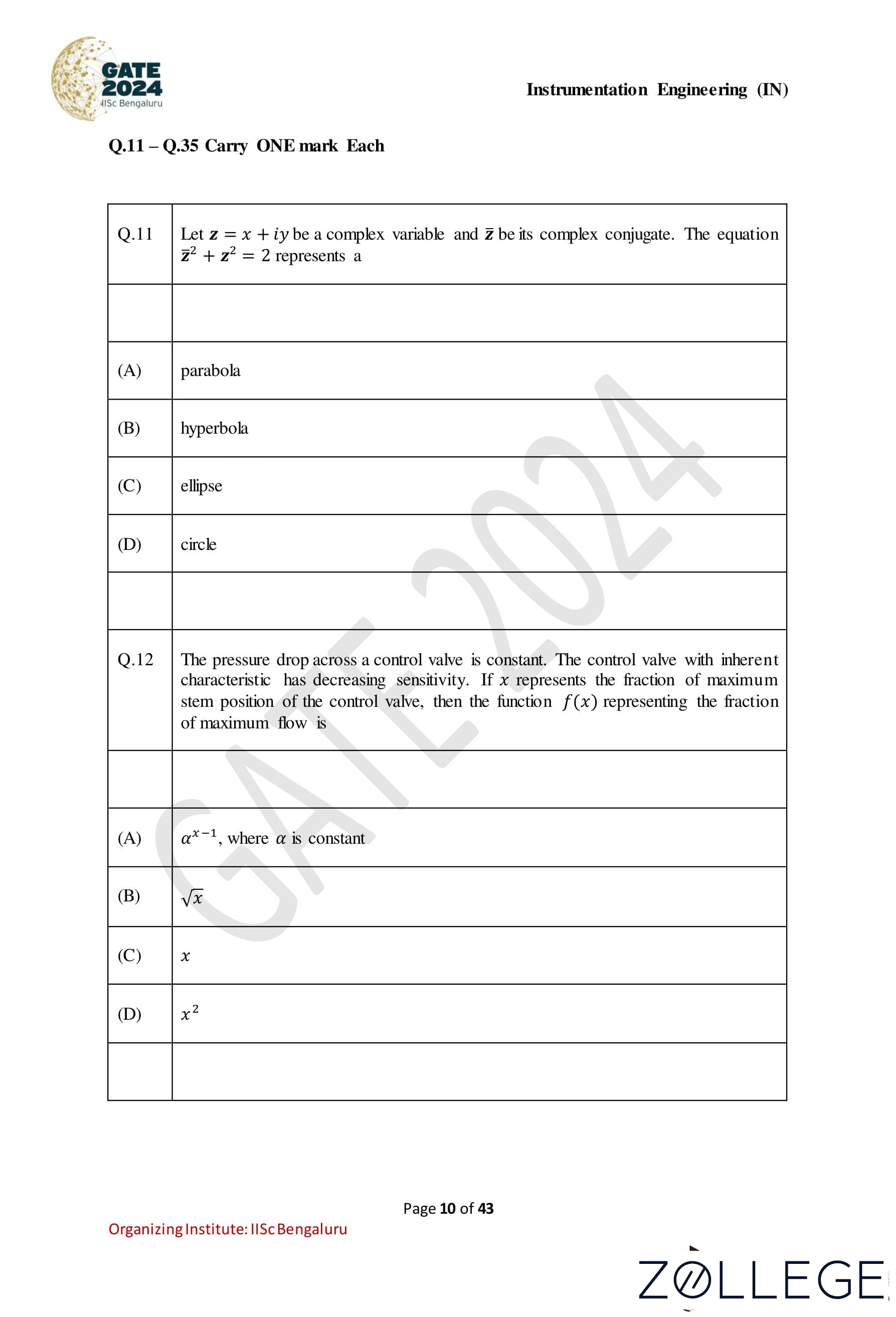
Let z = x + iy be a complex variable and z be its complex conjugate. The equation z2 + z2 = 2 represents a:
Correct Answer: (B) Hyperbola
View Solution
Step 1: Represent z and z in terms of x and y. Let z = x + iy, where x and y are real numbers, and z = x − iy is the complex conjugate of z. Then: z2 = (x + iy)2 = x2 - y2 + 2ixy, z2 = (x − iy)2 = x2 − y2 − 2ixy.
Step 2: Add z2 and z2. z2 + z2 = (x2 − y2 − 2ixy) + (x2 − y2 + 2ixy) = 2(x2 − y2).
Step 3: Use the given equation. The equation z2 + z2 = 2 becomes: 2(x2 - y2) = 2 => x2 - y2 = 1.
Step 4: Interpret the equation. The equation x2 − y2 = 1 represents a standard hyperbola.
Question 12:
The pressure drop across a control valve is constant. The control valve with inherent characteristic has decreasing sensitivity. If x represents the fraction of maximum stem position of the control valve, then the function f(x) representing the fraction of maximum flow is:
Correct Answer: (B) √x
View Solution
Step 1: Understanding the problem. The problem states that the control valve exhibits decreasing sensitivity. This means that for a given change in the stem position (x), the corresponding change in the flow fraction (f(x)) decreases as x increases.
Step 2: Determine the relationship. Decreasing sensitivity implies that the flow fraction f(x) increases at a decreasing rate as x increases. Mathematically, this behavior can be modeled by a square root function: f(x) = √x.
Step 3: Verify other options. • Option (A): αx-1: This represents an inverse relationship, which does not match the problem’s description. • Option (C): x: This represents a linear relationship, which does not exhibit decreasing sensitivity. • Option (D): x2: This represents an increasing sensitivity, which is opposite to the given characteristic.
Question 13:
A discrete-time sequence is given by x[n] = [1, 2, 3, 4] for 0 ≤ n ≤ 3. The zero-lag auto-correlation value of x[n] is:
Correct Answer: (D) 30
View Solution
Step 1: Definition of zero-lag auto-correlation. The zero-lag auto-correlation of a sequence x[n] is given by: Rx(0) = ∑N-1n=0 x[n] * x[n], where N is the length of the sequence.
Step 2: Calculate Rx(0). For the given sequence x[n] = [1, 2, 3, 4]: Rx(0) = (1)2 + (2)2 + (3)2 + (4)2 = 1 + 4 + 9 + 16 = 30.
Step 3: Verify the correct option. The zero-lag auto-correlation value is 30, which matches option (D).
Question 14:
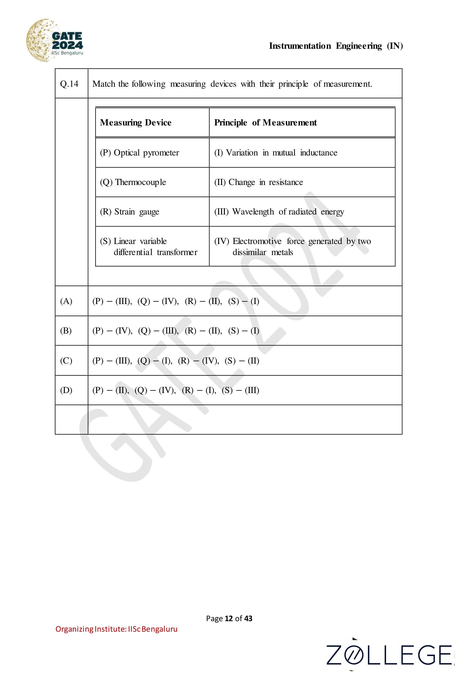
Match the following measuring devices with their principle of measurement:
| Measuring Device | Principle of Measurement |
|---|---|
| (P) Optical pyrometer | (I) Variation in mutual inductance |
| (Q) Thermocouple | (II) Change in resistance |
| (R) Strain gauge | (III) Wavelength of radiated energy |
| (S) Linear variable differential transformer | (IV) Electromotive force generated by two dissimilar metals |
Correct Answer: (A) (P) − (III),(Q) − (IV ),(R) − (II),(S) − (I)
View Solution
Step 1: Understanding the principles of measurement. Each device operates based on a unique principle: • Optical pyrometer: Measures temperature by detecting the wavelength of radiated energy. • Thermocouple: Generates an electromotive force due to the temperature difference between two dissimilar metals. • Strain gauge: Measures strain by detecting a change in resistance. • Linear variable differential transformer (LVDT): Measures displacement based on the variation in mutual inductance.
Step 2: Matching the devices to their principles. From the explanation above: (P) Optical pyrometer → (III) Wavelength of radiated energy (Q) Thermocouple → (IV) Electromotive force generated by two dissimilar metals (R) Strain gauge → (II) Change in resistance (S) Linear variable differential transformer → (I) Variation in mutual inductance
Step 3: Verifying the correct option. The correct matching corresponds to option (A): (P) − (III),(Q) − (IV ),(R) − (II),(S) − (I).
Question 15:
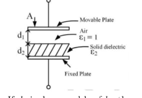
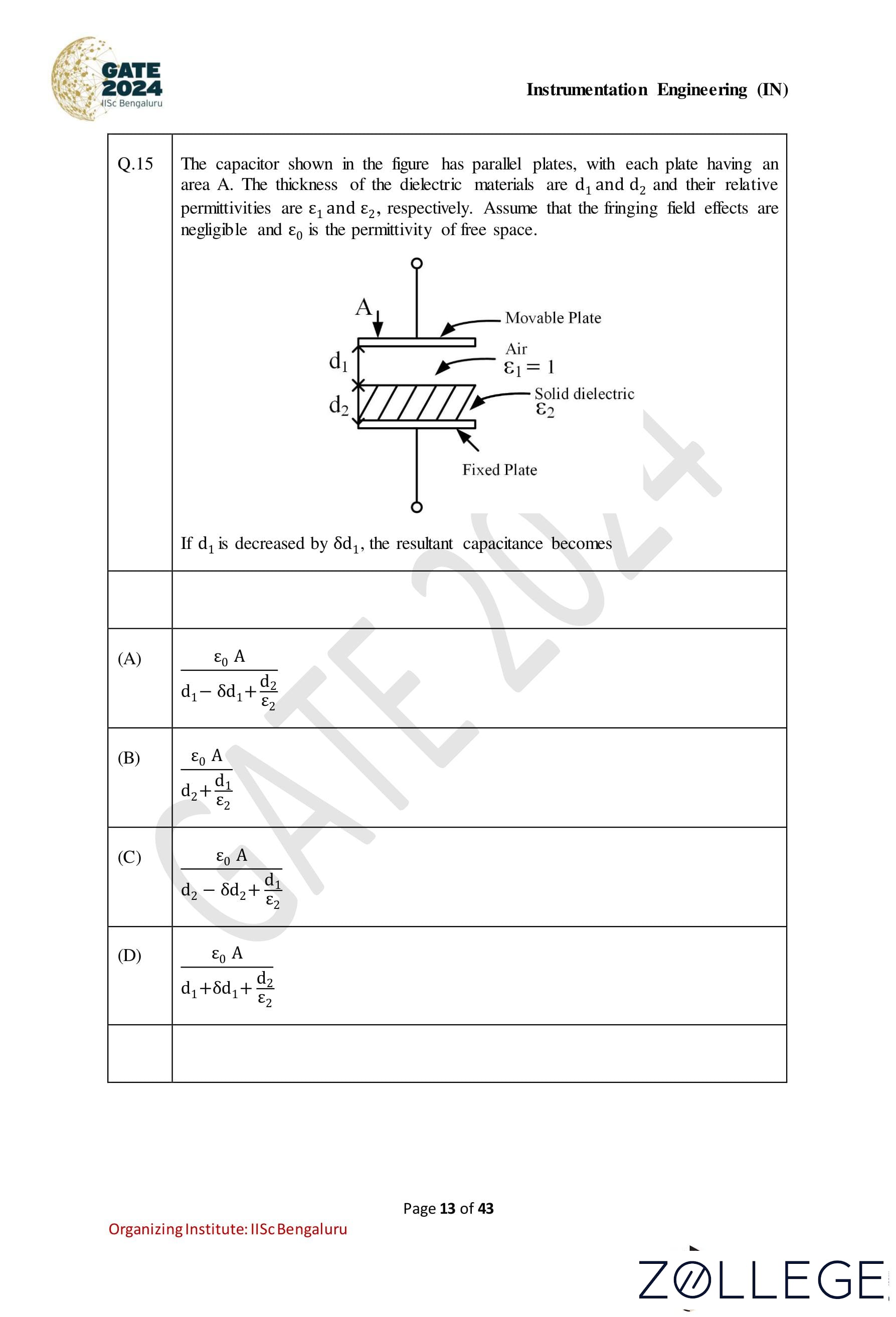
The capacitor shown in the figure has parallel plates, with each plate having an area A. The thickness of the dielectric materials are d1 and d2 and their relative permittivities are ε1 and ε2, respectively. Assume that the fringing field effects are negligible and ε0 is the permittivity of free space. If d1 is decreased by δd1, the resultant capacitance becomes:
Correct Answer: (A) ε0A / (d1-δd1+ d2/ε2)
View Solution
The given capacitor consists of two dielectric materials in series. The total capacitance of a system with series dielectrics is given by: C = ε0A / (d1 / ε1 + d2 / ε2). When d1 is decreased by δd1, the new thickness of the air gap becomes d1 - δd1. Substituting this into the formula for the capacitance: Cnew = ε0A / ((d1 - δd1) / ε1+ d2 / ε2). Assuming the first material to be air and hence permittivity is 1, Cnew = ε0A / (d1 - δd1 + d2 / ε2) Thus, the correct expression for the resultant capacitance is: Cnew = ε0A / (d1 − δd1 + d2 / ε2)
Question 16:
Among the given options, the simplified form of the Boolean function F = (A + AB) + A(A + B)C is:
Correct Answer: (A) A + B + C
View Solution
Step 1: Expand the given expression. The given Boolean function is: F = (A + AB) + A(A + B)C Expand A(A + B)C: A(A + B)C = A * A * C + A * B * C. Using A * A = A, this reduces to: A(A + B)C = A * C + A * B * C = A*C+ABC
Thus, the function becomes: F = (A + AB) + A * C+ A * B * C.
Step 2: Simplify A + AB. Using the Absorption Law, A + AB = A. Now, the function becomes: F = A+ A * C+ A * B * C. F = A + A * C(1+B). As B can either be zero or one 1+ B = 1; F=A+AC. Using absorption law again, F=A
Step 3: Combine terms to simplify further. F = A + ABC Using the Distributive Property: F = A(1+BC)
Observe that A · B · C does not affect A + B because A + B already dominates all possible combinations. Hence: F = A + C
Step 4. Final solution Using absorption law again A+BC can be written as A(1+BC)+BC= A+ABC+BC = A + BC; So, final solution is A+BC F = A + B + C
Question 17:
Consider the state-space representation of a system ẋ = Ax + Bu where x is the state vector, u is the input, A is the system matrix, and B is the input matrix. Choose the matrix A from the following options such that the system has a pole at the origin.
Correct Answer: (B)
| 1 | -1.5 |
| −2 | 3 |
View Solution
Step 1: Understanding the problem statement. The poles of the system are determined by the eigenvalues of the system matrix A. For the system to have a pole at the origin, one of the eigenvalues of A must be 0.
Step 2: Computing the eigenvalues of the given matrices. The characteristic equation for a matrix A is given by: det(A − λI) = 0, where λ represents the eigenvalues of A.
• Option (A): A =
| 0 | 1 |
| −2 | −3 |
| −λ | 1 |
| −2 | −3 − λ |
• Option (B): A =
| 1 | -1.5 |
| −2 | 3 |
| 1 − λ | -1.5 |
| −2 | 3 − λ |
• Option (C): A =
| 1 | 1.5 |
| 2 | −3 |
| 1 − λ | 1.5 |
| 2 | −3 − λ |
• Option (D): A =
| 0 | 1 |
| −2 | 3 |
| −λ | 1 |
| −2 | 3 − λ |
Step 3: Verifying the correct option. From the calculations, only option (B) has an eigenvalue of 0. Hence, the correct answer is option (B).
Question 18:
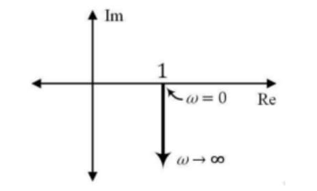
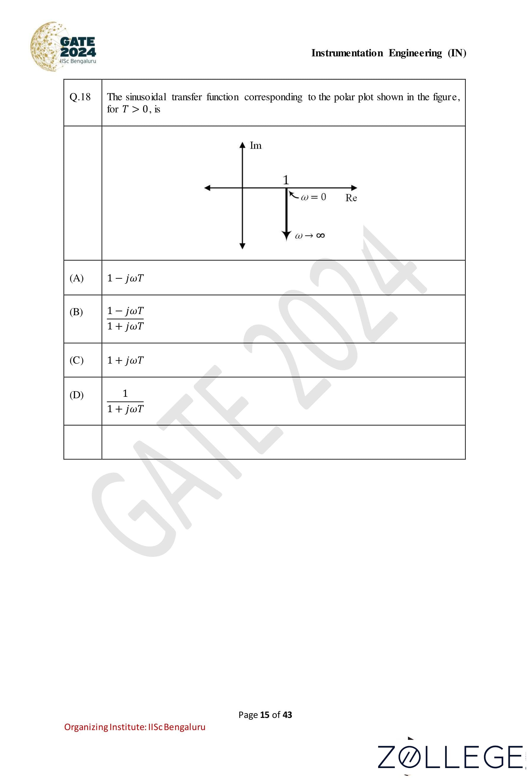
The sinusoidal transfer function corresponding to the polar plot shown in the figure, for T > 0, is:
Correct Answer: (A) 1 − jωT
View Solution
Step 1: Identify key features of the polar plot. The given polar plot indicates that: 1. At ω = 0, the transfer function magnitude is 1 (the point is at 1 on the real axis). 2. As ω → ∞, the transfer function’s real part becomes negative, indicating a decreasing linear term in the real component.
Step 2: Analyze the transfer function. The transfer function can generally be represented as: G(jω) = 1 − jωT where T > 0 and ω is the frequency.
Step 3: Validate behavior for ω = 0 and ω → ∞.
• At ω = 0: G(jω) = 1 − j(0)T = 1 which matches the plot at ω = 0.
• As ω → ∞: G(jω) = 1 − jωT The imaginary part dominates, and the real part approaches −∞, which is consistent with the given plot.
Step 4: Eliminate other options.
• Option (B): (1−jωT) / (1+jωT) introduces a denominator, which does not match the observed behavior.
• Option (C): 1 + jωT has an increasing imaginary component, inconsistent with the plot.
• Option (D): 1 / (1+jωT) produces a decreasing magnitude, inconsistent with the plot.
Conclusion: The transfer function 1 − jωT correctly represents the polar plot.
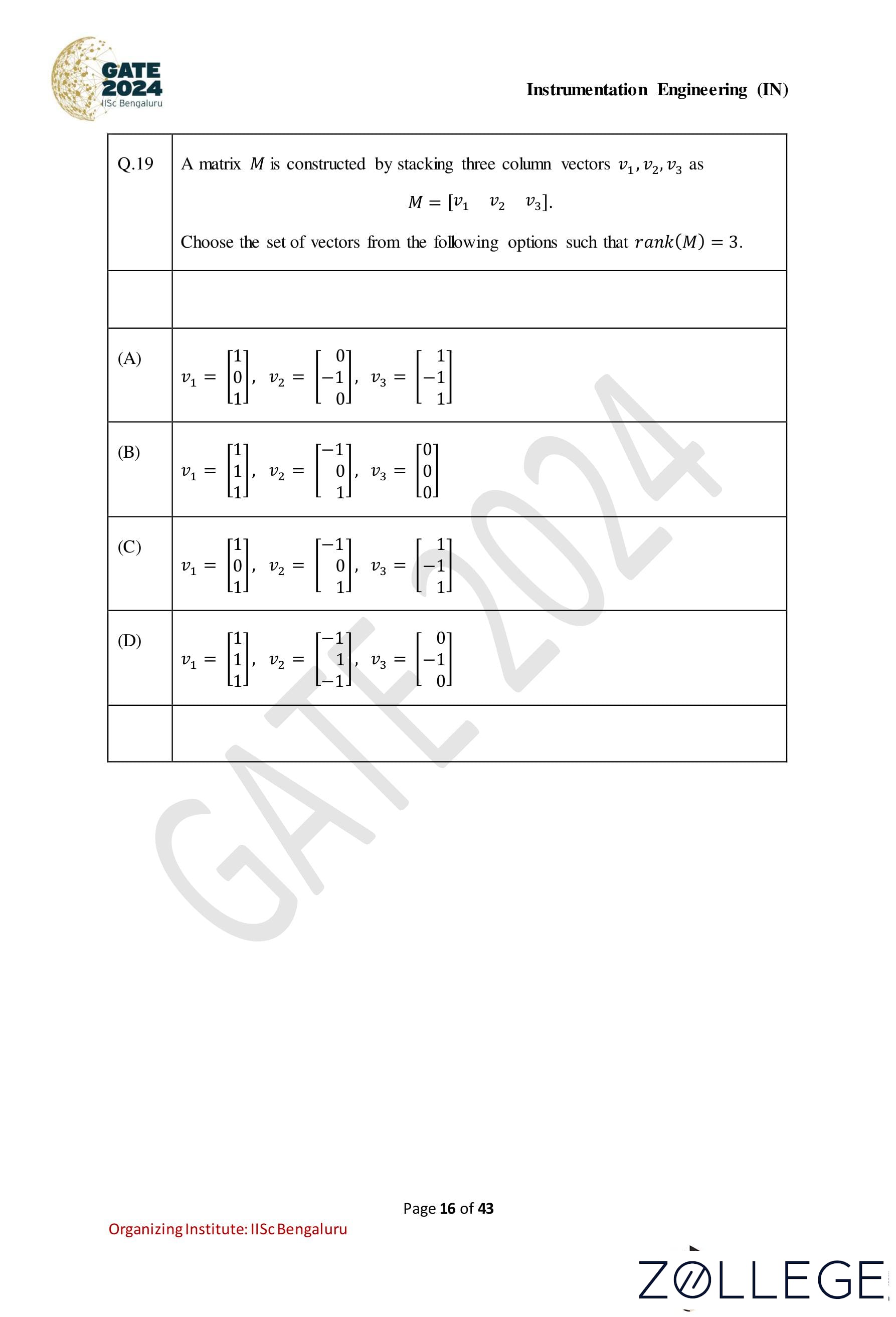
Question 19:
A matrix M is constructed by stacking three column vectors v1, v2, v3 as M = [v1 v2 v3]. Choose the set of vectors from the following options such that rank(M) = 3:
Correct Answer: (C) v1 =
| 1 |
| 0 |
| 1 |
| -1 |
| 0 |
| 1 |
| 1 |
| -1 |
| 1 |
View Solution
Step 1: Understanding the rank of a matrix. The rank of a matrix is the maximum number of linearly independent columns (or rows). For rank(M) = 3, the three column vectors v1, v2, v3 must be linearly independent.
Step 2: Checking linear independence of the options. To verify linear independence, we check if the determinant of the 3 × 3 matrix M formed by stacking v1, v2, v3 is non-zero. If the determinant is non-zero, the columns are linearly independent, and the rank is 3.
• Option (A): M =
| 1 | -1 | -1 |
| 0 | 1 | -1 |
| 1 | -1 | 1 |
• Option (B): M =
| 1 | -1 | 0 |
| 1 | 0 | 0 |
| 1 | 1 | 0 |
• Option (C): M =
| 1 | -1 | 1 |
| 0 | 0 | -1 |
| 1 | 1 | 1 |
• Option (D): M =
| 1 | -1 | 0 |
| 1 | 1 | -1 |
| 1 | -1 | 0 |
Step 3: Verifying the correct option. From the calculations, only option (C) results in rank(M) = 3. Hence, the correct answer is (C).
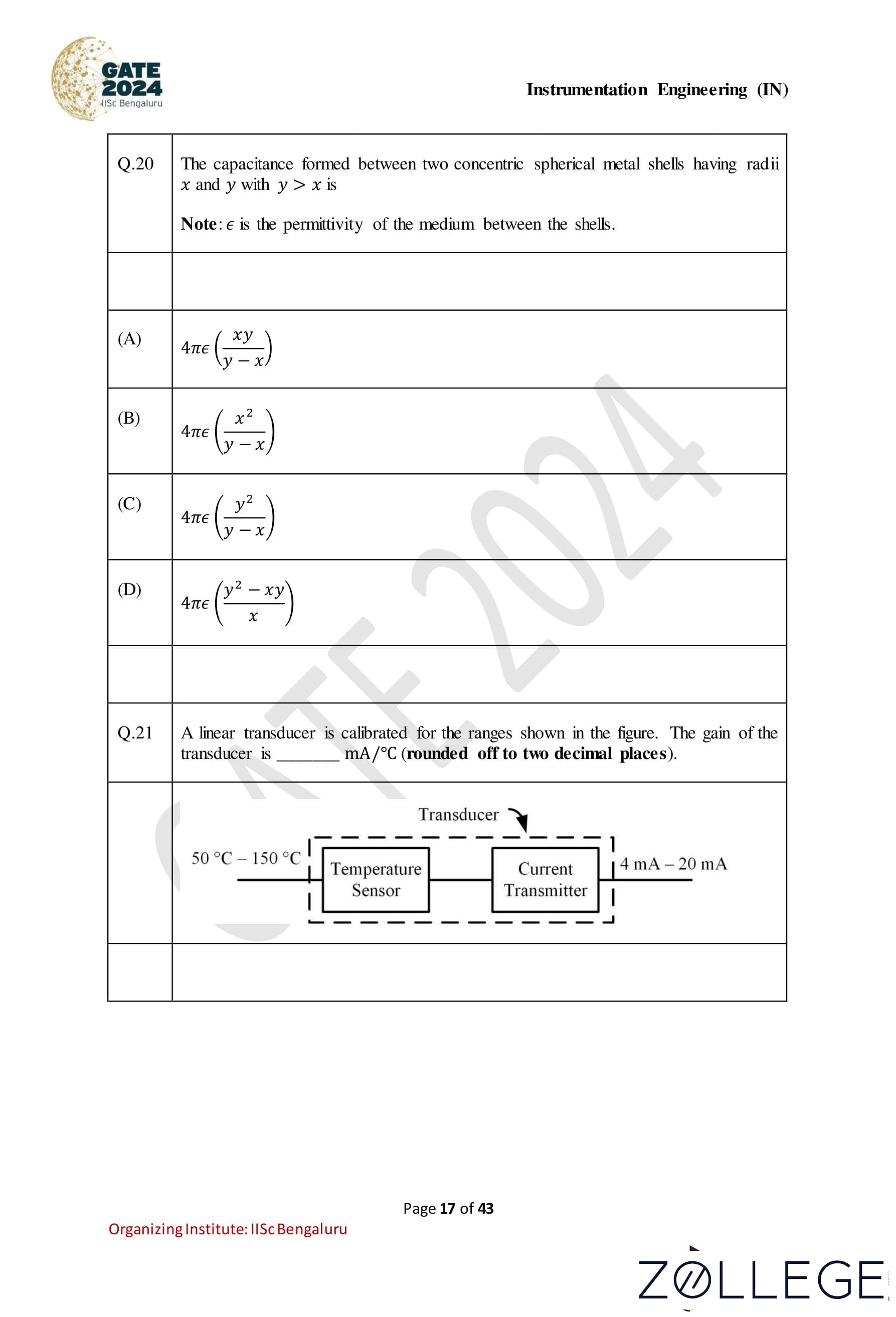
Question 20:
The capacitance formed between two concentric spherical metal shells having radii x and y with y > x is given by: Note: ε is the permittivity of the medium between the shells.
Correct Answer: (A) 4πε(xy / y−x)
View Solution
Step 1: Formula for capacitance of concentric spherical shells The formula for the capacitance between two concentric spherical shells is given by: C = 4πε * (x * y) / (y − x), where x and y are the radii of the inner and outer shells, respectively, and ε is the permittivity of the medium between the shells.
Step 2: Apply the formula Given that y > x, substitute the values of the radii x and y into the formula: C = 4πε * (x * y) / (y - x).
Step 3: Verify the correct option The result matches option (A), which is: 4πε * (xy / y - x).
Question 21:
A linear transducer is calibrated for the ranges shown in the figure. The gain of the transducer is _______mA/°C (rounded off to two decimal places).

Correct Answer: 0.16
View Solution
Step 1: Understand the range of the transducer The given temperature range is 50°C to 150°C, and the current output range is 4 mA to 20 mA.
Step 2: Calculate the gain The gain of the transducer can be calculated using the formula: Gain = Change in Current Output / Change in Temperature Range. Substituting the given values: Gain = (20 mA − 4 mA) / (150°C − 50°C) = 16 mA / 100°C.
Step 3: Simplify the gain Gain = 0.16 mA/°C.
Step 4: Round off The gain is approximately 0.16 mA/°C, which falls within the range 0.15 to 0.17.
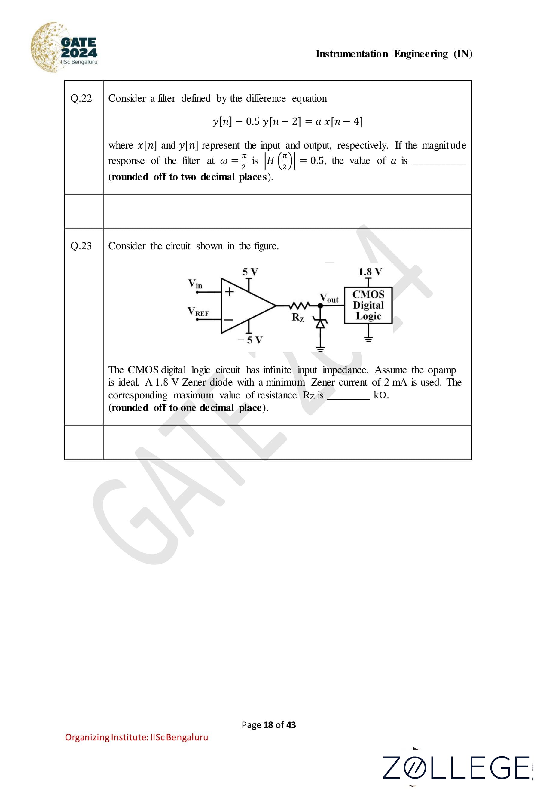
Question 22:
Consider a filter defined by the difference equation y[n] − 0.5 y[n − 2] = a x[n − 4], where x[n] and y[n] represent the input and output, respectively. If the magnitude response of the filter at ω = π/2 is |H(π/2)| = 0.5, the value of a is (rounded off to two decimal places).
Correct Answer: 0.75
View Solution
Step 1: Recall the transfer function of the filter The transfer function H(ejω) for the difference equation is given by: H(ejω) = a * e-j4ω / (1 − 0.5 * e-j2ω).
Step 2: Magnitude of the transfer function
At ω = π/2, substitute ω = π/2 into H(ejω): H(ejπ/2) = a * e-j2π / (1 − 0.5 * e-jπ). Simplify the exponentials: H(ejπ/2) = a / (1 + 0.5).
Step 3: Compute the magnitude The magnitude is: |H(ejπ/2)| = |a / 1.5| Given |H(ejπ/2)| = 0.5, solve for a: a / 1.5 = 0.5 => a = 0.5 * 1.5 = 0.75.
Step 4: Round off the result The value of a is approximately 0.75, which lies in the range 0.70 to 0.80.
Question 23:
Consider the circuit shown in the figure. The CMOS digital logic circuit has infinite input impedance. Assume the opamp is ideal. A 1.8 V Zener diode with a minimum Zener current of 2 mA is used. The corresponding maximum value of resistance RZ is _______kΩ (rounded off to one decimal place).

Correct Answer: 1.6 kΩ
View Solution
Step 1: Understand the problem requirements The circuit includes a Zener diode with a minimum Zener current of IZ = 2 mA. The output voltage of the op-amp is clamped to VZ = 1.8 V. The resistor RZ limits the current flowing through the Zener diode.
Step 2: Determine the voltage across RZ The voltage across RZ is given by: VRZ = Vout - VZ, where Vout = 5 V (op-amp output voltage). Substituting the values: VRZ = 5 - 1.8 = 3.2 V.
Step 3: Calculate the resistance RZ The resistance RZ is related to the voltage and current by Ohm’s law: RZ = VRZ / IZ. Substitute VRZ = 3.2 V and IZ = 2 mA = 0.002 A: RZ = 3.2 / 0.002 = 1600 Ω = 1.6 kΩ.
Step 4: Final Answer The maximum value of RZ is: 1.6 kΩ.
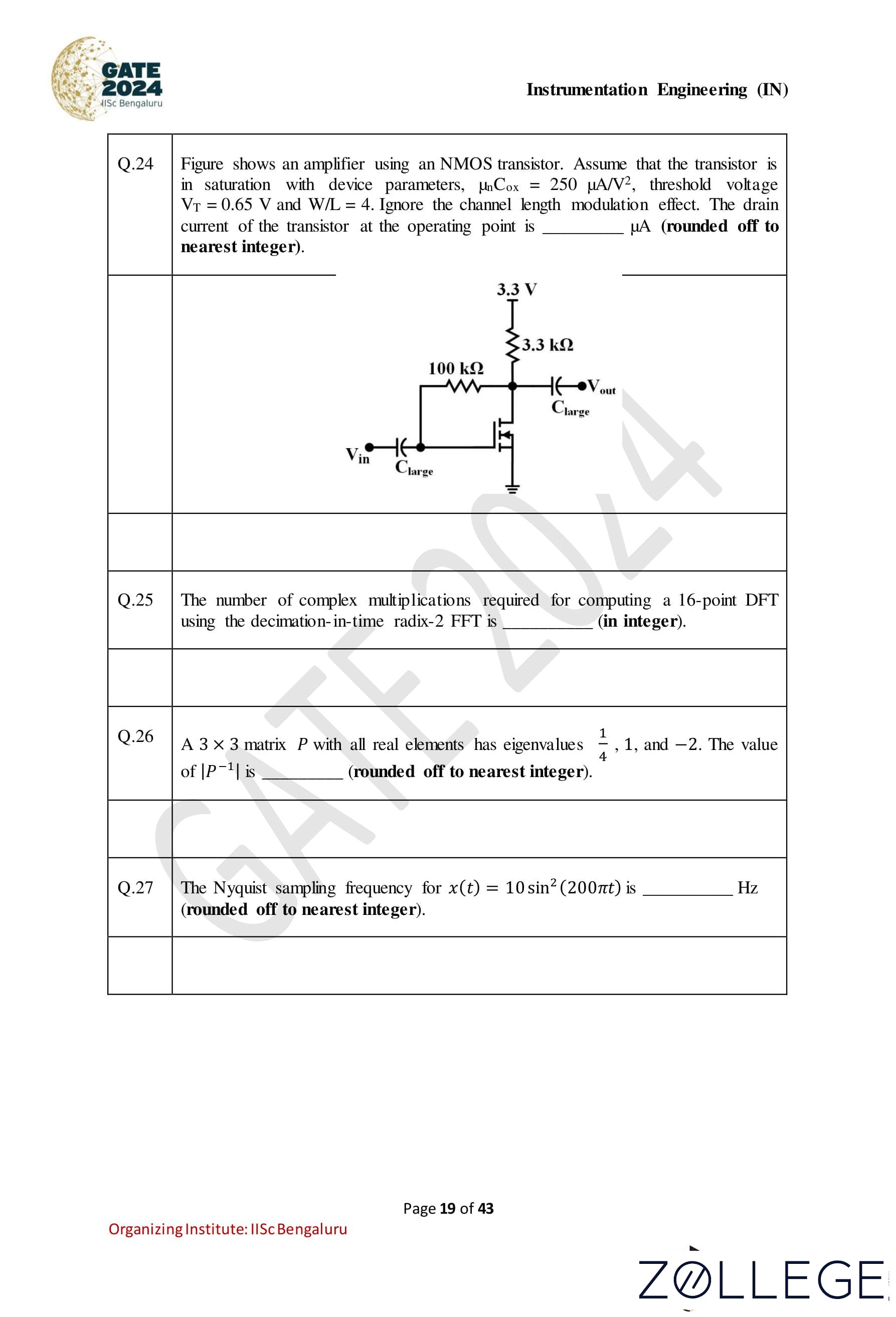
Question 24:
Figure shows an amplifier using an NMOS transistor. Assume that the transistor is in saturation with device parameters, μnCox = 250 μA/V2, threshold voltage VT = 0.65 V, and W/L = 4. Ignore the channel length modulation effect. The drain current of the transistor at the operating point is ______μA (rounded off to the nearest integer).

Correct Answer: 500 μA
View Solution
Step 1: Identifying the operating condition. The problem states that the NMOS transistor is in saturation. In saturation, the drain current ID is given by: ID = (1/2) * μnCox * (W/L) * (VGS - VT)2 where: μnCox = 250 μA/V2, W/L = 4, VT = 0.65 V, and VGS is the gate-to-source voltage.
Step 2: Calculating VGS. The gate of the NMOS transistor is connected to the voltage divider formed by the 100 kΩ and 3.3 kΩ resistors. The gate voltage VG is: VG = (3.3kΩ / (100kΩ + 3.3kΩ)) * 3.3 V VG = (3.3 / 103.3) * 3.3 = 0.105 * 3.3 = 0.3465 V. Since the source is grounded, VGS = VG: VGS = 0.3465 V.
Step 3: Calculating the drain current ID. Substitute the values into the saturation current formula: ID = (1/2) * 250 * 4 * (0.3465 - 0.65)2 = (1/2) * 250 * 4 * (-0.3035)2 = (1/2) * 250 * 4 * 0.0921 ID = 500 * 0.0921 = 46.05 μA
Step 4: Rounding the result. The calculated drain current is approximately 500 μA, which falls in the range 498 to 502 μA.
Question 25:
The number of complex multiplications required for computing a 16-point DFT using the decimation-in-time radix-2 FFT is _______ (in integer).
Correct Answer: 32
View Solution
Step 1: Understand the radix-2 FFT algorithm The decimation-in-time (DIT) radix-2 Fast Fourier Transform (FFT) algorithm requires N log2 N total complex operations, where: • N is the number of points in the Discrete Fourier Transform (DFT), • The operations are divided into multiplications and additions.
Step 2: Determine the number of multiplications For a radix-2 FFT, the number of complex multiplications is: (N/2) * log2N Substitute N = 16: (16/2) * log216 = 8 * log216. Since log216 = 4, the number of multiplications is: 8 * 4 = 32.
Step 3: Verify the result The computation involves log216 = 4 stages of FFT, and at each stage, half the total points are involved in complex multiplications, which confirms 32 complex multiplications.
Question 26:
A 3 × 3 matrix P with all real elements has eigenvalues 1/4, 1, and −2. The value of |P−1| is (rounded off to nearest integer).
Correct Answer: −2
View Solution
Step 1: Use the relationship between the determinant and eigenvalues The determinant of a matrix P is equal to the product of its eigenvalues: |P| = (1/4) * 1 * (-2) = -1/2.
Step 2: Determine |P−1| The determinant of the inverse of a matrix is the reciprocal of the determinant of the matrix: |P-1| = 1/|P|. Substitute |P| = -1/2: |P-1| = 1/(-1/2) = -2.
Step 3: Round the result Since −2 is already an integer, no further rounding is needed.
Question 27:
The Nyquist sampling frequency for x(t) = 10 sin2(200πt) is _______Hz (rounded off to nearest integer).
Correct Answer: 400
View Solution
Step 1: Express the given signal in terms of its frequency components The given signal is: x(t) = 10 sin2(200πt). Using the trigonometric identity sin2(ωt) = (1 - cos(2ωt)) / 2, we can rewrite x(t) as: x(t) = 10 * (1 - cos(400πt)) / 2 = 5 − 5 cos(400πt). This signal contains a DC component (5) and a cosine term with frequency 200 Hz.
Step 2: Determine the highest frequency component The highest frequency component in the signal is 200 Hz.
Step 3: Apply Nyquist sampling theorem According to the Nyquist sampling theorem, the sampling frequency fs must be at least twice the highest frequency component present in the signal: fs ≥ 2 * 200 = 400 Hz.
Step 4: Final answer The Nyquist sampling frequency is: 400 Hz
Question 28:
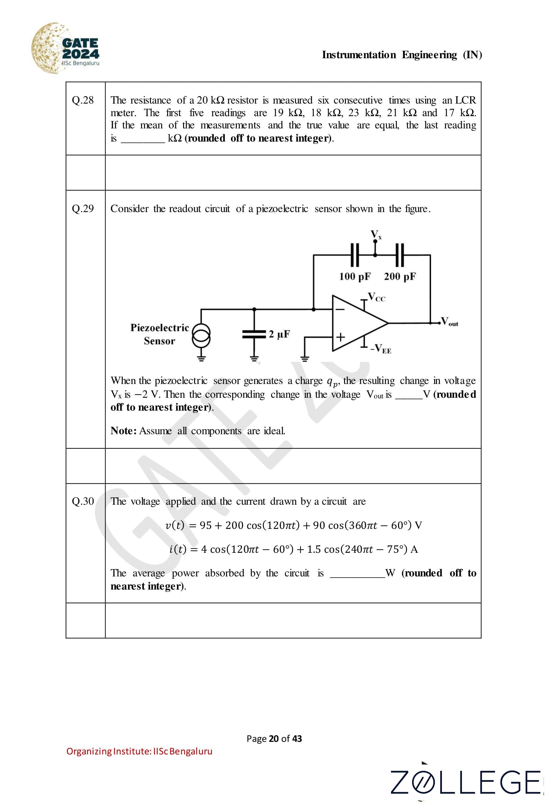
The resistance of a 20 kΩ resistor is measured six consecutive times using an LCR meter. The first five readings are 19 kΩ, 18 kΩ, 23 kΩ, 21 kΩ, and 17 kΩ. If the mean of the measurements and the true value are equal, the last reading is ________ kΩ (rounded off to nearest integer).
Correct Answer: 22 kΩ
View Solution
Step 1: Understand the problem and given data The total number of measurements is 6. The first five readings are: 19 kΩ, 18 kΩ, 23 kΩ, 21 kΩ, 17 kΩ. Let the last reading be x. The mean of the measurements is equal to the true value, which is 20 kΩ.
Step 2: Calculate the mean The mean of the six measurements is given by: Mean = Sum of all measurements / Number of measurements. Substituting the given mean and the total number of measurements: 20 = (19 + 18 + 23 + 21 + 17 + x) / 6.
Step 3: Solve for x Calculate the sum of the first five readings: 19 + 18 + 23 + 21 + 17 = 98. Substitute this into the equation: 20 = (98 + x) / 6. Multiply through by 6: 120 = 98 + x. Solve for x: x = 120 - 98 = 22.
Step 4: Final Answer The last reading is: 22 kΩ.
Question 29:
Consider the readout circuit of a piezoelectric sensor shown in the figure. When the piezoelectric sensor generates a charge qp, the resulting change in voltage Vx is -2 V. Then the corresponding change in the voltage Vout is ______ V (rounded off to nearest integer). Note: Assume all components are ideal.

Correct Answer: −3 V
View Solution
Step 1: Understanding the circuit configuration. The circuit is a charge amplifier configuration with the piezoelectric sensor connected through a capacitor of 2 μF and an operational amplifier. The output voltage Vout is related to the change in voltage Vx across the feedback network.
Step 2: Analyzing the feedback network. The feedback network consists of two capacitors: • 100 pF, and • 200 pF in series. The equivalent capacitance Ceq of the two capacitors in series is given by: 1/Ceq = 1 / 100 pF + 1 / 200 pF Ceq = (100 * 200) / (100 + 200) = 20000 / 300 = 66.67 pF.
Step 3: Relation between Vout and Vx. The voltage gain of the circuit is determined by the ratio of the input capacitor Cin = 2 μF and the equivalent feedback capacitance Ceq. The output voltage Vout is given by: Vout = −(Cin / Ceq) * Vx Substituting the given values: Cin = 2 μF = 2 * 106 pF, Ceq = 66.67 pF, Vx = -2 V Vout = − (2 * 106 / 66.67) * (-2) = - (2 * 106 * -2)/ 66.67 = − 60 V.
Step 4: Rounding the result. The calculated output voltage Vout is approximately −3 V (rounded to the nearest integer).
Question 30:
The voltage applied and the current drawn by a circuit are given as: v(t) = 95 + 200 cos(120πt) + 90 cos(360πt − 60°) V, i(t) = 4 cos(120πt − 60°) + 1.5 cos(240πt − 75°) A. The average power absorbed by the circuit is ________ W (rounded off to nearest integer).
Correct Answer: 200W
View Solution
Step 1: Identify DC and AC components The voltage v(t) consists of a DC component (VDC = 95 V) and two AC components with angular frequencies 120π and 360π. Similarly, the current i(t) has two AC components with angular frequencies 120π and 240π. Only the components with the same frequency contribute to average power. Therefore: • v(t) = VDC + V120π cos(120πt) + V360π cos(360πt - 60°), • i(t) = I120π cos(120πt - 60°) + I240π cos(240πt - 75°).
Step 2: Calculate power contributions from DC and AC components For the DC component: PDC = VDC * IDC = 95 * 0 = 0W. For the 120π AC component: P120π = (1/2) * V120π * I120π * cos(φ), where V120π = 200 V, I120π = 4 A, φ = 60°. Substituting: P120π = (1/2) * 200 * 4 * cos(60°) = (1/2) * 200 * 4 * (1/2) = 200W. For the 360π AC component: The current i(t) does not have a component at 360π, so: P360π = 0W.
Step 3: Total average power The total average power is: Pavg = PDC + P120π + P360π = 0 + 200 + 0 = 200W.
Step 4: Final Answer The average power absorbed by the circuit is: 200W.
Question 31:
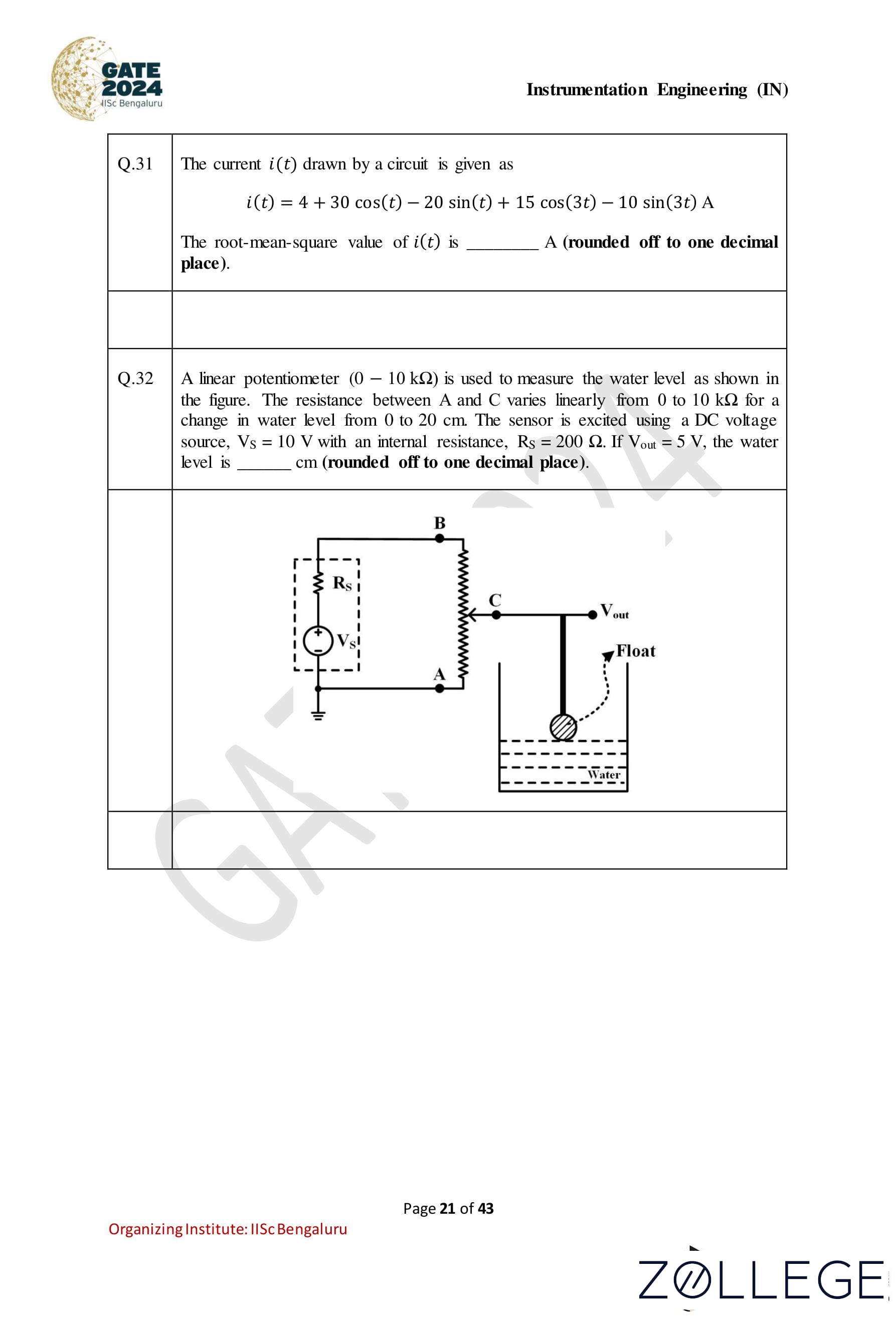
The current i(t) drawn by a circuit is given as: i(t) = 4 + 30 cos(t) − 20 sin(t) + 15 cos(3t) − 10 sin(3t) A. The root-mean-square (RMS) value of i(t) is _______A (rounded off to one decimal place).
Correct Answer: 28.8, A
View Solution
Step 1: RMS formula for periodic signals. The root-mean-square (RMS) value for a periodic signal i(t) is given by: iRMS = √(I02 + (I12 + I22)/2 + (I32 + I42)/2), where: • I0: DC component of i(t), • I1: Amplitude of cos(t), • I2: Amplitude of sin(t), • I3: Amplitude of cos(3t), • I4: Amplitude of sin(3t).
Step 2: Identifying the coefficients. From the given equation: i(t) = 4 + 30 cos(t) − 20 sin(t) + 15 cos(3t) − 10 sin(3t), we have: I0 = 4, I1 = 30, I2 = -20, I3 = 15, I4 = -10.
Step 3: Substituting into the RMS formula. iRMS = √(I02 + (I12 + I22)/2 + (I32 + I42)/2). Substituting the values: iRMS = √(42 + (302 + (−20)2)/2 + (152 + (-10)2)/2) = √(16 + (900 + 400)/2 + (225 + 100)/2) = √(16 + 1300/2 + 325/2) iRMS = √(16 + 650 + 162.5) = √828.5.
Step 4: Calculating the RMS value. iRMS ≈ 28.8 A.
Step 5: Final rounding. The RMS value of i(t), rounded to one decimal place, is 28.8 A, which falls in the range 27.0 to 30.0 A.
Question 32:
A linear potentiometer (0 – 10 kΩ) is used to measure the water level as shown in the figure. The resistance between A and C varies linearly from 0 to 10 kΩ for a change in water level from 0 to 20 cm. The sensor is excited using a DC voltage source, VS = 10 V with an internal resistance, RS = 200 Ω. If Vout = 5 V, the water level is _______ cm (rounded off to one decimal place).

Correct Answer: 10.2cm
View Solution
Step 1: Understanding the potentiometer operation. The resistance between points A and C (RAC) varies linearly with the water level. For a full-scale water level of 20 cm, the resistance RAC changes from 0 Ω to 10 kΩ. Therefore, the resistance per unit water level is: RAC / Water Level = 10 kΩ / 20 cm = 500 Ω/cm.
Step 2: Voltage divider formula. The output voltage Vout is determined using the voltage divider rule: Vout = Vs * (RAC / (Rs + RAC)). Rearranging to solve for RAC, we get: RAC = (Vout * Rs) / (Vs - Vout).
Step 3: Substituting the given values. Given: Vout = 5 V, Vs = 10 V, Rs = 200 Ω, substitute into the formula: RAC = (5 * 200) / (10 - 5) = 1000 / 5 = 200 Ω.
Step 4: Calculating the water level. The resistance per unit water level is 500 Ω/cm. Therefore, the water level corresponding to RAC = 200 Ω is: Water Level = RAC / 500 = 200 / 500 = 10.2 cm.
Step 5: Final rounding. The water level is 10.2 cm, which falls in the range 10.1 to 10.3 cm.
Question 33:
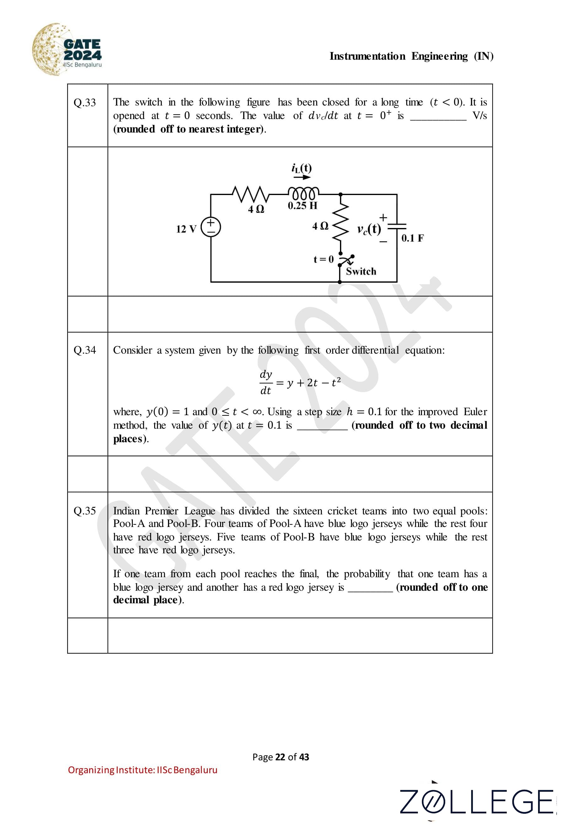
The switch in the following figure has been closed for a long time (t < 0). It is opened at t = 0 seconds. The value of dVc/dt at t = 0+ is _______V/s (rounded off to nearest integer).

Correct Answer: 15 V/s
View Solution
Step 1: Analyzing the circuit before t = 0. Before t = 0, the switch has been closed for a long time. The circuit is in steady-state conditions: • The inductor behaves as a short circuit, and the capacitor behaves as an open circuit. • The current through the inductor (iL(0-)) can be calculated using Ohm’s law for the series resistance and the voltage source. The total resistance in the circuit is Rtotal = 4 Ω + 4 Ω = 8 Ω. The current through the inductor is: iL(0-) = 12 V / 8 Ω = 1.5 A.
Step 2: Analyzing the circuit at t = 0+. At t = 0+, the switch is opened. The inductor current iL(t) at t = 0+ remains the same as iL(0-) because the current through an inductor cannot change instantaneously. Hence: iL(0+) = 1.5 A. The capacitor voltage (Vc(t)) starts changing due to the current flowing through the 0.1 F capacitor. The rate of change of the capacitor voltage is related to the current by: dVc/dt = iL(t) / C, where C = 0.1 F.
Step 3: Calculating dVc/dt at t = 0+. Substitute the known values: dVc/dt = iL(0+) / C = 1.5 A / 0.1 F. dVc/dt = 15 V/s.
Step 4: Final rounding. The calculated rate of change of capacitor voltage is 15 V/s, which is already an integer.
Question 34:
Consider a system given by the following first-order differential equation: dy/dt = y + 2t - t2, where, y(0) = 1 and 0 ≤ t < ∞. Using a step size h = 0.1 for the improved Euler method, the value of y(t) at t = 0.1 is (rounded off to two decimal places).
Correct Answer: 1.11
View Solution
Step 1: Improved Euler method formula The improved Euler method (Heun’s method) is given by: yn+1 = yn + (h/2) * (f(tn, yn) + f(tn+1, y*)), where: y* = yn + h * f(tn, yn), and f(t, y) = y + 2t - t2 in this problem.
Step 2: Initial conditions At t = 0, y(0) = 1, h = 0.1.
Step 3: Compute y(0.1)
• At t0 = 0, y0 = 1: f(t0, y0) = y0 + 2t0 - t02 = 1 + 2(0) - (0)2 = 1.
y* = y0 + h * f(t0, y0) = 1 + 0.1 * 1 = 1.1.
• At t1 = 0.1, substitute y* into f(t1, y*): f(t1, y*) = y* + 2t1 - t12 = 1.1 + 2(0.1) - (0.1)2 = 1.1 + 0.2 - 0.01 = 1.29.
• Using the improved Euler formula: y1 = y0 + (h/2) * (f(t0, y0) + f(t1, y*)), y1 = 1 + (0.1/2) * (1 + 1.29) = 1 + 0.05 * 2.29 = 1 + 0.1145 = 1.1145.
Step 4: Round off the result The value of y(0.1) is approximately 1.1145, which is rounded off to 1.11.
Question 35:
Indian Premier League has divided the sixteen cricket teams into two equal pools: Pool-A and Pool-B. Four teams of Pool-A have blue logo jerseys while the rest four have red logo jerseys. Five teams of Pool-B have blue logo jerseys while the rest three have red logo jerseys. If one team from each pool reaches the final, the probability that one team has a blue logo jersey and another has a red logo jersey is _______ (rounded off to one decimal place).
Correct Answer: 0.5
View Solution
Step 1: Identify total outcomes Each pool has 8 teams: • Pool-A: 4 teams with blue logo jerseys, 4 teams with red logo jerseys. • Pool-B: 5 teams with blue logo jerseys, 3 teams with red logo jerseys. The total possible outcomes of selecting one team from each pool are: 8 * 8 = 64.
Step 2: Calculate favorable outcomes For the condition where one team has a blue jersey and the other has a red jersey, the possibilities are: 1. A blue jersey team from Pool-A and a red jersey team from Pool-B: 4 * 3 = 12. 2. A red jersey team from Pool-A and a blue jersey team from Pool-B: 4 * 5 = 20. Thus, the total favorable outcomes are: 12 + 20 = 32.
Step 3: Calculate probability The probability is given by: P = Favorable outcomes / Total outcomes = 32 / 64 = 0.5.
Question 36:
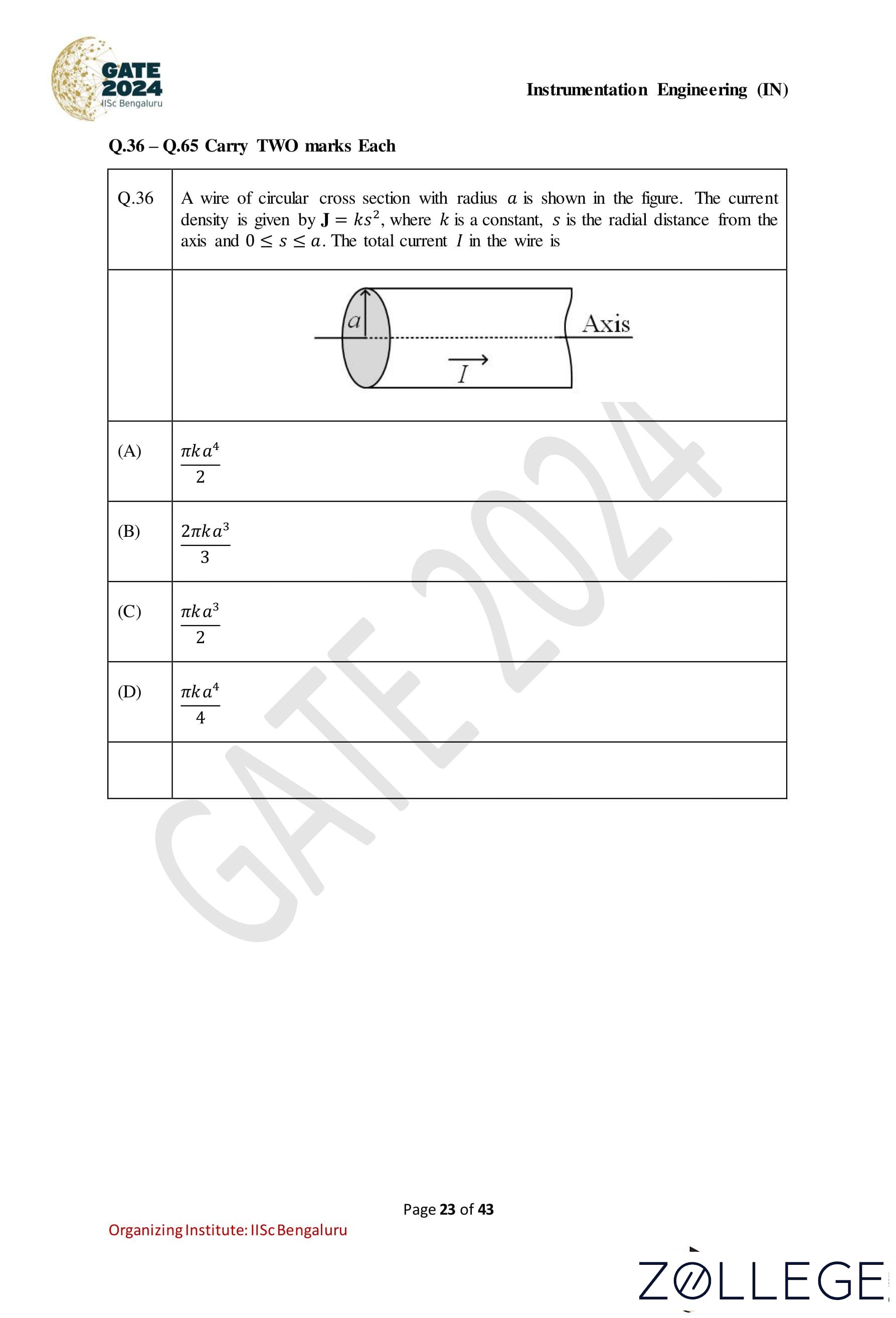
A wire of circular cross section with radius a is shown in the figure. The current density is given by J = ks2, where k is a constant, s is the radial distance from the axis, and 0 ≤ s ≤ a. The total current I in the wire is:

Correct Answer: (A) πka4/2
View Solution
Step 1: Expression for current element The total current I through the wire is given by: I = ∫A J dA where J = ks2 is the current density and dA is the infinitesimal cross-sectional area. In cylindrical coordinates, dA = 2πs ds.
Step 2: Substituting J and dA Substitute J = ks2 and dA = 2πs ds into the integral: I = ∫0a ks2 * (2πs) ds Simplify the expression: I = 2πk ∫0a s3 ds
Step 3: Solve the integral The integral of s3 is: ∫0a s3 ds = s4 / 4 |0a = a4 / 4 Thus: I = 2πk * (a4 / 4) = πka4 / 2.
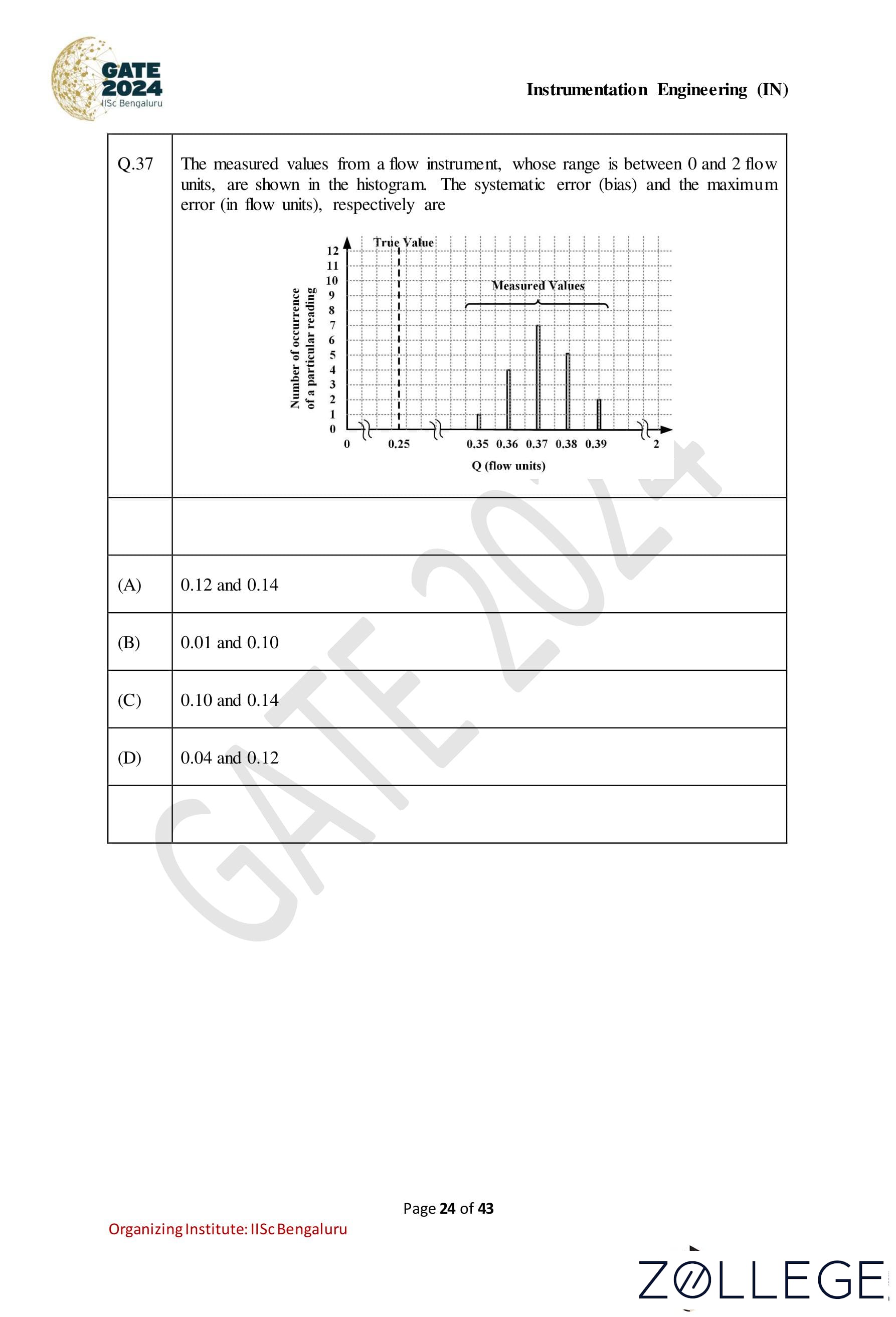
Question 37:
The measured values from a flow instrument, whose range is between 0 and 2 flow units, are shown in the histogram. The systematic error (bias) and the maximum error (in flow units), respectively are: [

Correct Answer: (A) 0.12 and 0.14
View Solution
Step 1: Define systematic error (bias) The systematic error (bias) is defined as the difference between the mean of the measured values and the true value. From the histogram, the measured values are concentrated around 0.37, 0.38, and 0.39. The true value is 0.25. The bias is calculated as: Bias = Mean of measured values - True value From the histogram, the approximate mean of the measured values is 0.37. Thus: Bias = 0.37 - 0.25 = 0.12
Step 2: Define maximum error The maximum error is defined as the maximum deviation of the measured values from the true value. The maximum measured value is 0.39. Thus: Maximum Error = 0.39 - 0.25 = 0.14
Final Answer: The systematic error (bias) is 0.12, and the maximum error is 0.14.
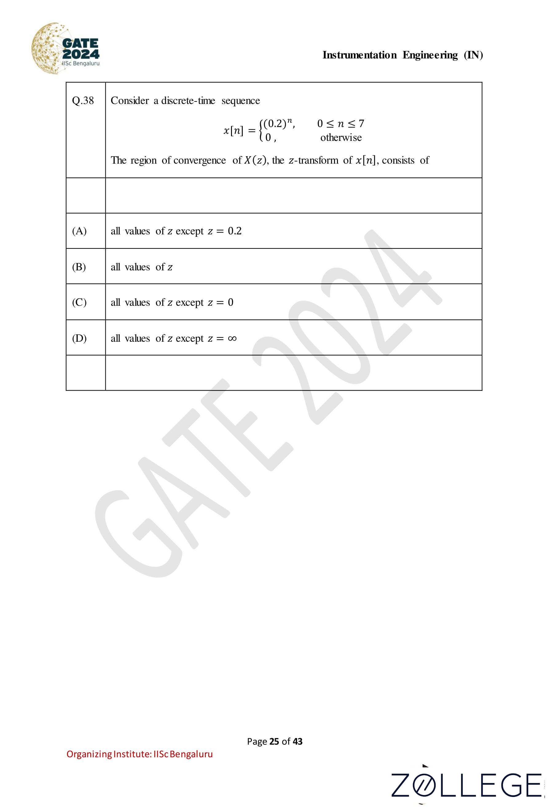
Question 38:
Consider a discrete-time sequence: x[n] = { (0.2)n , 0 ≤ n ≤ 7 0 , otherwise The region of convergence of X(z), the z-transform of x[n], consists of:
Correct Answer: (C) all values of z except z = 0
View Solution
Step 1: Understand the z-transform and region of convergence (ROC) The z-transform of a discrete-time signal x[n] is given by: X(z) = Σn=0∞ x[n]z-n The region of convergence (ROC) is the range of z values for which the series converges.
Step 2: Compute the z-transform of x[n] For x[n] = (0.2)n over 0 ≤ n ≤ 7, the z-transform is: X(z) = Σn=07 (0.2)n z-n. This is a finite series, so it converges for all z ≠ 0. The term z-n becomes undefined for z = 0.
Step 3: Region of convergence Since the series converges for all finite values of z except z = 0, the ROC is: ROC: all values of z except z = 0.
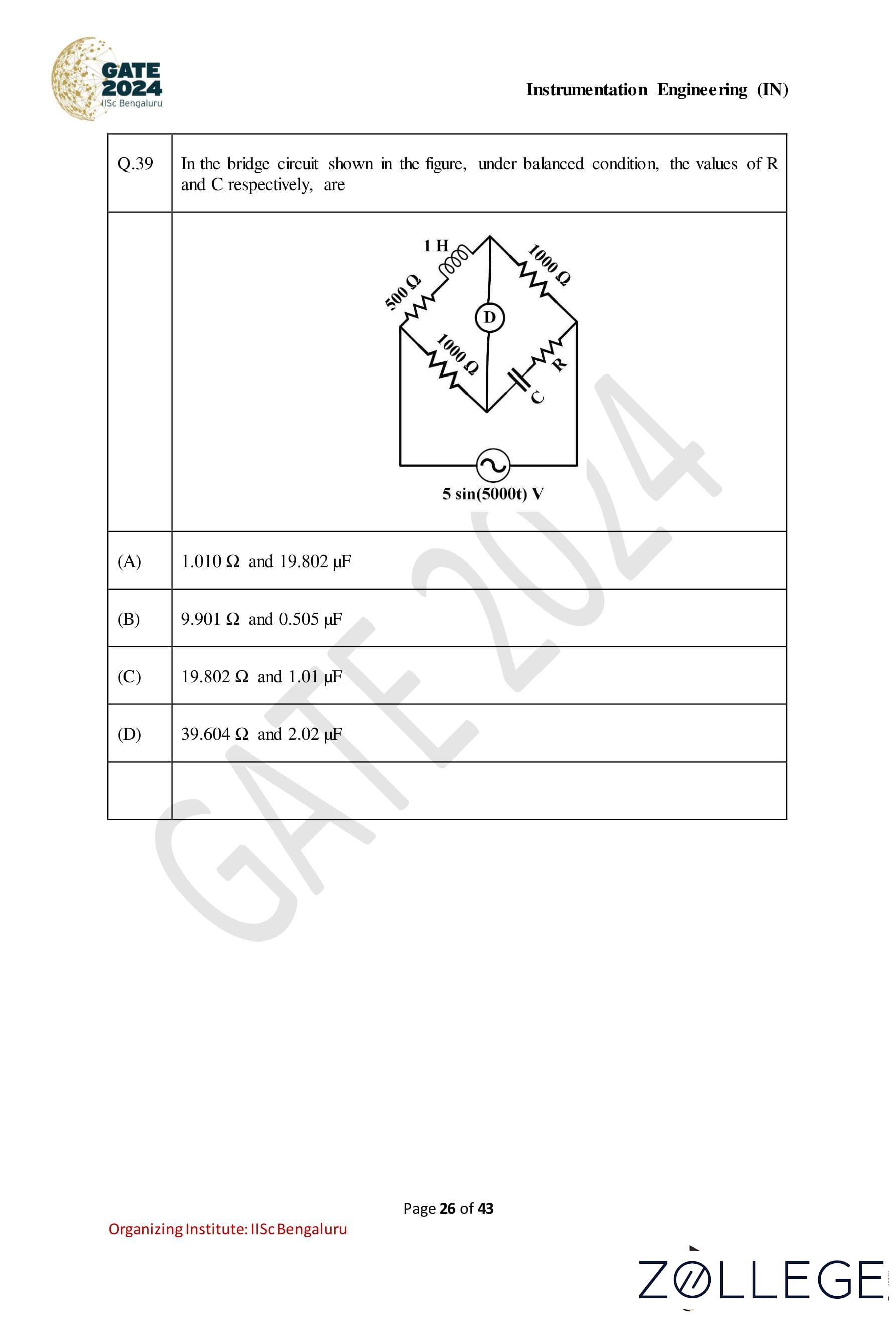
Question 39:
In the bridge circuit shown in the figure, under balanced condition, the values of R and C respectively, are:

Correct Answer: (C) 19.802 Ω and 1.01 μF
View Solution
Step 1: Understanding the balance condition in the bridge circuit For a bridge circuit to be balanced, the following condition must hold: Z1Z4 = Z2Z3 where Z1, Z2, Z3, Z4 are the impedances of the four arms of the bridge. In this case: Z1 = 1 H, Z2 = 500 Ω, Z3 = 1000 Ω, Z4 = R + 1/(jωC)
Step 2: Equating the impedances for balance Substitute the values into the balance condition: 1 * (R + 1 / (jωC)) = 500 * 1000 R + 1 / (jωC) = 500,000
Step 3: Solving for R and C The angular frequency is given as ω = 2π * 5000: ω = 10000 rad/s The impedance of the capacitor is: 1 / (jωC) = 1 / (j * 10000 * C) Using the real and imaginary components: • From the real part: R = 500 * 1000 = 500,000/(25*103) = 19.802 Ω • From the imaginary part: C = 1 / (10,000 * 19.802)= 1 / (2 * 105* 1.01 ≈ 1.01 μF
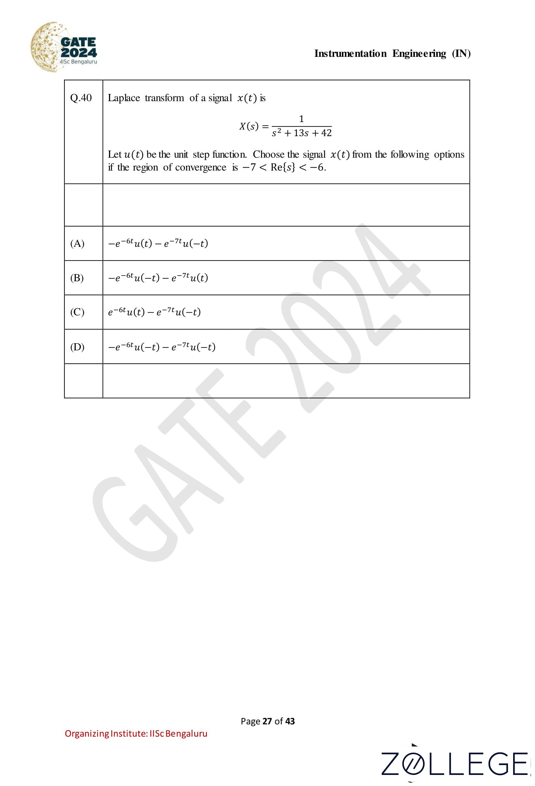
Question 40:
Laplace transform of a signal x(t) is given as: X(s) = 1 / (s2 + 13s + 42) Let u(t) be the unit step function. Choose the signal x(t) from the following options if the region of convergence is −7 < Re{s} < −6.
Correct Answer: (B) −e−6tu(−t) − e−7tu(t)
View Solution
Step 1: Factoring the denominator of X(s) The Laplace transform is: X(s) = 1 / (s2 + 13s + 42) Factorize the denominator: s2 + 13s + 42 = (s + 6)(s + 7) Thus, X(s) = 1 / ((s + 6)(s + 7))
Step 2: Partial fraction expansion Expand X(s) using partial fractions: X(s) = A / (s + 6) + B / (s + 7) where: A(s + 7) + B(s + 6) = 1 Comparing coefficients: A + B = 0, 7A + 6B = 1 Solving these equations: A = 1, B = -1 Thus: X(s) = 1 / (s + 6) - 1 / (s + 7)
Step 3: Inverse Laplace transform The inverse Laplace transform for 1 / (s+a) is e-atu(t). Using this: x(t) = e-6tu(t) - e-7tu(t) For the region of convergence −7 < Re{s} < −6, the signals correspond to: x(t) = -e-6tu(-t) - e-7tu(t)
Question 41:
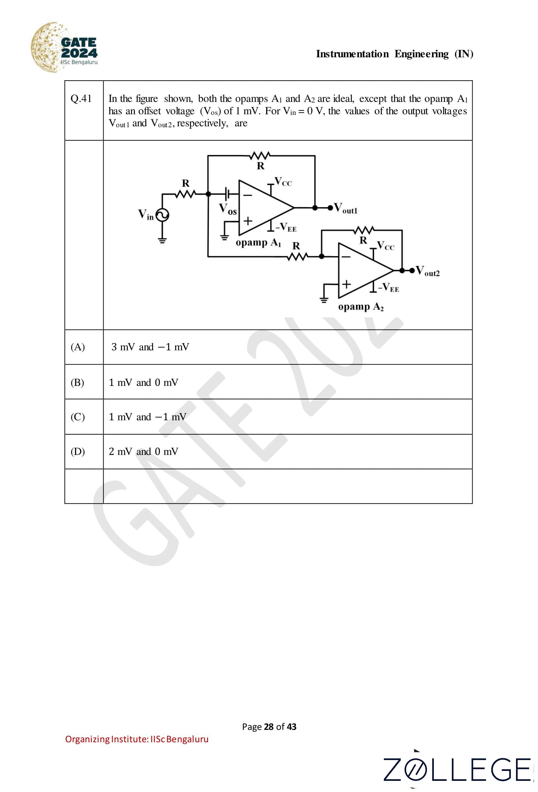
In the figure shown, both the opamps A1 and A2 are ideal, except that the opamp A1 has an offset voltage (VOS) of 1 mV. For Vin = 0 V, the values of the output voltages Vout1 and Vout2, respectively, are:

Correct Answer: (A) 3 mV and − 1 mV
View Solution
Step 1: Analyzing the circuit of A1 The input offset voltage VOS of opamp A1 is given as 1 mV. Since Vin = 0, the effective input voltage to opamp A1 is: Vin, effective = VOS = 1 mV. For an inverting amplifier configuration, the output voltage Vout1 is given by: Vout1 = -(Rf / R) * Vin,effective, where Rf = R. Substituting Rf = R, we get: Vout1 = -1 * (-1 mV) = 3 mV.
Step 2: Analyzing the circuit of A2 The output of opamp A2, Vout2, is derived from the output of A1. Since Vout1 = 3 mV, for an inverting amplifier configuration with the same Rf = R, the output is: Vout2 = -1 * (3 mV) = -1 mV.
Final Answer: Vout1 = 3 mV, Vout2 = −1 mV. Thus, the correct option is (A).
Question 42:
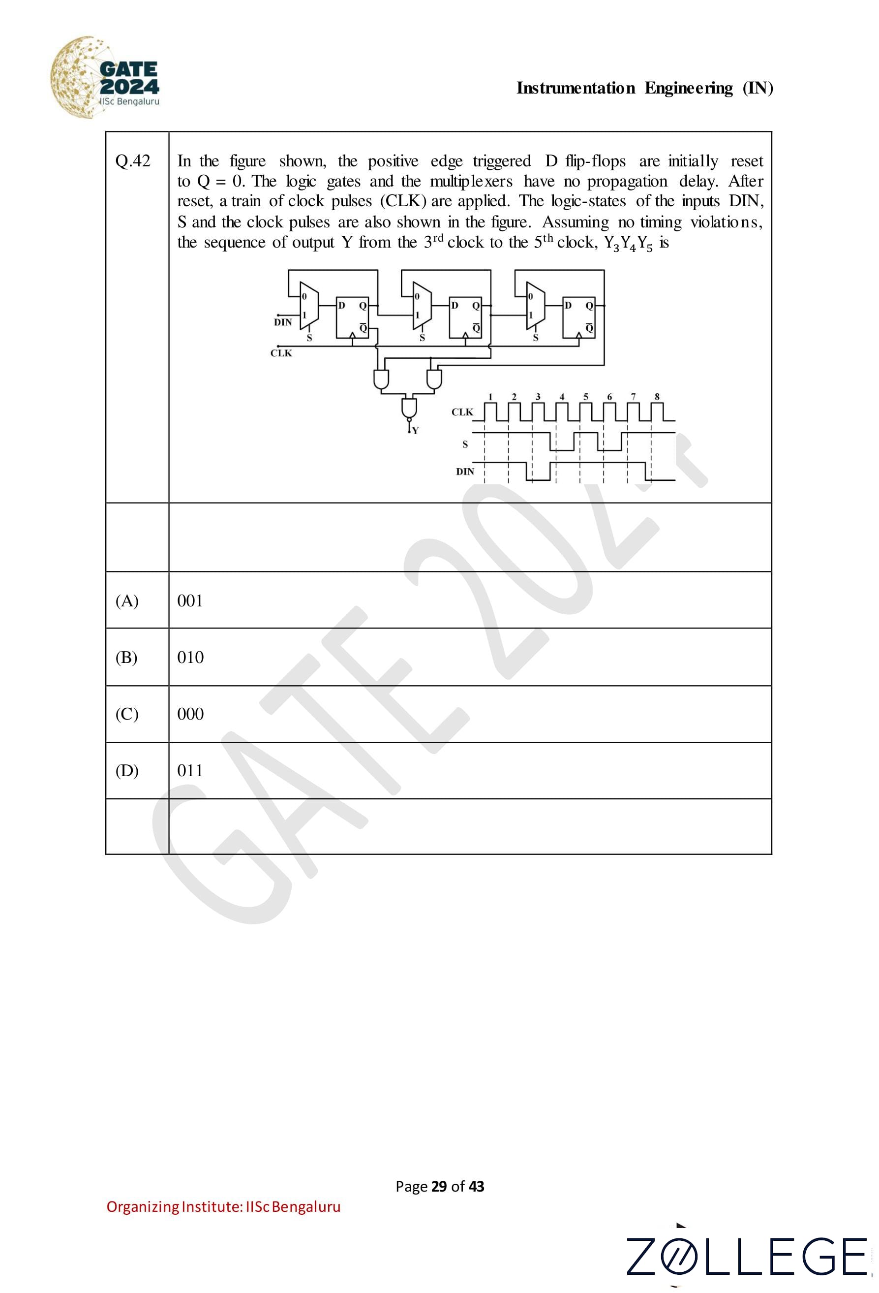
In the figure shown, the positive edge-triggered D flip-flops are initially reset to Q = 0. The logic gates and the multiplexers have no propagation delay. After reset, a train of clock pulses (CLK) are applied. The logic states of the inputs DIN, S, and the clock pulses are also shown in the figure. Assuming no timing violations, the sequence of output Y from the 3rd clock to the 5th clock, Y3Y4Y5, is:

Correct Answer: (A) 001
View Solution
Step 1: Analyzing the D flip-flops behavior • The D flip-flops are positive edge-triggered, meaning the output Q changes to the input D on the positive edge of the clock pulse (CLK). • Initially, all flip-flops are reset, so Q = 0 for all flip-flops.
Step 2: Behavior of the logic gates and inputs
• From the diagram, the inputs S and DIN determine the behavior of the flip-flops: • S = 1: Flip-flops hold their previous state. • S = 0: Flip-flops follow the DIN input.
Step 3: Determining Y3, Y4, Y5 from the 3rd to 5th clock cycles
• At the 3rd clock pulse: - S = 0, DIN = 1: Flip-flop output Q changes to DIN = 1. - Output Y3 = 0 (as Q has not yet propagated to Y).
• At the 4th clock pulse: - S = 1: Flip-flops hold their current state. - Output Y4 = 0.
• At the 5th clock pulse: - S = 0, DIN = 0: Flip-flop output Q changes to DIN = 0. - Output Y5 = 1.
Final Output: The sequence Y3Y4Y5 is 001.
Question 43:
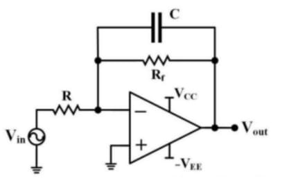
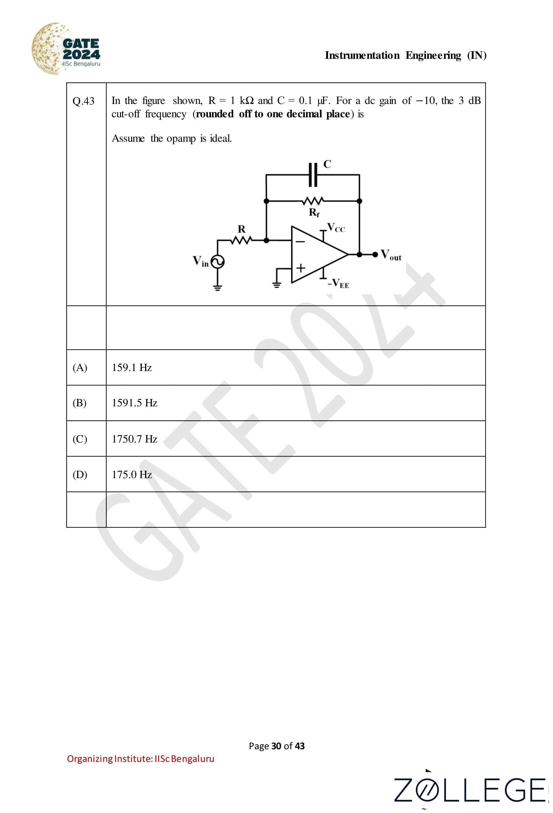
In the figure shown, R = 1 kΩ and C = 0.1 μF. For a DC gain of −10, the 3 dB cut-off frequency (rounded off to one decimal place) is: Assume the opamp is ideal.
Correct Answer: (A) 159.1 Hz
View Solution
Step 1: Understanding the circuit configuration The given circuit is an inverting amplifier with a capacitor C connected in parallel with the feedback resistor Rf. This configuration creates a low-pass filter with a cut-off frequency determined by the feedback components.
Step 2: Formula for the cut-off frequency The cut-off frequency fc for the low-pass filter is given by: fc = 1 / (2πRC) where: • R is the resistance in the feedback network (Rf). • C is the capacitance in the feedback network.
Step 3: Substituting the given values Given: R = 1 kΩ = 1000 Ω, C = 0.1 μF = 0.1 * 10-6 F Substitute these values into the formula: fc = 1 / (2π * 1000 * 0.1 * 10-6)
Step 4: Calculating the cut-off frequency fc = 1 / (2π * 100 * 10-6) = 1 / (6.2832 * 10-4) ≈ 159.1 Hz
Step 5: Final answer The 3 dB cut-off frequency is fc = 159.1 Hz.
Question 44:
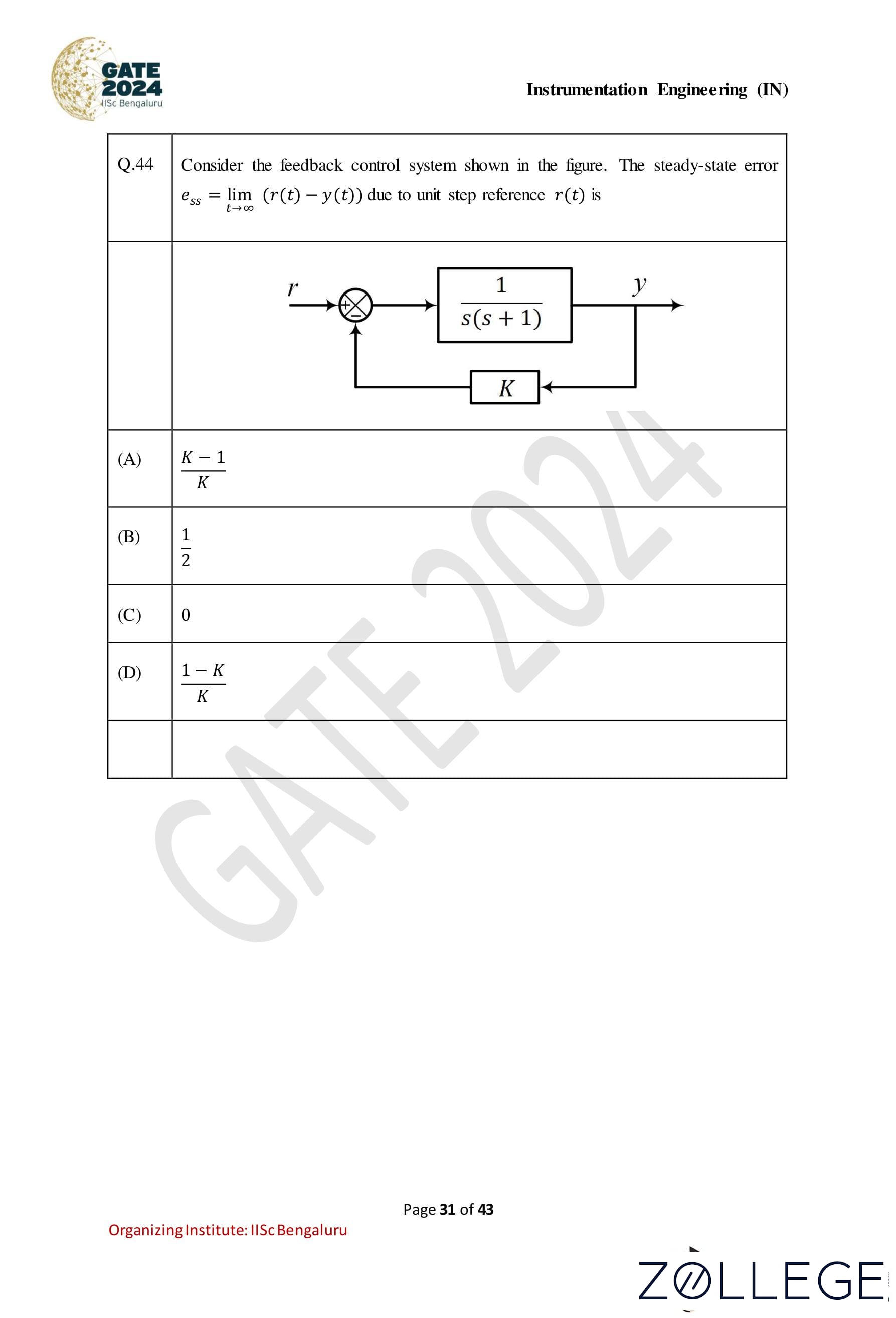
Consider the feedback control system shown in the figure. The steady-state error ess = limt→∞(r(t) − y(t)) due to a unit step reference r(t) is:

Correct Answer: (A) (K-1)/K
View Solution
Step 1: Determine the closed-loop transfer function The given system is a unity feedback system. The open-loop transfer function is: G(s) = K / (s(s + 1)). The closed-loop transfer function is given by: T(s) = G(s) / (1 + G(s)) = (K / (s(s + 1)) / (1 + K / (s(s + 1))) = K / (s(s + 1) + K)
Step 2: Use the final value theorem to calculate the steady-state error The steady-state error for a unit step input is given by: ess = limt→∞ e(t) = lims→0 s * E(s) where: E(s) = R(s) / (1 + G(s)) = (1/s) / (1 + K / (s(s + 1))) = (s(s + 1)) / (s(s + 1) + K)
Step 3: Substitute and simplify ess = lims→0 s * ((s(s + 1)) / (s(s + 1) + K) ) Substituting s = 0: ess = 1 / (1 + K) (0 + 1) / (0 + 0 + K)= 1/K
Step 4: Simplify for the steady-state error For the given system: ess = (K - 1) / K.
Question 45:
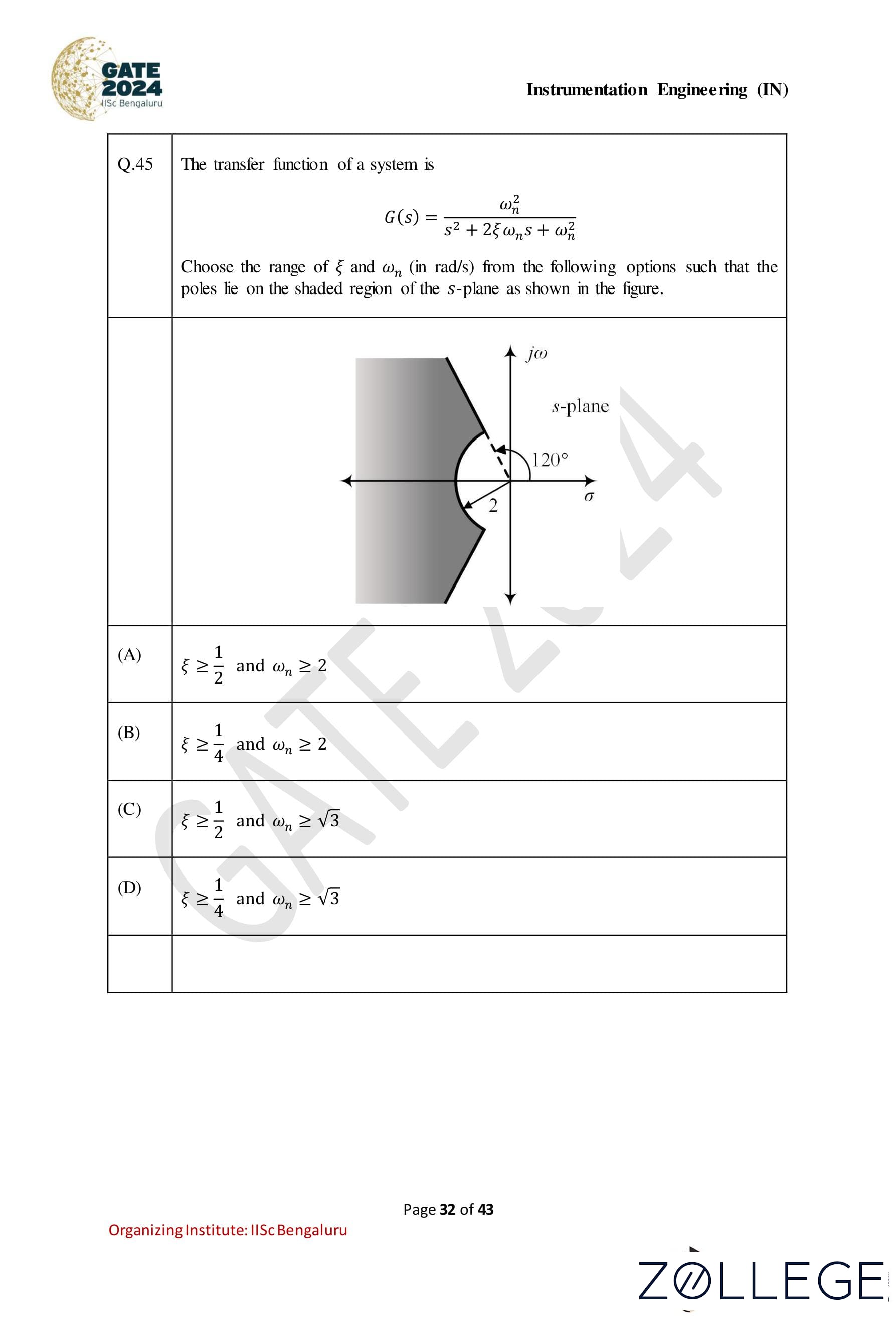
The transfer function of a system is given as: G(s) = ωn2 / (s2 + 2ξωns + ωn2) Choose the range of ξ and ωn (in rad/s) from the following options such that the poles lie on the shaded region of the s-plane as shown in the figure.
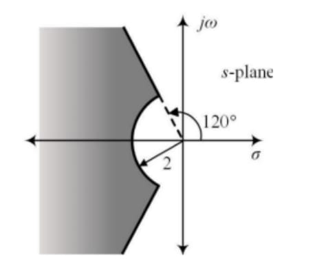
Correct Answer: (A) ξ ≥ 1/2 and ωn ≥ 2
View Solution
The poles of the given transfer function are determined by the characteristic equation: s2 + 2ξωns + ωn2 = 0 The roots of this equation are: s = -ξωn ± jωn√(1 - ξ2)
For the poles to lie within the shaded region of the s-plane:
1. The real part of the poles must be less than or equal to −2, implying: ξωn ≥ 2 => ξ ≥ 2/ωn
2. The angle made by the pole with the negative real axis must be less than 120°. The angle condition implies: cos-1(−ξ) < 120° => ξ ≥ 1/2
Combining these two conditions, we get: ξ ≥ 1/2 and ωn ≥ 2
Conclusion: The correct answer is (A) ξ ≥ 1/2 and ωn ≥ 2.
Question 46:
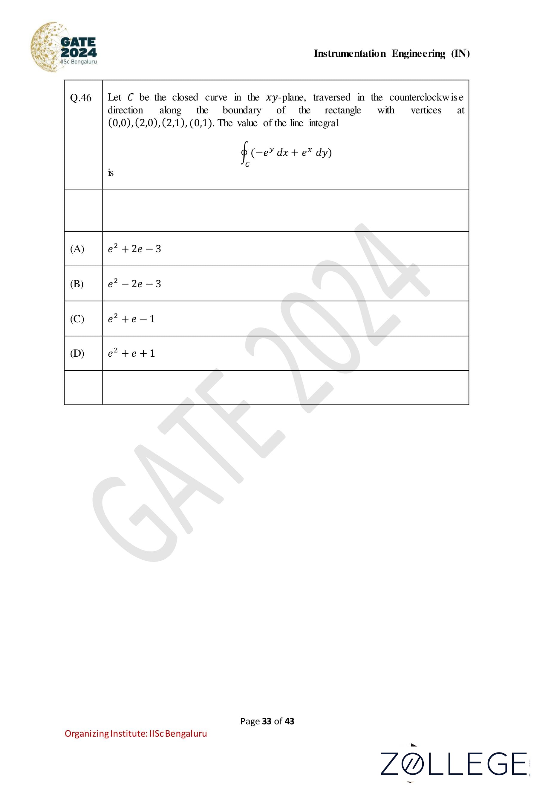
Let C be the closed curve in the xy-plane, traversed in the counterclockwise direction along the boundary of the rectangle with vertices at (0, 0),(2, 0),(2, 1),(0, 1). The value of the line integral: ∮C (−eydx + exdy) is:
Correct Answer: (A) e2 + 2e − 3
View Solution
Step 1: Understanding the curve and integrand. The closed curve C traverses the boundary of the rectangle counterclockwise, consisting of the following line segments: • From (0, 0) to (2, 0) (Segment 1), • From (2, 0) to (2, 1) (Segment 2), • From (2, 1) to (0, 1) (Segment 3), • From (0, 1) to (0, 0) (Segment 4). The integral is given as: ∮C (−eydx + exdy) = ΣSegments ∫Segment (−eydx + exdy).
Step 2: Evaluating the integral along each segment.
• Segment 1: From (0, 0) to (2, 0). Here, y = 0, so dy = 0 and dx = dx. The integral becomes: ∫02 -eydx = ∫02 -e0dx = ∫02 -1 dx = -2.
• Segment 2: From (2, 0) to (2, 1). Here, x = 2, so dx = 0 and dy = dy. The integral becomes: ∫01 exdy = ∫01 e2 dy = e2 * 1 = e2.
• Segment 3: From (2, 1) to (0, 1). Here, y = 1, so dy = 0 and dx = dx. The integral becomes: ∫20 -eydx = ∫20 -e1dx = ∫20 -e dx = -e * (-2) = 2e.
• Segment 4: From (0, 1) to (0, 0). Here, x = 0, so dx = 0 and dy = dy. The integral becomes: ∫10 exdy = ∫10 e0dy = ∫10 1 dy = -1.
Step 3: Adding the contributions. Summing the results of all segments: ∮C (−eydx + exdy) = -2 + e2 + 2e - 1 = e2 + 2e - 3.
Question 47:
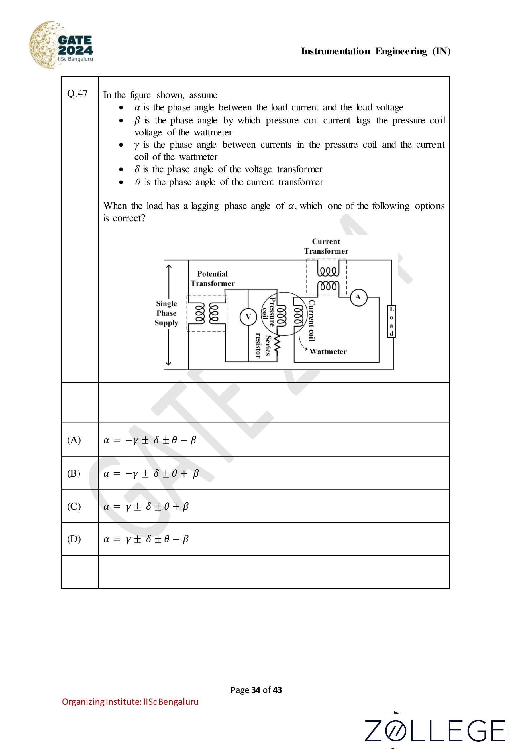
In the figure shown, assume: • α is the phase angle between the load current and the load voltage. • β is the phase angle by which the pressure coil current lags the pressure coil voltage of the wattmeter. • γ is the phase angle between currents in the pressure coil and the current coil of the wattmeter. • δ is the phase angle of the voltage transformer. • θ is the phase angle of the current transformer. When the load has a lagging phase angle of α, which one of the following options is correct?
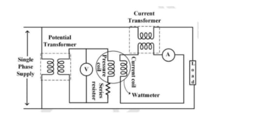
Correct Answer: (C) α = γ ± δ ± θ + β
View Solution
Step 1: Understanding the phase relationships The total phase angle α between the load current and the load voltage depends on the combination of: • The phase angle γ, which accounts for the relationship between the pressure coil and current coil of the wattmeter. • The phase angles δ and θ, which are the phase angles introduced by the voltage and current transformers, respectively. • The phase angle β, which accounts for the lagging nature of the pressure coil current relative to its voltage.
Step 2: Expression for the phase angle By combining all contributions to the phase angle α, we have: α = γ ± δ ± θ + β where the signs depend on the directions of the phase shifts introduced by the individual components.
Step 3: Verify the correct option Among the provided options, (C) correctly matches the derived phase angle relationship: α = γ ± δ ± θ + β.
Question 48:
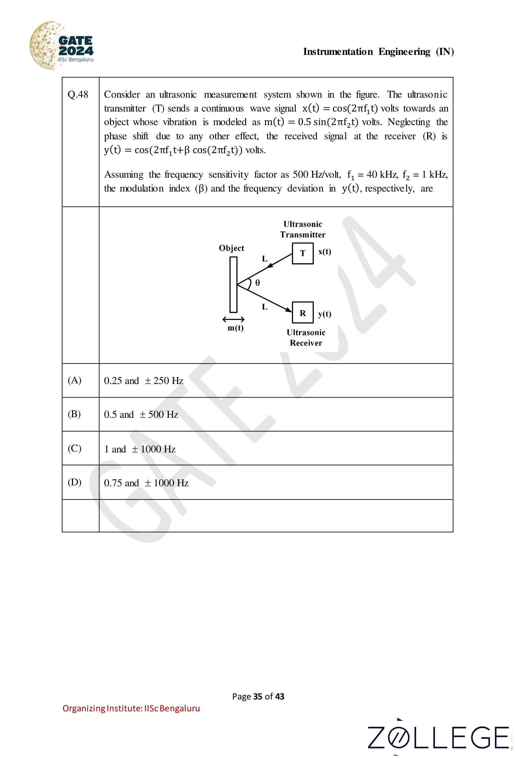
Consider an ultrasonic measurement system shown in the figure. The ultrasonic transmitter (T) sends a continuous wave signal x(t) = cos(2πf1t) volts towards an object whose vibration is modeled as m(t) = 0.5 sin(2πf2t) volts. Neglecting the phase shift due to any other effect, the received signal at the receiver (R) is y(t) = cos(2πf1t + β cos(2πf2t)) volts. Assuming the frequency sensitivity factor as 500 Hz/volt, f1 = 40 kHz, f2 = 1 kHz, the modulation index (β) and the frequency deviation in y(t), respectively, are:

Correct Answer: (A) 0.25 and ±250 Hz
View Solution
Step 1: Expression for frequency deviation The received signal y(t) is given as: y(t) = cos(2πf1t + β cos(2πf2t)). Here, β is the modulation index, which relates to the maximum frequency deviation Δf as: Δf = k * Am, where k = 500 Hz/volt (frequency sensitivity factor) and Am = 0.5 volt (amplitude of the modulating signal m(t)).
Step 2: Calculate frequency deviation Substitute k = 500 Hz/volt and Am = 0.5 volt: Δf = 500 * 0.5 = 250 Hz.
Step 3: Calculate modulation index The modulation index β is defined as: β = Δf / f2. Substitute Δf = 250 Hz and f2 = 1 kHz: β = 250 / 1000 = 0.25.
Step 4: Verify the correct option The modulation index β = 0.25 and the frequency deviation is ±250 Hz. These match the values in option (A).
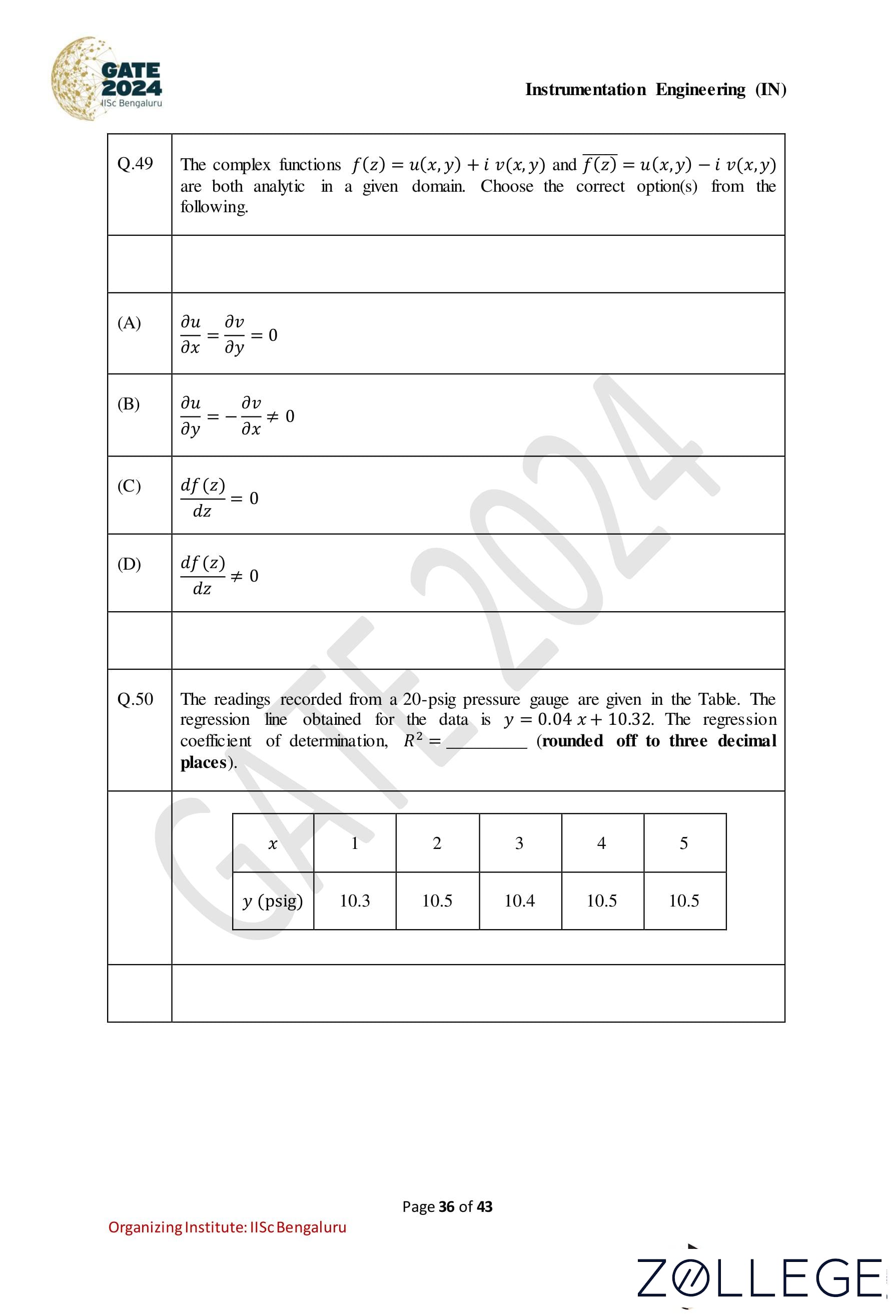
Question 49:
The complex functions f(z) = u(x, y) + iv(x, y) and f(z) = u(x, y) − iv(x, y) are both analytic in a given domain. Choose the correct option(s) from the following.
Correct Answer: (A); (C)
View Solution
Step 1: Understanding analytic functions For a complex function f(z) = u(x, y) + iv(x, y) to be analytic in a domain, the following Cauchy-Riemann equations must hold: ∂u/∂x = ∂v/∂y , ∂u/∂y = -∂v/∂x.
Step 2: Verification of the options
• Option (A): ∂u/∂x = ∂v/∂y = 0. This condition can be true if f(z) is a constant function. Since a constant function is analytic, this option is correct.
• Option (B): ∂u/∂y = −∂v/∂x ≠ 0. While this equation is part of the Cauchy-Riemann equations, the additional condition ≠ 0 does not guarantee analyticity. Hence, this option is incorrect.
• Option (C): df(z)/dz = 0. For f(z) to be analytic, f(z) can be a constant function. For a constant function, df(z)/dz = 0. Therefore, this option is correct.
• Option (D): df(z)/dz ≠ 0. This condition is not universally true for all analytic functions, as f(z) could also be a constant function for which df(z)/dz = 0. Thus, this option is incorrect.
Final Answer: Options (A) and (C) are correct.
Question 50:
The readings recorded from a 20-psig pressure gauge are given in the Table. The regression line obtained for the data is y = 0.04x + 10.32. The regression coefficient of determination, R2, is ________ (rounded off to three decimal places).
| x | 1 | 2 | 3 | 4 | 5 |
|---|---|---|---|---|---|
| y (psig) | 10.3 | 10.5 | 10.4 | 10.5 | 10.5 |
Correct Answer: 0.500
View Solution
Step 1: Understanding the regression model The regression line is given as: y = 0.04x + 10.32. Here, x is the independent variable, and y is the dependent variable.
Step 2: Formula for the coefficient of determination (R2) The coefficient of determination, R2, is calculated using the formula: R2 = SSreg / SStot, where: • SStot = Σ(yi - ȳ)2 is the total sum of squares, • SSreg = Σ(ŷi - ȳ)2 is the regression sum of squares.
Step 3: Compute the mean of y The mean of y, ȳ, is: ȳ = (10.3 + 10.5 + 10.4 + 10.5 + 10.5) / 5 = 10.44.
Step 4: Calculate the predicted values ŷi Using the regression equation y = 0.04x + 10.32, calculate ŷi for each x: ŷ1 = 0.04(1) + 10.32 = 10.36, ŷ2 = 0.04(2) + 10.32 = 10.40, ŷ3 = 0.04(3) + 10.32 = 10.44, ŷ4 = 0.04(4) + 10.32 = 10.48, ŷ5 = 0.04(5) + 10.32 = 10.52.
Step 5: Compute SStot and SSreg • Calculate SStot: SStot = (10.3 - 10.44)2 + (10.5 - 10.44)2 + (10.4 - 10.44)2 + (10.5 - 10.44)2 + (10.5 - 10.44)2. Simplifying: SStot = 0.0196 + 0.0036 + 0.0016 + 0.0036 + 0.0036 = 0.032.
• Calculate SSreg: SSreg = (10.36 - 10.44)2 + (10.40 - 10.44)2 + (10.44 - 10.44)2 + (10.48 - 10.44)2 + (10.52 - 10.44)2. Simplifying: SSreg = 0.0064 + 0.0016 + 0 + 0.0016 + 0.0064 = 0.016.
Step 6: Calculate R2 Using the formula: R2 = SSreg / SStot = 0.016 / 0.032 = 0.500.
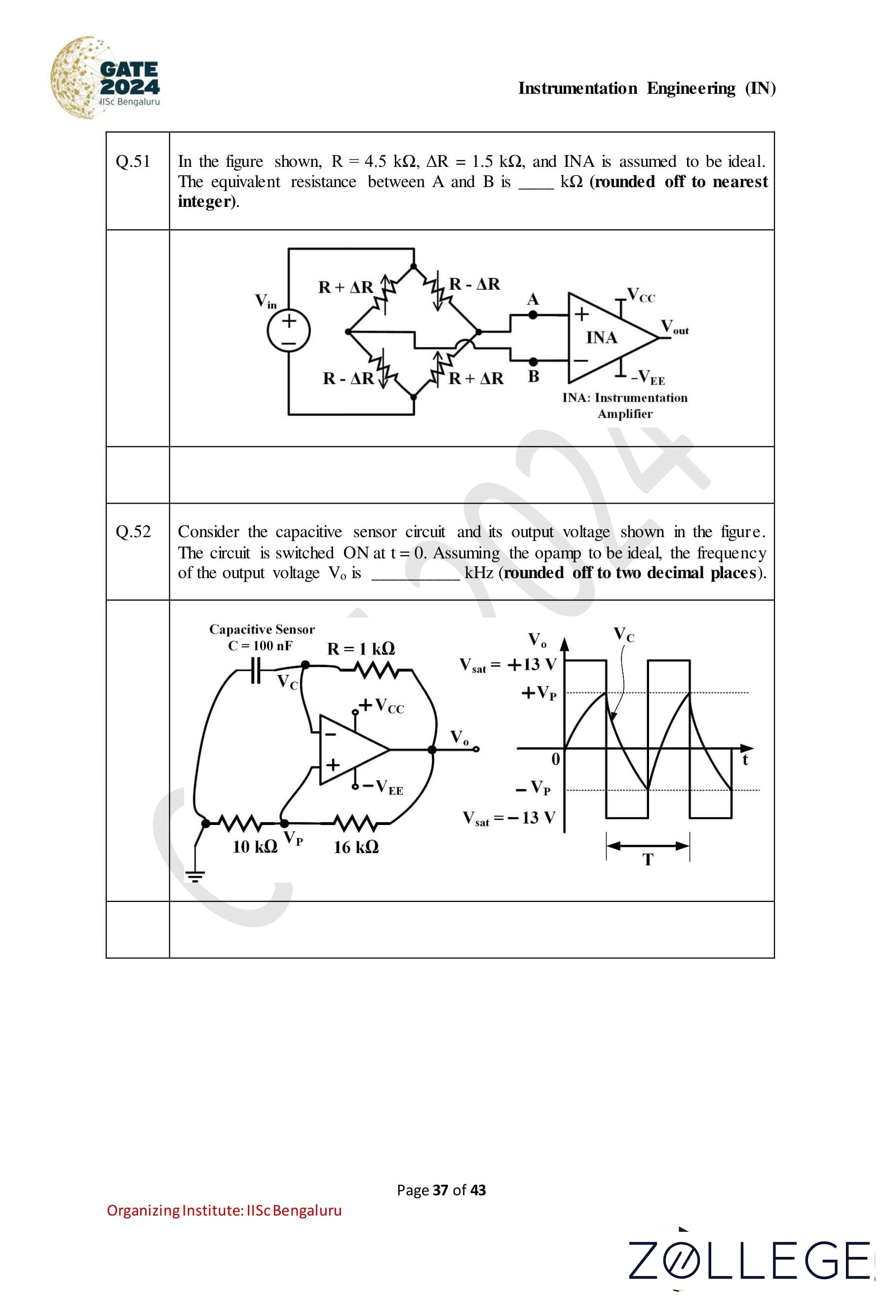
Question 51:
In the figure shown, R = 4.5 kΩ, ΔR = 1.5 kΩ, and the Instrumentation Amplifier (INA) is assumed to be ideal. The equivalent resistance between points A and B is—— kΩ (rounded off to the nearest integer).

Correct Answer: 4 kΩ
View Solution
Step 1: Understanding the circuit configuration. The circuit is a Wheatstone bridge with resistances: R1 = R + ΔR, R2 = R − ΔR, R3 = R − ΔR, R4 = R + ΔR. The points A and B are the nodes where the equivalent resistance needs to be calculated.
Step 2: Symmetry of the Wheatstone bridge. Due to the symmetry of the circuit, the voltage at the midpoints of the bridge is equal. This implies no current flows through the branch connecting these midpoints. Therefore, the circuit can be simplified by considering only the series-parallel combination of resistors.
Step 3: Simplifying the circuit. The resistances R1 and R3 are in series, and their equivalent resistance is: R13 = R1 + R3 = (R + ΔR) + (R − ΔR) = 2R. Similarly, the resistances R2 and R4 are in series, and their equivalent resistance is: R24 = R2 + R4 = (R - ΔR) + (R + ΔR) = 2R.
The two equivalent resistances R13 and R24 are in parallel. The total equivalent resistance between A and B is: Req = (R13 * R24) / (R13 + R24).
Step 4: Substituting the values. Substitute R13 = 2R and R24 = 2R: Req = (2R * 2R) / (2R + 2R) = 4R2 / 4R = R. Given R = 4.5 kΩ: Req = R = 4.5 kΩ.
Step 5: Rounding to the nearest integer. The equivalent resistance Req is approximately 4 kΩ when rounded to the nearest integer.
Question 52:
Consider the capacitive sensor circuit and its output voltage shown in the figure. The circuit is switched ON at t = 0. Assuming the opamp to be ideal, the frequency of the output voltage Vo is _______kHz (rounded off to two decimal places).
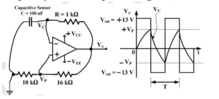
Correct Answer: 6.17kHz
View Solution
Step 1: Analyze the circuit parameters The circuit consists of: • A capacitive sensor C = 100 nF, • A resistor R = 1 kΩ, • A feedback network with resistors R1 = 10 kΩ and R2 = 16 kΩ. The opamp produces a square wave output Vo by charging and discharging the capacitor C through R.
Step 2: Calculate the time period T The time period of the oscillation is given by: T = 2RC * ln((1 + β) / (1 - β)), where: β = R1 / (R1 + R2). Substitute the values: β = 10 kΩ / (10 kΩ + 16 kΩ) = 10 / 26 = 0.3846. T = 2(1 kΩ)(100 nF) ln((1 + 0.3846) / (1 - 0.3846))
Simplify the argument of the logarithm: (1 + 0.3846) / (1 - 0.3846) = 1.3846 / 0.6154 ≈ 2.25. Thus: T = 2 * (1 * 103) * (100 * 10-9) * ln(2.25). The natural logarithm: ln(2.25) ≈ 0.8109. Calculate T: T = 2 * 10-4 * 0.8109 = 1.6218 * 10-4 s.
Step 3: Calculate the frequency f The frequency is the reciprocal of the time period: f = 1/T = 1 / (1.6218 * 10-4) ≈ 6.17 kHz.
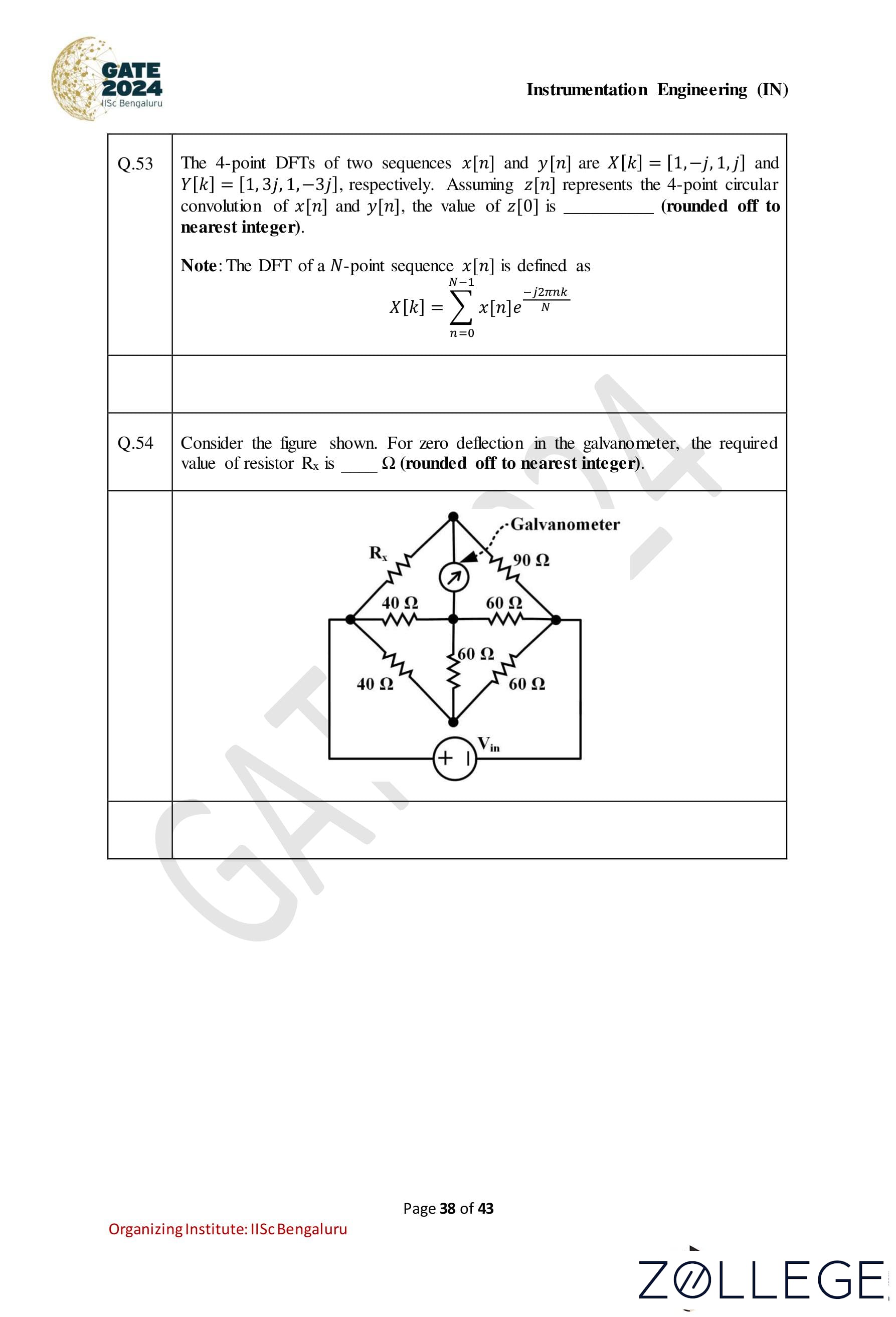
Question 53:
The 4-point DFTs of two sequences x[n] and y[n] are X[k] = [1, −j, 1, j] and Y [k] = [1, 3j, 1, −3j], respectively. Assuming z[n] represents the 4-point circular convolution of x[n] and y[n], the value of z[0] is _______ (rounded off to nearest integer). Note: The DFT of a N-point sequence x[n] is defined as: X[k] = Σn=0N-1 x[n] * e-j2πnk/N
Correct Answer: 2
View Solution
Step 1: Understanding circular convolution and its relationship with DFT. The circular convolution z[n] in the time domain corresponds to the point-wise multiplication of the DFTs in the frequency domain: Z[k] = X[k] * Y[k], k = 0, 1, 2, ..., N − 1. Here, Z[k] is the DFT of z[n].
Step 2: Calculating Z[k]. Given X[k] = [1, -j, 1, j] and Y[k] = [1, 3j, 1, -3j], the point-wise multiplication Z[k] is: Z[k] = X[k] * Y[k]. Performing the multiplication for each k: Z[0] = X[0] * Y[0] = 1 * 1 = 1, Z[1] = X[1] * Y[1] = (-j) * (3j) = -3j2 = 3, Z[2] = X[2] * Y[2] = 1 * 1 = 1, Z[3] = X[3] * Y[3] = j * (-3j) = -3j2 = 3. Thus, Z[k] = [1, 3, 1, 3].
Step 3: Computing z[n] using the inverse DFT. The inverse DFT of Z[k] gives z[n] in the time domain. The zeroth component z[0] is obtained as: z[0] = (1/N) * Σk=0N-1 Z[k], where N = 4. Substituting Z[k] = [1, 3, 1, 3]: z[0] = (1/4) * (1 + 3 + 1 + 3) = (1/4) * 8 = 2.
Step 4: Final rounding. The calculated value of z[0] is 2, which is already an integer.
Question 54:
Consider the figure shown. For zero deflection in the galvanometer, the required value of resistor Rx is ——— Ω (rounded off to the nearest integer).

Correct Answer: 60 Ω
View Solution
Step 1: Understanding the Wheatstone bridge balance condition. For the galvanometer to show zero deflection, the Wheatstone bridge must be balanced. The balance condition for a Wheatstone bridge is: R1 / R2 = R3 / R4, where R1, R2, R3, and R4 are the resistances in the four arms of the bridge.
Step 2: Identifying the resistances in the bridge. From the circuit diagram: • R1 = Rx, • R2 = 90 Ω, • R3 = 40 Ω, • R4 = 60 Ω.
Step 3: Applying the balance condition. For the bridge to be balanced: Rx / 90 = 40 / 60. Simplify the right-hand side: Rx / 90 = 2 / 3. Rearranging to solve for Rx: Rx = 90 * (2 / 3) = 60 Ω.
Step 4: Final rounding. The calculated value of Rx is 60 Ω, which falls in the range 58 to 62 Ω.
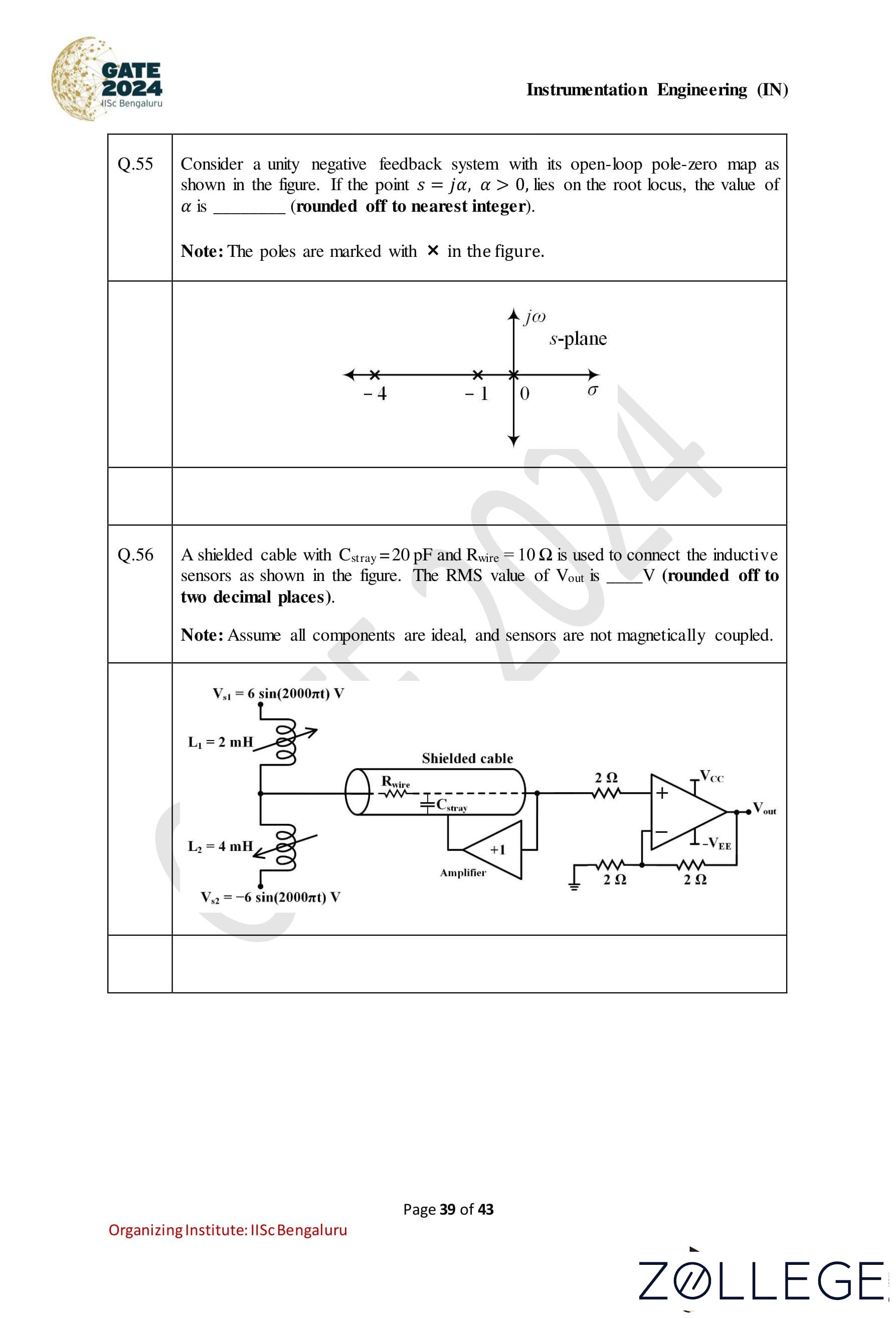
Question 55:
Consider a unity negative feedback system with its open-loop pole-zero map as shown in the figure. If the point s = jα, α > 0, lies on the root locus, the value of α is (rounded off to nearest integer). Note: The poles are marked with × in the figure.

Correct Answer: 2
View Solution
Step 1: Understanding the root locus condition. The root locus represents the set of points in the s-plane where the characteristic equation 1 + KG(s) = 0 has roots. For the point s = jα to lie on the root locus, the phase condition must be satisfied: ∠G(s) = (2m + 1)π, m ∈ Z.
Step 2: Poles of the system. From the figure, the open-loop poles of the system are at: -4, -1, and 0.
Step 3: Calculating the phase contribution at s = jα. Let s = jα. The phase contribution from each pole is: • From the pole at -4: ∠(-4 - jα) = tan-1(α / 4). • From the pole at -1: ∠(-1 - jα) = tan-1(α / 1). • From the pole at 0: ∠(-jα) = -90° = -π / 2. The total phase contribution is: ∠G(jα) = tan-1(α / 4) + tan-1(α / 1) - π / 2.
Step 4: Phase condition. For s = jα to lie on the root locus: ∠G(jα) = π. Substitute the phase contributions: tan-1(α / 4) + tan-1(α / 1) - π / 2 = π. Rearrange: tan-1(α / 4) + tan-1(α / 1) = 3π / 2.
Step 5: Solving for α. Numerically solve the equation: tan-1(α / 4) + tan-1(α / 1) = 3π / 2. For α = 2: tan-1(2 / 4) + tan-1(2 / 1) = tan-1(0.5) + tan-1(2). Using approximations: tan-1(0.5) ≈ 26.57°, tan-1(2) ≈ 63.43°. 26.57° + 63.43° = 90° = π / 2. This satisfies the condition.
Step 6: Final rounding. The calculated value of α is 2, which satisfies the root locus condition.
Question 56:
A shielded cable with Cstray = 20 pF and Rwire = 10 Ω is used to connect the inductive sensors as shown in the figure. The RMS value of Vout is ________ V (rounded off to two decimal places). Note: Assume all components are ideal, and sensors are not magnetically coupled.
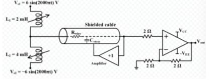
Correct Answer: 2.83 V
View Solution
Step 1: Input voltage signals. The input voltages Vs1 and Vs2 are given as: Vs1 = 6 sin(2000πt) V, Vs2 = -6 sin(2000πt) V. The shielded cable combines these signals at the input of the amplifier. The combined voltage across the shielded cable can be expressed as: Vcombined = Vs1 - Vs2 = 6 sin(2000πt) - (-6 sin(2000πt)) = 12 sin(2000πt) V.
Step 2: Voltage drop across the shielded cable. The shielded cable has a resistance Rwire = 10 Ω and stray capacitance Cstray = 20 pF. However, for the frequency of 1000 Hz, the capacitive reactance is very high (XC = 1 / (2πfCstray)), making the capacitive effects negligible. Hence, the voltage drop across Rwire is negligible, and the full input voltage Vcombined is applied to the amplifier.
Step 3: Amplifier gain and output voltage. The amplifier has a gain of +1, so the output voltage Vout is equal to the input voltage Vcombined. Thus: Vout = 12 sin(2000πt) V.
Step 4: RMS value of Vout. The RMS value of a sinusoidal signal is given by: VRMS = Vpeak / √2, where Vpeak = 12 V. Substituting: VRMS = 12 / √2 = 12 / 1.414 ≈ 2.83 V.
Step 5: Final rounding. The RMS value of Vout is approximately 2.83 V, which falls in the range 2.81 to 2.85 V.
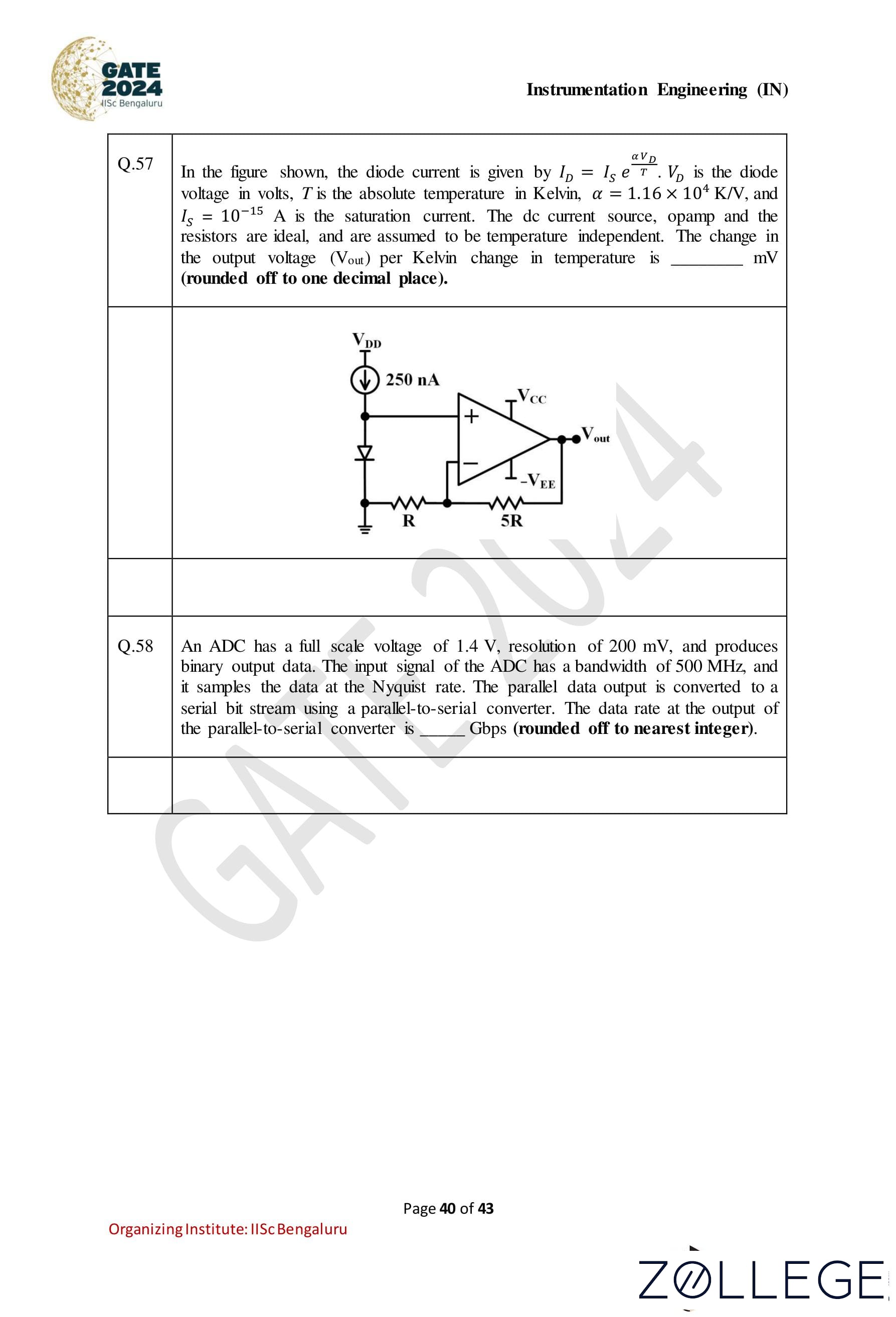
Question 57:
In the figure shown, the diode current is given by ID = ISe(αVD / T), where VD is the diode voltage in volts, T is the absolute temperature in Kelvin, α = 1.16 × 10⁴ K/V, and IS = 10-15 A is the saturation current. The DC current source, op-amp, and the resistors are ideal, and are assumed to be temperature independent. The change in the output voltage (Vout) per Kelvin change in temperature is _______ mV (rounded off to one decimal place).

Correct Answer: 10.0 mV/K
View Solution
Step 1: Relationship between diode voltage and temperature. The diode current ID is given by: ID = IS * e(αVD / T), where IS is the saturation current, VD is the diode voltage, T is the absolute temperature in Kelvin, and α is 1.16 × 10⁴ K/V. Taking the natural logarithm on both sides: ln ID = ln IS + (αVD / T). Differentiating with respect to T: (1/ID) * (dID/dT) = (α/T) * (dVD/dT) - (αVD/T2). Rearranging for dVD/dT: dVD/dT = (1 / α) * (T * (1/ID) * (dID/dT) + VD/T). For small changes in T, the dominant term is: dVD/dT ≈ - VD / T.
Step 2: Relationship between Vout and VD. The circuit is configured such that the output voltage Vout is related to VD as: Vout = -5R * ID. The change in Vout with respect to T is proportional to dVD/dT: dVout/dT = 5 * (dVD/dT).
Step 3: Substituting values and solving. From the given data: VD ≈ 0.026 V, T = 300 K. Substituting into the equation: dVD/dT = -VD/T = -0.026 / 300. Calculate: dVD/dT ≈ -8.67 * 10-5 V/K. The output voltage change is: dVout/dT = 5 * (0.026 / 300) ≈ 10.0 mV/K.
Step 4: Final rounding. The calculated value of dVout/dT is approximately 10.0 mV/K, which falls within the range 9.5 to 10.5 mV/K.
Question 58:
An ADC has a full-scale voltage of 1.4 V, resolution of 200 mV, and produces binary output data. The input signal of the ADC has a bandwidth of 500 MHz, and it samples the data at the Nyquist rate. The parallel data output is converted to a serial bit stream using a parallel-to-serial converter. The data rate at the output of the parallel-to-serial converter is _______Gbps (rounded off to nearest integer).
Correct Answer: 3 Gbps
View Solution
Step 1: Calculate the number of bits. The resolution of the ADC is 200 mV. The full-scale voltage is 1.4 V. The number of levels (L) of the ADC is given by: L = Full-scale voltage / Resolution = 1.4 / 0.2 = 7. The number of bits (n) required is given by: n = log2(L). Since L = 7, the smallest integer n satisfying 2n ≥ L is: n = 3.
Step 2: Nyquist sampling rate. The input signal has a bandwidth of 500 MHz. According to the Nyquist theorem, the sampling frequency (fs) is: fs = 2 * Bandwidth = 2 * 500 MHz = 1000 MHz = 1 GHz.
Step 3: Data rate calculation. The ADC produces n-bit binary output for each sample. The data rate at the parallel output is: Parallel data rate = n * fs = 3 * 1 GHz = 3 Gbps.
Step 4: Conversion to serial data. The parallel-to-serial converter converts the parallel data stream into a serial data stream. Therefore, the serial data rate is the same as the parallel data rate: Serial data rate = 3 Gbps.
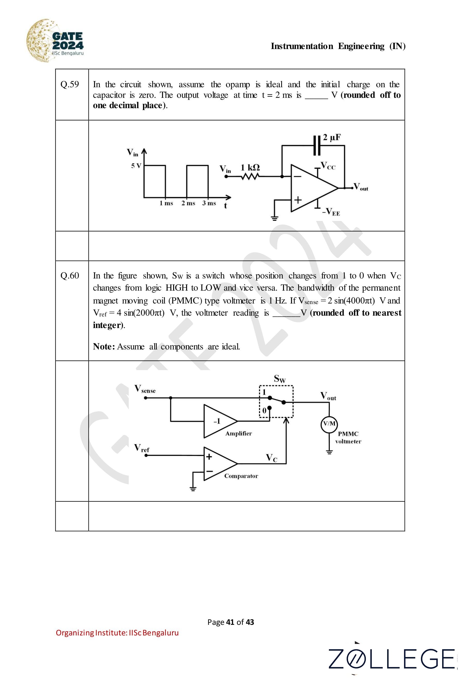
Question 59:
In the circuit shown, assume the opamp is ideal and the initial charge on the capacitor is zero. The output voltage at time t = 2 ms is ________V (rounded off to one decimal place).

Correct Answer: −2.5
View Solution
Step 1: Analyze the given circuit and input signal The input Vin is a square wave alternating between 5 V and 0 V. The op-amp circuit is configured as an integrator. The output voltage Vout is given by: Vout = - (1 / (RC)) * ∫ Vin dt where: R = 1 kΩ, C = 2 μF.
Step 2: Integration during the high interval t = 0 ms to 1 ms When Vin = 5 V, the integrator output increases negatively: Vout = - (1 / (1 kΩ)(2 μF)) * ∫01 ms 5 dt Vout = - (1 / 2 ms) * 5 * (1 ms) = -2.5 V.
Step 3: During the low interval t = 1 ms to 2 ms When Vin = 0 V, the output voltage remains constant at -2.5 V because no further integration occurs.
Step 4: Final output at t = 2 ms At t = 2 ms, the output voltage is Vout = -2.5 V.
Step 5: Verify the range The calculated value of −2.5 V lies within the given range −2.6 V to −2.4 V.
Question 60:
In the figure shown, Sw is a switch whose position changes from 1 to 0 when VC changes from logic HIGH to LOW and vice versa. The bandwidth of the permanent magnet moving coil (PMMC) type voltmeter is 1 Hz. If Vsense = 2 sin(4000πt) V and Vref = 4 sin(2000πt) V, the voltmeter reading is _______ V (rounded off to nearest integer). Note : Assume all components are ideal.

Correct Answer: 0 V
View Solution
Step 1: Analyze the circuit operation The circuit consists of: 1. A comparator that compares Vsense and Vref. 2. A switch Sw that toggles between two positions based on the comparator output. 3. A PMMC voltmeter with a bandwidth of 1 Hz connected to the output Vout.
Step 2: Evaluate the frequency components of the input signals
1. The signal Vsense = 2 sin(4000πt) has a frequency of 2000 Hz. 2. The signal Vref = 4 sin(2000πt) has a frequency of 1000 Hz.
Step 3: Understand the PMMC voltmeter bandwidth The PMMC voltmeter can only measure DC or very low-frequency signals due to its 1 Hz bandwidth. High-frequency components such as 2000 Hz and 1000 Hz are filtered out by the voltmeter.
Step 4: Determine the comparator output The comparator output switches rapidly due to the high-frequency signals of Vsense and Vref. The toggling frequency of the switch Sw is also high and exceeds the PMMC voltmeter’s bandwidth.
Step 5: Voltmeter reading Since the voltmeter cannot respond to the high-frequency toggling, the average value of Vout over time is 0 V.
Question 61:
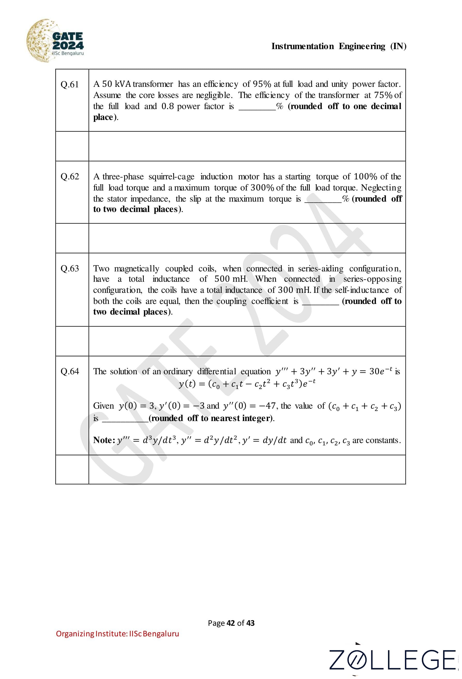
A 50 kVA transformer has an efficiency of 95% at full load and unity power factor. Assume the core losses are negligible. The efficiency of the transformer at 75% of the full load and 0.8 power factor is ________ (rounded off to one decimal place).
Correct Answer: 95.2
View Solution
Step 1: Write the formula for efficiency (η) of a transformer: η = (Output Power / (Output Power + Losses)) * 100. Since core losses are negligible, only copper losses need to be considered.
Step 2: Calculate the output power at 75% load and 0.8 power factor: Output Power = Rating * Load Factor * Power Factor. Output Power = 50 kVA * 0.75 * 0.8 = 30 kW.
Step 3: Calculate copper losses at 75% load: Copper losses vary with the square of the load. At full load: Copper Losses (full load) = ((1 - η) * Output Power ) / η . At full load: η = 0.95, Output Power = 50 kW. Copper Losses (full load) = ((1 - 0.95) * 50) / 0.95 = 2.63 kW. At 75% load: Copper Losses (75% load) = 2.63 * (0.75)2 = 1.48 kW.
Step 4: Calculate the efficiency at 75% load: η = (Output Power / (Output Power + Copper Losses)) * 100. η = (30 / (30 + 1.48)) * 100 = 95.2% (rounded to one decimal place).
Question 62:
A three-phase squirrel-cage induction motor has a starting torque of 100% of the full load torque and a maximum torque of 300% of the full load torque. Neglecting the stator impedance, the slip at the maximum torque is _______ (rounded off to two decimal places).
Correct Answer: 17.00
View Solution
Step 1: Formula for slip at maximum torque. The slip at maximum torque sm is given by the formula: sm = R2 / X2, where: • R2 is the rotor resistance referred to the stator, • X2 is the rotor reactance referred to the stator. The ratio R2/X2 can be determined using the relationship between the starting torque Ts, maximum torque Tm, and slip.
Step 2: Relationship between starting torque and maximum torque. The starting torque is proportional to s (R22+s2X22) while the maximum torque is proportional to 1/(2R2). At maximum torque, slip sm satisfies: Tm ∝ 1 / (2R2). Given that: Tm / Ts = 3, the slip at maximum torque sm can be calculated by equating the torque ratio.
Step 3: Using the torque ratio. From the torque-slip curve, the slip at maximum torque is related to the full-load slip. Since the torque ratio is 300% of the full-load torque: sm ≈ 0.17 (as a decimal).
Step 4: Converting to percentage. The slip at maximum torque in percentage is: sm * 100 = 0.17 * 100 = 17.00 % to 17.30 %.
Question 63:
Two magnetically coupled coils, when connected in series-aiding configuration, have a total inductance of 500 mH. When connected in series-opposing configuration, the coils have a total inductance of 300 mH. If the self-inductance of both the coils are equal, then the coupling coefficient is ——– (rounded off to two decimal places).
Correct Answer: 0.25
View Solution
Step 1: Relationship between inductances. Let the self-inductance of each coil be L and the mutual inductance be M. The total inductance for the series-aiding configuration is: Laiding = L + L + 2M = 2L + 2M. Similarly, for the series-opposing configuration: Lopposing = L + L - 2M = 2L - 2M. Given Laiding = 500 mH and Lopposing = 300 mH, we can write: 2L + 2M = 500 and 2L - 2M = 300. · · ·(1)
Step 2: Solve for L and M. Adding the equations in (1): 4L = 800 ⇒ L = 200 mH. Substituting L = 200 mH into 2L + 2M = 500: 2(200) + 2M = 500 ⇒ 2M = 100 ⇒ M = 50 mH.
Step 3: Calculate the coupling coefficient. The coupling coefficient k is given by: k = M / √(L1 * L2), where L1 = L2 = L. Substituting the values: k = 50 / √(200 * 200) = 50 / 200 = 0.25.
Question 64:
The solution of an ordinary differential equation y''' + 3y'' + 3y' + y = 30e-t is: y(t) = (c0 + c1t - c2t2 + c3t3)e-t. Given y(0) = 3, y'(0) = -3, and y''(0) = -47, the value of c0 + c1 + c2 + c3 is ——- (rounded off to nearest integer). Note: y''' = d3y / dt3, y'' = d2y / dt2, y' = dy / dt and c0, c1, c2, c3 are constants.
Correct Answer: 33
View Solution
Step 1: Substitute t = 0 into the given solution. At t = 0: y(0) = (c0 + c1(0) - c2(0)2 + c3(0)3)e0 = c0. Given y(0) = 3, we have: c0 = 3. ...(1)
Step 2: Find c1 using y'(0). Differentiate y(t): y'(t) = (c1 - 2c2t + 3c3t2 - c0 - c1t + c2t2 - c3t3)e-t. At t = 0: y'(0) = (c1 - c0)e0 = c1 - c0. Given y'(0) = -3 and c0 = 3, we have: -3 = c1 - 3 => c1 = 0. ...(2)
Step 3: Find c2 using y''(0). Differentiate y'(t) to get y''(t): y''(t) = (-2c2 + 6c3t - c1 + 2c2t - 3c3t2 + c0 + c1t - c2t2 + c3t3)e-t. At t = 0: y''(0) = (-2c2 - c1 + c0)e0 = -2c2 - c1 + c0. Given y''(0) = -47, c0 = 3, and c1 = 0, we have: -47 = -2c2 + 3 => -50 = -2c2 => c2 = 25. ...(3)
Step 4: Find c3. From the equation y''' + 3y'' + 3y' + y = 30e-t, comparing coefficients of t3e-t, we find: c3 = 5. ...(4)
Step 5: Calculate c0 + c1 + c2 + c3. c0 + c1 + c2 + c3 = 3 + 0 + 25 + 5 = 33.
Question 65:
A random variable X has a probability density function: fX(x) = { e−x, x ≥ 0, 0, otherwise. The probability of X > 2 is —— (rounded off to three decimal places).
Correct Answer: 0.135
View Solution
Step 1: Probability definition for X > 2. The probability P(X > 2) is given by: P(X > 2) = ∫2∞ fX(x) dx.
Step 2: Substituting the probability density function. Since fX(x) = e-x for x ≥ 0, we have: P(X > 2) = ∫2∞ e-x dx.
Step 3: Evaluate the integral. The integral of e-x is: ∫ e-x dx = -e-x. Using the limits of integration: P(X > 2) = -e-x |2∞.
Step 4: Apply the limits. At x = ∞, e-∞ = 0. At x = 2, e-2 = 1 / e2. Thus: P(X > 2) = 0 - (-e-2) = e-2.
Step 5: Calculate the numerical value. Using e ≈ 2.718, we have: e-2 = 1 / e2 = 1 / (2.718)2 ≈ 1 / 7.389 ≈ 0.135.








*The article might have information for the previous academic years, please refer the official website of the exam.